SlideShare a Scribd company logo
1 of 10
Download to read offline
Fixed or Semi-Fixed
Fire Protection Systems for
Storage Tanks
In the early years of the oil industry, fire in a storage
tank was a common occurrence. Virtually all
products were stored in cone roof tanks built of
riveted steel plates and the roof was often
constructed with wood and tar coated paper. Tank
fires were common especially after a lightning
storm. This costly experience gradually led to
improvements in better codes and guidelines for
handling storage tank fires. Floating roof tanks
were adopted for low flash point petroleum products
and proved to be a most reliable method of
protection against losses due to fires. The less
volatile products with higher flash points continue to
be stored in welded steel cone roof tanks.
As the frequency of fully involved storage tank fires
decreases to a more acceptable level, the size of
fire, when it happens, becomes larger due to the
increase in tank size and capacity. It is quite
common to see tanks with diameters in excess of
328 ft. (100 meters) capable of storing a million
barrels of product.
One practical method to protect flammable liquid
storage tanks from fire is with a fixed or a semi-
fixed foam fire protection system. When
engineered, installed and maintained correctly,
these systems will give many years of reliable
service. The foam system can be used for fire
prevention, control or direct extinguishment of any
flammable or combustible liquid fire within the tank.
To select the correct foam system, it is necessary
to understand the following systems:
Fixed System is a complete installation piped from
a central foam station, discharging through fixed
discharge devices on the hazard being protected?
Foam proportioning components are permanently
installed.
Semi Fixed System is an installation where the
hazard is equipped with fixed discharge device(s),
which connect to piping that terminates a safe
distance from the hazard, normally outside the dike
wall. Foam producing materials are transported to
the scene after the fire starts and are connected to
the piping.
Listed below are types of tanks commonly used for
the storage of combustible or flammable liquids.
• Cone roof tank
• Open top floating roof tank
• Internal floating roof tank/covered floating roof
Cone Roof Storage Tank has vertical sides and is
equipped with a fixed cone-shaped roof that is
welded to the sides of the tank. Tanks that have
been designed in accordance with API standards
have a weak seam at the joint where the roof and
sides meet. In the event of an internal explosion,
the roof separates and blows off leaving the tank
shell intact. This system allows the tank to retain its
contents and any resulting fire will involve the full
surface of the exposed flammable liquid.
Open Top Floating Roof Storage Tank is similar
to the cone roof tank in construction but with the
exception that it has no fixed roof. A pontoon type
roof floats directly on the flammable liquid surface.
This floating roof has a mechanical shoe or tube
seal attached to its full perimeter. The rim seal
covers the space between the floating roof and the
tank shell (side wall).
Internal Floating Roof/Covered Floating Roof
Storage Tank is a combination of both the cone
roof and the open top-floating roof tank? The tank
has a cone roof but with the addition of an internal
floating roof or pan that floats directly on the fuel
surface. The open vents in the tank sidewalls just
beneath the roof joint can identify this type of tank.
If the internal floating roof is other than a steel
double deck or pontoon type, the fire protection
system should be designed for full surface fires
(similar to cone roof tanks). For the double deck or
pontoon internal roofs of steel construction, a
design for sealed area protection may be permitted
(same as open floating roof tanks).
Small quantities of flammable liquids are sometimes
stored in horizontal style tanks, which normally sit
on saddles or in underground storage facilities. This
section applies only to the three major types of
tanks as listed above.
CHEMGUARD
204 S. 6th
Ave • Mansfield, Tx 76063 • (817) 473-9964 • FAX (817) 473-0606
www.chemguard.com
DATA SHEET #D10D03190
REVISON: 09/2005
CHEMGUARD
204 S. 6th
Ave • Mansfield, Tx 76063 • (817) 473-9964 • FAX (817) 473-0606
www.chemguard.com
IDENTIFY THE FLAMMABLE LIQUID
There are two basic classifications of flammable
and combustible liquids:
• Hydrocarbon (non water miscible)
• Polar Solvent (water miscible)
Hydrocarbons include non water-soluble petroleum
liquids such as crude oil, gasoline, jet fuels, fuel
oils, etc. Polar solvents include water soluble
liquids such as alcohols, ketones, esters etc.
All Chemguard U.L. Listed and standard grade
foam concentrates are suitable for use on
hydrocarbon fuel fires or spills. Only Chemguard
U.L. Listed and standard grade alcohol resistant
AR-AFFF concentrates are suitable for use on polar
solvent fuel fires or spills.
NOTE: Pure MTBE is only slightly water miscible
(approx. 4% - 6%).
FLAMMABLE AND COMBUSTIBLE LIQUIDS
PER NFPA 30
Flammable Liquid means liquid having a flash
point below 100ºF (37.8ºC) and having a vapor
pressure not exceeding 40 psi (276 kpa)(absolute)
at 100ºF (37.8ºC) shall be known as a Class I liquid.
Class I liquids shall be subdivided as follows:
• Class IA includes those having flash points
below 73ºF (22.8ºC) and having a boiling point
below 100ºF (37.8ºC).
• Class IB includes those having flash points
below 73ºF (22.8ºC) and having a boiling point
above 100ºF (37.8ºC).
• Class IC includes those having flash points at or
above 73ºF (22.8ºC) and below 100ºF (37.8ºC).
Combustible Liquid means liquid having a flash
point at or above 100ºF (37.8ºC). Combustible
liquids shall be subdivided as follows:
• Class II includes liquids with having flash points
at or above 100ºF (37.8ºC) and below 140ºF
(60ºC).
• Class IIIA includes liquids with a flash points at
or above 140ºF (60ºC) and below 200ºF (93.3ºC).
• Class IIIB includes liquids with having flash
points at or above 200ºF (93.3ºC).
FIRE PROTECTION OF STORAGE TANKS
U.L. has established two different types of foam
discharge outlets:
Type II Discharge Outlet - A fixed device that
delivers foam onto the burning liquid and partially
submerges the foam and produces restricted
agitation of the surface. Examples of this type of
device are Foam Chambers and Foam Makers.
Type III Discharge Outlet - A fixed or portable
device that delivers foam in a manner that causes
the foam to fall directly onto the surface of the
burning liquid in such a way that causes general
agitation. Examples of this type of device are Hose
Stream Nozzles and Monitors.
Two basic methods of fire protection systems for
storage tanks:
• Sub-surface Base Injection
• Over the Top - (Subdivided as follows) Foam
Chambers, Foam Makers, Portable Foam
Monitors and Foam Tower
SUB-SURFACE BASE INJECTION
The sub-surface method of fire protection produces
foam with a HBPFM located outside the storage
tank. This system delivers the expanded foam
mass through piping into the base of the tank. The
pipe may be an existing product line or can be a
dedicated fire protection foam line. The expanded
foam entering the tank through a discharge outlet is
injected into the flammable liquid. The discharge
outlet must be a minimum of 1 ft. above any water
that may be present at the base of the tank. The
foam will be destroyed if injected into the water
layer. When injected into the fuel, the foam will rise
through the fuel and form a vapor tight foam blanket
on the fuel surface.
Advantages of Sub-Surface
• The rising foam can cause the fuel in the tank to
circulate which can assist in cooling the fuel at
the surface.
• If there is an explosion and fire that could
damage the top of the tank, the sub-surface
injection system is not likely to suffer damage
• The discharging foam is more efficiently
directed to the fuel surface without any
interruption from the thermal updraft of the fire.
DATA SHEET #D10D03190
REVISON: 09/2005
CHEMGUARD
204 S. 6th
Ave • Mansfield, Tx 76063 • (817) 473-9964 • FAX (817) 473-0606
www.chemguard.com
Disadvantages of Sub-Surface
• CANNOT be used in storage tanks containing
polar solvent type fuels or products that require
the use of AR-AFFF type foam concentrates
• Not recommended for use in either Floating
Roof or Internal Floating Roof type tanks.
• Caution must be used so that the maximum
foam inlet velocity is not exceeded; otherwise,
excessive fuel pickup by the foam as it enters
the tank will be experienced.
• Not to be used for protection of Class 1A
hydrocarbon liquids
HIGH BACK PRESSURE FOAM MAKER
The HBPFM device is mounted in the foam line
used to aspirate the foam solution before it is
discharged into the storage tank base. It will
typically give an expansion ratio of between 2:1 and
4:1. The device is capable of discharging against
considerable backpressure, which can be as high
as 40% of the operating pressure. The
backpressure is an accumulation of head pressure
in the fuel inside the storage tank and any friction
loss between the foam maker and the tank. A
minimum of 100-psi inlet pressure into the HBPFM
is normally required to ensure correct operation.
The foam velocity through the piping to the tank
from the HBPFM is very critical. With flammable
liquids, the foam velocity entering the tank should
NOT exceed 10 ft. per second and with combustible
liquids the foam velocity should NOT exceed 20 ft.
per second.
Following chart shows the minimum discharge times and
application rates for sub-surface application:
Hydrocarbon Type Fuel Minimum Minimum
Discharge Application
Time Rate
Flash point between 100ºF 30 min. 0.10 gpm / ft.
and 140ºF (37.8ºC and 93.3ºC) 4.1 L/min./m
Flash point below 100ºF 55 min. 0.10 gpm / ft.
(37.8ºC) liquids heated above 4.1 L/min./m
their flash points.
Crude Petroleum 55 min. 0.10 gpm / ft.
4.1 L/min./m
NOTE: The maximum application rate shall be 0.20
gpm / ft. (8.1 L/min./m).
FOAM CHAMBERS (TYPE II DISCHARGE DEVICE)
The Foam Chamber is normally used on cone roof
storage tanks. The chamber is bolted or welded on
the outside of the tank shell near the roof joint. A
deflector is mounted on the inside of the tank so
that the discharging foam from the foam chamber
will be diverted back against the inside of the tank
wall.
The foam chamber is mounted on the cone roof
storage tank wall shell in a vertical position just
below the roof joint, or approximately 8" to 12"
down from the roof joint to the center point of the
foam chamber outlet. In sequence Chemguard
Models FC 2.5, 3, 4 and 6 foam chambers are to be
mounted from approx. 8" to approx. 12” down from
the roof joint. When the foam chamber is mounted
correctly, the internal glass seal of the chamber will
be just slightly higher in elevation than the roof joint
on the storage tank. Each foam chamber mounted
on a cone roof storage tank SHOULD have its own
individually valved riser supplying the foam solution
from outside the dike area. For correct operation, a
minimum of 40 psi is required at the inlet to the
foam chamber.
FOAM MAKERS (TYPE II DISCHARGE DEVICE)
The foam maker is normally used to aspirate foam
solution before being discharged inside a dike
(bund) area or when used with external floating roof
tanks to supply foam to the rim seal area.
The discharge pipe down stream of the foam maker
is sized to slow the velocity of the expanded foam
and shaped to deflect the foam back against the
inside of the dike wall, onto a splash board, or onto
the tank shell wall when used for floating roof seal
protection. The splashboard is to be mounted
above the top of the floating roof tank. The correct
size discharge pipe from the foam maker should be
installed per the information supplied in the dike
protection system design information.
When mounted on a storage tank or used in a dike
protection system, the foam maker can be mounted
in either a horizontal or a vertical position without
any detrimental effect on foam performance. It is
recommended that a minimum 12" length of straight
pipe be installed upstream from the foam maker
during the installation.
When using the Chemguard Model CGFM 1.5 foam
maker for a dike fire protection system, a 3"
DATA SHEET #D10D03190
REVISON: 09/2005
CHEMGUARD
204 S. 6th
Ave • Mansfield, Tx 76063 • (817) 473-9964 • FAX (817) 473-0606
www.chemguard.com
diameter pipe with minimum length of 28” and a
maximum of 100" must be connected to the foam
maker outlet (down stream side). This length of
discharge pipe allows the correct foam expansion to
take place and slows the discharge velocity. The
CGFM 2.5 Foam Maker requires a length of 4" pipe
to be connected to the discharge side of the maker.
This length of pipe should also be a minimum of 28"
but can have a maximum length of 120". The
discharge pipe in both instances should be directed
back against the inside wall of the dike. This
installation allows a more gentle application to the
flammable liquid within the dike and lessens the
submergence of the foam.
Criteria for sizing a system for a cone roof tank
1. Identify the fuel inside the tank
2. Type of foam concentrate to be used
3. Calculate the fuel surface area (TTR2
)
4. Application rate
5. Type of discharge device required and quantity
(based on fuel flash point and tank diameter)
6. Calculate discharge duration
7. Supplementary hose lines required and
discharge duration
8. Quantity of foam concentrate required
9. Establish bill of materials
NOTE: To determine the quantity of foam
concentrate in a given quantity of foam solution,
use the following formula:
Multiply the foam solution by
x .01 if using a 1% type of concentrate
x .03 if using a 3% type of concentrate
x .06 if using a 6% type of concentrate
EXAMPLE:
Cone roof tank: 150 ft. diameter
Fuel: Gasoline
Foam Concentrate: 3% AFFF
Surface Area: 75'x75' x 3.1417 = 17,672 sq. ft.
Application Rate @ .10 gpm per sq. ft. (Per
NFPA 11) .10 x 17,672 sq. ft. = 1,767.2
gpm of foam solution required
Discharge Device: Foam Chamber, Qty. 4
Discharge Duration: 55 min. 1,767.2 x 55 =
97,196 gallons of foam solution x .03 =
2,915.88 gallons of 3% AFFF concentrate
required.
Supplementary hose lines required: Qty. 3 (per
NFPA 11) each minimum 50 gpm. tank
dia. over 120 ft.
Hose line discharge duration: 30 min. (Per NFPA
11) Tank dia over 95 ft. 3 x 50 = 150 x 30 =
4,500 gal. of foam solution x .03 = 135
gallons of 3% AFFF. 3,051 (135+2,916)
gallons of foam concentrate
A suitable bill of materials of major components for the
above system using a bladder tank could be the
following:
• 1 x 3,200 gallon horizontal style bladder tank
• 1 x 6” Between flange style ratio controller
• 4 x 6” foam chamber each with a flow rate of 395
to 1,050 gpm depending on incoming pressure
• 1 x 2-1/2” Threaded type ratio controller (For
supplementary system).
• 3 x 50 gpm handline nozzles
• Foam concentrate
NOTE: This chart identifies the number of Foam
Chambers required for the protection of a
flammable liquid contained in a vertical cone roof
atmospheric storage tank where the discharge
device is attached to the tank. Where two or more
outlets are required, the outlets are to be equally
spaced around the tank periphery and each outlet is
to be sized to deliver foam at approximately the
same rate.
Tank Diameter Meters Minimum Number
(or equivalent of discharge
area) outlets
Up to 80 ft. 24 1
Over 80 to 120 24 to 36 2
Over 120 to 140 36 to 42 3
Over 140 to 160 42 to 48 4
Over 160 to 180 48 to 54 5
Over 180 to 200 54 to 60 6
It is suggested that for tanks above 200 ft. (60 m) in
diameter at least one additional discharge outlet be
added for each additional 5,000 sq. ft. (465 sq. m.)
of liquid surface or fractional part.
This chart indicates the number of
SUPPLEMENTARY hose streams required for
various size tanks. Each hose stream must be
capable of a minimum flow rate of 50 gpm of foam
solution.
Diameter of Largest Tank Minimum # of hose streams req’d
Up to 65 ft. (19.5 m) 1
65 to 120 ft. (19.5 to 36 m) 2
Over 120 ft. (36 m) 3
This chart shows the Minimum discharge time and
DATA SHEET #D10D03190
REVISON: 09/2005
CHEMGUARD
204 S. 6th
Ave • Mansfield, Tx 76063 • (817) 473-9964 • FAX (817) 473-0606
www.chemguard.com
application rate for Type II fixed foam discharge
devices on Cone Roof storage tanks.
Hydrocarbon Type Application Discharge
Rate Time
Flash point between 0.10 gpm/ft. 30 min.
100ºF and 140ºF 4.1 L/min./m
(37.8ºC and 93.3ºC)
Flash point below 100º 0.10 gpm/ft. 55 min.
(37.8ºC) or liquids heated 4.1 L/min./m
above their flash points
Crude Petroleum 0.10 gpm/ft. 55 min.
4.1 L/min./m
Flammable liquids having a boiling point of less
than 100ºF might require higher rates of application.
These should be determined by test.
For high-viscosity liquids heated above 200ºF,
lower initial rates of application of foam may be
desirable to minimize frothing and the subsequent
expulsion of the stored liquid from the storage tank.
Good judgment should be used in applying foams
to tanks containing hot oils, burning asphalts or
burning liquids that have boiling points above the
boiling point of water.
The above table includes gasohols and unleaded
gasolines containing no more than 10% oxygenated
additives by volume. Where these additives exceed
10% by volume, or where the flammable liquid is a
polar solvent or water miscible product, fire
protection for polar solvents and water miscible
products must be used, such as Chemguard CUG
3% AR-AFFF or other AR-AFFF concentrate. The
minimum discharge duration is 55 minutes.
The following chart indicates the minimum operating time of the
supplementary hose stream(s) for various size tanks.
Diameter of Largest Tank Minimum Operating Time
Up to 35-ft. (10.5 m) 10 min.
35 to 95 ft. (10.5 to 28.5 m) 20 min.
Over 95 ft. (28.5 m) 30 min.
Below is an equipment list using a Foam Pump Skid
assembly for a 150 ft. dia. tank containing gasoline.
• 1 x Atmospheric Foam Concentrate Storage Tank
3100 Gallons
• 1 x Electric powered Foam Pump Proportioning
Skid with prepiped 6" ratio controller (Foam
Chambers) and prepiped 2 1/2" ratio controller
(Supplementary Hose Lines)
• 4 x Model FC4 or FC6 Foam Chambers
• 3 x 50 gpm Handline nozzles
• 3,051 x Gallons 3% AFFF (plus any additional for
testing of the system)
NOTE: When protecting multiple storage tanks the
foam system is to be sized to protect the single
largest hazard.
Figure 9: Depicts a manual foam pump skid system
showing all necessary piping, valves, discharge
devices, ratio controller, foam pump and foam
storage tank for the above system.
Figure 10: Shows a Cone Roof Storage Tank with
a Semi-Fixed Foam System.
The following example shows the foam system
requirements for seal protection of a 150 ft.
diameter open top floating roof tank.
Type of Tank: Open Top Floating Roof Tank
Diameter of Tank: 150 ft.
Type of Fuel: Gasoline
Foam Dam installed on roof: Yes - 2 ft. from tank
wall and 2 ft. in height
Sq. ft. area of annular ring: 930 sq. ft.
Application Rate: .30 gpm per sq. ft. (Per NFPA
11). 30 x 930 sq. ft. = 279 gpm of foam
solution required.
Discharge Device: Foam Makers discharge
duration is 20 min.
279 x 20 = 5580 gallons of foam solution 5580 x .03
(3% AFFF) = 167.4 gallons of foam concentrate
Foam Makers: Qty. 6 (Per NFPA 11)
Add supplementary hose lines per example for
Cone Roof Tank with Foam Chambers.
NOTE: The number of fixed foam discharge points
on an open top floating roof tank is determined by
the circumference of the tank. The maximum
spacing between discharge points is 40 ft. (12.2 m)
of tank circumference when using a 12" (305 mm)
high foam dam and every 80 ft. (24.4 m) of tank
circumference when using a 24" (610 mm) high
foam dam. In accordance with NFPA 11 Appendix
B Storage Tank Protection Summary.
FOAM DAM DESIGN - The foam dam should be
circular and constructed of at least No. 10 US
Standard Gage Thickness (.134 in./3.4 mm) steel
plate. The dam is to be welded or otherwise
securely fastened to the floating roof. The foam
dam is designed to retain foam at the seal area at a
DATA SHEET #D10D03190
REVISON: 09/2005
CHEMGUARD
204 S. 6th
Ave • Mansfield, Tx 76063 • (817) 473-9964 • FAX (817) 473-0606
www.chemguard.com
sufficient depth to cover the seal area while causing
the foam to flow laterally to the point of seal rupture.
Dam height is to be at least 12" (305 mm) and
should extend at least 2" (51 mm) above any metal
secondary seal or a combustible secondary seal
using a plastic foam log. It is to be at least 2" (51
mm) higher than any burnout panels in metal
secondary seals. Foam dams are to be at least 1 ft.
(0.3 m) but no more than 2 ft. (0.6 m) from the edge
of the floating roof.
Foam solution and rain water is to be drained by,
slotting the bottom of the dam on the basis of 0.04
sq. in. of slot area per sq. ft. (278 mm sq./sq. m) of
diked area while restricting the slots to 3/8 in. (9.5
mm) in height. Excessive dam openings for
drainage should be avoided to prevent loss of foam
through the drainage slots.
SUB-SURFACE SYSTEM
Sub-surface injection of foam is generally not
recommended for fuels that have a viscosity greater
than 2,000 ssu (440 centistokes) at their minimum
anticipated storage temperature.
Example:
Cone Roof Tank: 80 ft. diameter
Fuel: Gasoline
Foam Concentrate: 3%-6% AR-AFFF
Surface Area: 40' x 40' x 3.1417 = 5,026.7 sq. ft.
Application Rate: .10 gpm per sq. ft.(.10 x 5,027 sq.
ft. = 502.7 gpm of foam solution
Discharge Duration: 55 min.
Foam Concentrate: 503 x 55 x .03 = 829.95 gallons
Discharge Device: Qty 1 High-Back Pressure FM
Discharge outlets inside tank: Qty 1 (Tank 80 ft. or
less) Per NFPA 11
Supplementary hose lines for Cone Roof Tank
The following chart shows the number of discharge
outlets required inside the tank.
Tank Diameter Number of Discharge Outlets Required
Flash Point below Flash Point 100ºF
100ºF (38ºC) (38ºC) or Higher
Up to 80 ft. (24 m) 1 1
Over 80 to 120 ft. (24 -36 m) 2 1
Over 120 to 140 ft.(36-42 m) 3 2
Over 140 to 160 ft.(42-48 m) 4 2
Over 160 to 180 ft.(48-54 m) 5 2
Over 180 to 200 ft.(54-60 m) 6 3
Over 200 ft. (60 m) 6 3
Plus 1 outlet for Plus 1 outlet for
each additional each additional
5,000 sq. ft. 7,500 sq. ft.
(465 sq. m) (697 sq. m)
Equipment list for the above example using bladder
tank foam supplied foam system.
• 1 x 900 Gallon vertical style bladder tank
• 1 x 2½" Threaded type ratio controller (for
supplementary hose lines)
• 1 x 4” Between flange style ratio controller
• 1 x 500 gpm High Back Pressure Foam Maker
• Supplementary handline nozzles and foam
concentrate
Determining Number of Discharge Outlets for
Sub-surface Base Injection
The number of discharge outlets required is based
on the tank diameter and the flash point of the fuel
as shown in the above chart.
Foam Monitors and Handlines
Monitors are not to be considered as the primary
means of protection for fixed roof tanks over 60 ft.
in diameter. Foam handlines are not to be
considered as the primary means of protection for
tanks over 30 ft. in diameter or for those over 20 ft.
in height.
Application Rates Using Monitors/Handlines
The minimum foam solution application rate is
based on the assumption that all discharging foam
will reach the area being protected. In considering
actual solution flow requirements, consideration
should be given to potential foam losses from
climatic conditions, thermal updraft of the fire, etc.
The following chart shows application density and
duration for monitors and handlines on tanks containing
hydrocarbons.
Hydrocarbon Type Minimum Minimum
Application Rate Discharge
gpm/ft
2
(L/min.)/m
2
Time
(min.)
Flash point between
100ºF and 140ºF
(37.8ºC and 93.3ºC) 0.16 6.5 50
Flash point below 100ºF
(37.8ºC) or liquids heated
above their flash point 0.16 6.5 65
Crude Petroleum 0.16 6.5 65
Included in the above table are gasohols and
unleaded gasolines containing no more than 10
percent of an oxygenated additive by volume.
DATA SHEET #D10D03190
REVISON: 09/2005
CHEMGUARD
204 S. 6th
Ave • Mansfield, Tx 76063 • (817) 473-9964 • FAX (817) 473-0606
www.chemguard.com
On tanks containing water miscible/polar solvent
flammable liquids the recommended foam
application duration is 65 minutes.
Flammable liquids having a boiling point less than
100ºF and products that have been burning for
some time can develop a heat layer which might
require foam solution application rates as high as .2
or .25 gpm per sq. ft.
Where monitors or handlines are used to protect
storage tanks containing polar solvent or water
miscible liquids the discharge duration shall be a
minimum of 65 minutes at the recommended
application rate.
DATA SHEET #D10D03190
REVISON: 09/2005
CHEMGUARD
204 S. 6th
Ave • Mansfield, Tx 76063 • (817) 473-9964 • FAX (817) 473-0606
www.chemguard.com
FIGURE 9
DATA SHEET #D10D03190
REVISON: 09/2005
CHEMGUARD
204 S. 6th
Ave • Mansfield, Tx 76063 • (817) 473-9964 • FAX (817) 473-0606
www.chemguard.com
FIGURE 10
DATA SHEET #D10D03190
REVISON: 09/2005
CHEMGUARD
204 S. 6th
Ave • Mansfield, Tx 76063 • (817) 473-9964 • FAX (817) 473-0606
www.chemguard.com
DATA SHEET #D10D03190
REVISON: 09/2005

More Related Content

What's hot

Fw pump basis nfpa
Fw pump basis   nfpaFw pump basis   nfpa
Fw pump basis nfpaKaruna karan
 
Introductory training on fire water pumping system
Introductory training  on fire water pumping systemIntroductory training  on fire water pumping system
Introductory training on fire water pumping systemSabrul Jamil
 
38785106 api-tank-design
38785106 api-tank-design38785106 api-tank-design
38785106 api-tank-design141jdf
 
FIRE WATER DEMAND CALCULATION.pdf
FIRE WATER DEMAND CALCULATION.pdfFIRE WATER DEMAND CALCULATION.pdf
FIRE WATER DEMAND CALCULATION.pdfrhamset
 
Storage tanks basic training (rev 2)
Storage tanks basic training (rev 2)Storage tanks basic training (rev 2)
Storage tanks basic training (rev 2)ledzung
 
Training Fire Water Pump.ppt
Training Fire Water Pump.pptTraining Fire Water Pump.ppt
Training Fire Water Pump.pptHasanudinUdin7
 
PSV Calculation and Philosophy.pdf
PSV Calculation and Philosophy.pdfPSV Calculation and Philosophy.pdf
PSV Calculation and Philosophy.pdfmitesh979351
 
Relief and blowdown in
Relief and blowdown           inRelief and blowdown           in
Relief and blowdown inAkshay Kotkar
 
Fire pump tutorial
 Fire pump tutorial Fire pump tutorial
Fire pump tutorialDai Hung
 
Jockey pump Sizing
Jockey pump SizingJockey pump Sizing
Jockey pump SizingParsun
 
Fire Fighting "A Complete Handbook"
Fire Fighting "A Complete Handbook"Fire Fighting "A Complete Handbook"
Fire Fighting "A Complete Handbook"EzazulHaqueSiddique
 
Boiler commissioning procedure
Boiler commissioning procedureBoiler commissioning procedure
Boiler commissioning procedureABVSAI
 
Design Calculations of Venting in Atmospheric and Low-pressure Storage Tanks ...
Design Calculations of Venting in Atmospheric and Low-pressure Storage Tanks ...Design Calculations of Venting in Atmospheric and Low-pressure Storage Tanks ...
Design Calculations of Venting in Atmospheric and Low-pressure Storage Tanks ...Pradeep Dhondi
 
Clean Agent & Inert Gas Fire Suppression
Clean Agent & Inert Gas Fire SuppressionClean Agent & Inert Gas Fire Suppression
Clean Agent & Inert Gas Fire SuppressionBen Adams
 
FIRE FIGHTING NOTES PART 01 BY ER. EZAZUL HAQUE SIDDIQUE pptx
FIRE FIGHTING NOTES PART 01 BY ER. EZAZUL HAQUE SIDDIQUE pptxFIRE FIGHTING NOTES PART 01 BY ER. EZAZUL HAQUE SIDDIQUE pptx
FIRE FIGHTING NOTES PART 01 BY ER. EZAZUL HAQUE SIDDIQUE pptxMEP ENGINEER'S SERVICES
 
Use of nitrogen purge in flare and vent systems
Use of nitrogen purge in flare and vent systemsUse of nitrogen purge in flare and vent systems
Use of nitrogen purge in flare and vent systemsLanphuong Pham
 

What's hot (20)

Fw pump basis nfpa
Fw pump basis   nfpaFw pump basis   nfpa
Fw pump basis nfpa
 
Introductory training on fire water pumping system
Introductory training  on fire water pumping systemIntroductory training  on fire water pumping system
Introductory training on fire water pumping system
 
38785106 api-tank-design
38785106 api-tank-design38785106 api-tank-design
38785106 api-tank-design
 
FIRE WATER DEMAND CALCULATION.pdf
FIRE WATER DEMAND CALCULATION.pdfFIRE WATER DEMAND CALCULATION.pdf
FIRE WATER DEMAND CALCULATION.pdf
 
Storage tanks basic training (rev 2)
Storage tanks basic training (rev 2)Storage tanks basic training (rev 2)
Storage tanks basic training (rev 2)
 
Training Fire Water Pump.ppt
Training Fire Water Pump.pptTraining Fire Water Pump.ppt
Training Fire Water Pump.ppt
 
PSV Calculation and Philosophy.pdf
PSV Calculation and Philosophy.pdfPSV Calculation and Philosophy.pdf
PSV Calculation and Philosophy.pdf
 
Relief and blowdown in
Relief and blowdown           inRelief and blowdown           in
Relief and blowdown in
 
Fire pump tutorial
 Fire pump tutorial Fire pump tutorial
Fire pump tutorial
 
Jockey pump Sizing
Jockey pump SizingJockey pump Sizing
Jockey pump Sizing
 
Fire Fighting "A Complete Handbook"
Fire Fighting "A Complete Handbook"Fire Fighting "A Complete Handbook"
Fire Fighting "A Complete Handbook"
 
Nfpa coods list2
Nfpa coods list2Nfpa coods list2
Nfpa coods list2
 
Air draft system
Air draft systemAir draft system
Air draft system
 
Boiler commissioning procedure
Boiler commissioning procedureBoiler commissioning procedure
Boiler commissioning procedure
 
Design Calculations of Venting in Atmospheric and Low-pressure Storage Tanks ...
Design Calculations of Venting in Atmospheric and Low-pressure Storage Tanks ...Design Calculations of Venting in Atmospheric and Low-pressure Storage Tanks ...
Design Calculations of Venting in Atmospheric and Low-pressure Storage Tanks ...
 
Clean Agent & Inert Gas Fire Suppression
Clean Agent & Inert Gas Fire SuppressionClean Agent & Inert Gas Fire Suppression
Clean Agent & Inert Gas Fire Suppression
 
flare system design.pdf
flare system design.pdfflare system design.pdf
flare system design.pdf
 
FIRE FIGHTING NOTES PART 01 BY ER. EZAZUL HAQUE SIDDIQUE pptx
FIRE FIGHTING NOTES PART 01 BY ER. EZAZUL HAQUE SIDDIQUE pptxFIRE FIGHTING NOTES PART 01 BY ER. EZAZUL HAQUE SIDDIQUE pptx
FIRE FIGHTING NOTES PART 01 BY ER. EZAZUL HAQUE SIDDIQUE pptx
 
Use of nitrogen purge in flare and vent systems
Use of nitrogen purge in flare and vent systemsUse of nitrogen purge in flare and vent systems
Use of nitrogen purge in flare and vent systems
 
Fire fighting -1 By Er. Ezaz
Fire fighting -1 By Er. EzazFire fighting -1 By Er. Ezaz
Fire fighting -1 By Er. Ezaz
 

Viewers also liked

RA Resource Guide 16-17
RA Resource Guide 16-17RA Resource Guide 16-17
RA Resource Guide 16-17Xavier Hudson
 
przedstawiamy się
przedstawiamy sięprzedstawiamy się
przedstawiamy sięAndruszko
 
Questionnaire Analysis
Questionnaire AnalysisQuestionnaire Analysis
Questionnaire Analysiswalkizn
 
Co nowego w Gdyni?
Co nowego w Gdyni?Co nowego w Gdyni?
Co nowego w Gdyni?Andruszko
 
Aleksandra zywert kopia
Aleksandra zywert   kopiaAleksandra zywert   kopia
Aleksandra zywert kopiaAndruszko
 
The birds costume design collage
The birds costume design collageThe birds costume design collage
The birds costume design collageBrita VanOsdol
 
The internet
The internet The internet
The internet louisb9b
 
Vietnam Bank Card Report 2016
Vietnam Bank Card Report 2016Vietnam Bank Card Report 2016
Vietnam Bank Card Report 2016FiinGroup JSC
 
Vietnam Animal Feed Market 2016
Vietnam Animal Feed Market 2016Vietnam Animal Feed Market 2016
Vietnam Animal Feed Market 2016FiinGroup JSC
 

Viewers also liked (9)

RA Resource Guide 16-17
RA Resource Guide 16-17RA Resource Guide 16-17
RA Resource Guide 16-17
 
przedstawiamy się
przedstawiamy sięprzedstawiamy się
przedstawiamy się
 
Questionnaire Analysis
Questionnaire AnalysisQuestionnaire Analysis
Questionnaire Analysis
 
Co nowego w Gdyni?
Co nowego w Gdyni?Co nowego w Gdyni?
Co nowego w Gdyni?
 
Aleksandra zywert kopia
Aleksandra zywert   kopiaAleksandra zywert   kopia
Aleksandra zywert kopia
 
The birds costume design collage
The birds costume design collageThe birds costume design collage
The birds costume design collage
 
The internet
The internet The internet
The internet
 
Vietnam Bank Card Report 2016
Vietnam Bank Card Report 2016Vietnam Bank Card Report 2016
Vietnam Bank Card Report 2016
 
Vietnam Animal Feed Market 2016
Vietnam Animal Feed Market 2016Vietnam Animal Feed Market 2016
Vietnam Animal Feed Market 2016
 

Similar to Fixed or semi fixed-d10 d03192

Tank design - powerpoint slides
Tank design - powerpoint slidesTank design - powerpoint slides
Tank design - powerpoint slidesmoamen mohamed
 
Floating Roof Operation.pptx
Floating Roof Operation.pptxFloating Roof Operation.pptx
Floating Roof Operation.pptxRobinRohit2
 
Storage of Petroleum of Products (1).pdf
Storage of Petroleum of  Products (1).pdfStorage of Petroleum of  Products (1).pdf
Storage of Petroleum of Products (1).pdfbot4me84
 
Assmann doublewall tank specification
Assmann doublewall tank specificationAssmann doublewall tank specification
Assmann doublewall tank specificationOSWALDO OLIVARES
 
Design Calculation of Venting for Atmospheric & Low Pressure Storage Tanks
Design Calculation of Venting for Atmospheric & Low Pressure Storage TanksDesign Calculation of Venting for Atmospheric & Low Pressure Storage Tanks
Design Calculation of Venting for Atmospheric & Low Pressure Storage TanksKushagra Saxena
 
OVEN 101 – The Basics of Specifying Industrial Ovens
OVEN 101 – The Basics of Specifying Industrial OvensOVEN 101 – The Basics of Specifying Industrial Ovens
OVEN 101 – The Basics of Specifying Industrial OvensSavage Engineered Equipment
 
QRG01031001_13122019-31012020_en_Foam Products_HR.pdf
QRG01031001_13122019-31012020_en_Foam Products_HR.pdfQRG01031001_13122019-31012020_en_Foam Products_HR.pdf
QRG01031001_13122019-31012020_en_Foam Products_HR.pdfFernandoNeiraYoung
 
TERI Water Bath Heaters for the Energy Industry
TERI Water Bath Heaters for the Energy IndustryTERI Water Bath Heaters for the Energy Industry
TERI Water Bath Heaters for the Energy IndustryLinc Energy Systems, Inc.
 
Products & Services
Products & ServicesProducts & Services
Products & ServicesHRD Trading
 
Basic Training Of Storage Tank.pdf
Basic Training Of Storage Tank.pdfBasic Training Of Storage Tank.pdf
Basic Training Of Storage Tank.pdfTeddy Setiady
 
Stress analysis of storage tank piping - Jeba Anand
Stress analysis of storage tank  piping - Jeba AnandStress analysis of storage tank  piping - Jeba Anand
Stress analysis of storage tank piping - Jeba AnandJeba Anand Nadar
 

Similar to Fixed or semi fixed-d10 d03192 (20)

Tank design - powerpoint slides
Tank design - powerpoint slidesTank design - powerpoint slides
Tank design - powerpoint slides
 
Tanktraining
TanktrainingTanktraining
Tanktraining
 
Tank Training
Tank TrainingTank Training
Tank Training
 
Floating Roof Operation.pptx
Floating Roof Operation.pptxFloating Roof Operation.pptx
Floating Roof Operation.pptx
 
Dry riser system
Dry riser systemDry riser system
Dry riser system
 
Storage of Petroleum of Products (1).pdf
Storage of Petroleum of  Products (1).pdfStorage of Petroleum of  Products (1).pdf
Storage of Petroleum of Products (1).pdf
 
Assmann doublewall tank specification
Assmann doublewall tank specificationAssmann doublewall tank specification
Assmann doublewall tank specification
 
Design Calculation of Venting for Atmospheric & Low Pressure Storage Tanks
Design Calculation of Venting for Atmospheric & Low Pressure Storage TanksDesign Calculation of Venting for Atmospheric & Low Pressure Storage Tanks
Design Calculation of Venting for Atmospheric & Low Pressure Storage Tanks
 
OVEN 101 – The Basics of Specifying Industrial Ovens
OVEN 101 – The Basics of Specifying Industrial OvensOVEN 101 – The Basics of Specifying Industrial Ovens
OVEN 101 – The Basics of Specifying Industrial Ovens
 
Lect.8.pptx
Lect.8.pptxLect.8.pptx
Lect.8.pptx
 
QRG01031001_13122019-31012020_en_Foam Products_HR.pdf
QRG01031001_13122019-31012020_en_Foam Products_HR.pdfQRG01031001_13122019-31012020_en_Foam Products_HR.pdf
QRG01031001_13122019-31012020_en_Foam Products_HR.pdf
 
Ppt
PptPpt
Ppt
 
Zmr fuel tank
Zmr fuel tankZmr fuel tank
Zmr fuel tank
 
TERI Water Bath Heaters for the Energy Industry
TERI Water Bath Heaters for the Energy IndustryTERI Water Bath Heaters for the Energy Industry
TERI Water Bath Heaters for the Energy Industry
 
Products & Services
Products & ServicesProducts & Services
Products & Services
 
Basic Training Of Storage Tank.pdf
Basic Training Of Storage Tank.pdfBasic Training Of Storage Tank.pdf
Basic Training Of Storage Tank.pdf
 
MODULE - 5 (2).pdf
MODULE - 5 (2).pdfMODULE - 5 (2).pdf
MODULE - 5 (2).pdf
 
Stress analysis of storage tank piping - Jeba Anand
Stress analysis of storage tank  piping - Jeba AnandStress analysis of storage tank  piping - Jeba Anand
Stress analysis of storage tank piping - Jeba Anand
 
Oil and gas storage
Oil and gas storageOil and gas storage
Oil and gas storage
 
Tank design - word
Tank design - wordTank design - word
Tank design - word
 

Recently uploaded

Stunning ➥8448380779▻ Call Girls In Panchshil Enclave Delhi NCR
Stunning ➥8448380779▻ Call Girls In Panchshil Enclave Delhi NCRStunning ➥8448380779▻ Call Girls In Panchshil Enclave Delhi NCR
Stunning ➥8448380779▻ Call Girls In Panchshil Enclave Delhi NCRDelhi Call girls
 
Biological Classification BioHack (3).pdf
Biological Classification BioHack (3).pdfBiological Classification BioHack (3).pdf
Biological Classification BioHack (3).pdfmuntazimhurra
 
Botany 4th semester series (krishna).pdf
Botany 4th semester series (krishna).pdfBotany 4th semester series (krishna).pdf
Botany 4th semester series (krishna).pdfSumit Kumar yadav
 
Nightside clouds and disequilibrium chemistry on the hot Jupiter WASP-43b
Nightside clouds and disequilibrium chemistry on the hot Jupiter WASP-43bNightside clouds and disequilibrium chemistry on the hot Jupiter WASP-43b
Nightside clouds and disequilibrium chemistry on the hot Jupiter WASP-43bSérgio Sacani
 
GBSN - Biochemistry (Unit 1)
GBSN - Biochemistry (Unit 1)GBSN - Biochemistry (Unit 1)
GBSN - Biochemistry (Unit 1)Areesha Ahmad
 
DIFFERENCE IN BACK CROSS AND TEST CROSS
DIFFERENCE IN  BACK CROSS AND TEST CROSSDIFFERENCE IN  BACK CROSS AND TEST CROSS
DIFFERENCE IN BACK CROSS AND TEST CROSSLeenakshiTyagi
 
CALL ON ➥8923113531 🔝Call Girls Kesar Bagh Lucknow best Night Fun service 🪡
CALL ON ➥8923113531 🔝Call Girls Kesar Bagh Lucknow best Night Fun service  🪡CALL ON ➥8923113531 🔝Call Girls Kesar Bagh Lucknow best Night Fun service  🪡
CALL ON ➥8923113531 🔝Call Girls Kesar Bagh Lucknow best Night Fun service 🪡anilsa9823
 
Asymmetry in the atmosphere of the ultra-hot Jupiter WASP-76 b
Asymmetry in the atmosphere of the ultra-hot Jupiter WASP-76 bAsymmetry in the atmosphere of the ultra-hot Jupiter WASP-76 b
Asymmetry in the atmosphere of the ultra-hot Jupiter WASP-76 bSérgio Sacani
 
Natural Polymer Based Nanomaterials
Natural Polymer Based NanomaterialsNatural Polymer Based Nanomaterials
Natural Polymer Based NanomaterialsAArockiyaNisha
 
TEST BANK For Radiologic Science for Technologists, 12th Edition by Stewart C...
TEST BANK For Radiologic Science for Technologists, 12th Edition by Stewart C...TEST BANK For Radiologic Science for Technologists, 12th Edition by Stewart C...
TEST BANK For Radiologic Science for Technologists, 12th Edition by Stewart C...ssifa0344
 
Pests of mustard_Identification_Management_Dr.UPR.pdf
Pests of mustard_Identification_Management_Dr.UPR.pdfPests of mustard_Identification_Management_Dr.UPR.pdf
Pests of mustard_Identification_Management_Dr.UPR.pdfPirithiRaju
 
Formation of low mass protostars and their circumstellar disks
Formation of low mass protostars and their circumstellar disksFormation of low mass protostars and their circumstellar disks
Formation of low mass protostars and their circumstellar disksSérgio Sacani
 
Isotopic evidence of long-lived volcanism on Io
Isotopic evidence of long-lived volcanism on IoIsotopic evidence of long-lived volcanism on Io
Isotopic evidence of long-lived volcanism on IoSérgio Sacani
 
Disentangling the origin of chemical differences using GHOST
Disentangling the origin of chemical differences using GHOSTDisentangling the origin of chemical differences using GHOST
Disentangling the origin of chemical differences using GHOSTSérgio Sacani
 
Pulmonary drug delivery system M.pharm -2nd sem P'ceutics
Pulmonary drug delivery system M.pharm -2nd sem P'ceuticsPulmonary drug delivery system M.pharm -2nd sem P'ceutics
Pulmonary drug delivery system M.pharm -2nd sem P'ceuticssakshisoni2385
 
Chromatin Structure | EUCHROMATIN | HETEROCHROMATIN
Chromatin Structure | EUCHROMATIN | HETEROCHROMATINChromatin Structure | EUCHROMATIN | HETEROCHROMATIN
Chromatin Structure | EUCHROMATIN | HETEROCHROMATINsankalpkumarsahoo174
 
Hubble Asteroid Hunter III. Physical properties of newly found asteroids
Hubble Asteroid Hunter III. Physical properties of newly found asteroidsHubble Asteroid Hunter III. Physical properties of newly found asteroids
Hubble Asteroid Hunter III. Physical properties of newly found asteroidsSérgio Sacani
 
Physiochemical properties of nanomaterials and its nanotoxicity.pptx
Physiochemical properties of nanomaterials and its nanotoxicity.pptxPhysiochemical properties of nanomaterials and its nanotoxicity.pptx
Physiochemical properties of nanomaterials and its nanotoxicity.pptxAArockiyaNisha
 
Forensic Biology & Its biological significance.pdf
Forensic Biology & Its biological significance.pdfForensic Biology & Its biological significance.pdf
Forensic Biology & Its biological significance.pdfrohankumarsinghrore1
 

Recently uploaded (20)

Stunning ➥8448380779▻ Call Girls In Panchshil Enclave Delhi NCR
Stunning ➥8448380779▻ Call Girls In Panchshil Enclave Delhi NCRStunning ➥8448380779▻ Call Girls In Panchshil Enclave Delhi NCR
Stunning ➥8448380779▻ Call Girls In Panchshil Enclave Delhi NCR
 
Biological Classification BioHack (3).pdf
Biological Classification BioHack (3).pdfBiological Classification BioHack (3).pdf
Biological Classification BioHack (3).pdf
 
Botany 4th semester series (krishna).pdf
Botany 4th semester series (krishna).pdfBotany 4th semester series (krishna).pdf
Botany 4th semester series (krishna).pdf
 
Nightside clouds and disequilibrium chemistry on the hot Jupiter WASP-43b
Nightside clouds and disequilibrium chemistry on the hot Jupiter WASP-43bNightside clouds and disequilibrium chemistry on the hot Jupiter WASP-43b
Nightside clouds and disequilibrium chemistry on the hot Jupiter WASP-43b
 
GBSN - Biochemistry (Unit 1)
GBSN - Biochemistry (Unit 1)GBSN - Biochemistry (Unit 1)
GBSN - Biochemistry (Unit 1)
 
DIFFERENCE IN BACK CROSS AND TEST CROSS
DIFFERENCE IN  BACK CROSS AND TEST CROSSDIFFERENCE IN  BACK CROSS AND TEST CROSS
DIFFERENCE IN BACK CROSS AND TEST CROSS
 
CALL ON ➥8923113531 🔝Call Girls Kesar Bagh Lucknow best Night Fun service 🪡
CALL ON ➥8923113531 🔝Call Girls Kesar Bagh Lucknow best Night Fun service  🪡CALL ON ➥8923113531 🔝Call Girls Kesar Bagh Lucknow best Night Fun service  🪡
CALL ON ➥8923113531 🔝Call Girls Kesar Bagh Lucknow best Night Fun service 🪡
 
Asymmetry in the atmosphere of the ultra-hot Jupiter WASP-76 b
Asymmetry in the atmosphere of the ultra-hot Jupiter WASP-76 bAsymmetry in the atmosphere of the ultra-hot Jupiter WASP-76 b
Asymmetry in the atmosphere of the ultra-hot Jupiter WASP-76 b
 
Natural Polymer Based Nanomaterials
Natural Polymer Based NanomaterialsNatural Polymer Based Nanomaterials
Natural Polymer Based Nanomaterials
 
TEST BANK For Radiologic Science for Technologists, 12th Edition by Stewart C...
TEST BANK For Radiologic Science for Technologists, 12th Edition by Stewart C...TEST BANK For Radiologic Science for Technologists, 12th Edition by Stewart C...
TEST BANK For Radiologic Science for Technologists, 12th Edition by Stewart C...
 
Pests of mustard_Identification_Management_Dr.UPR.pdf
Pests of mustard_Identification_Management_Dr.UPR.pdfPests of mustard_Identification_Management_Dr.UPR.pdf
Pests of mustard_Identification_Management_Dr.UPR.pdf
 
Formation of low mass protostars and their circumstellar disks
Formation of low mass protostars and their circumstellar disksFormation of low mass protostars and their circumstellar disks
Formation of low mass protostars and their circumstellar disks
 
Isotopic evidence of long-lived volcanism on Io
Isotopic evidence of long-lived volcanism on IoIsotopic evidence of long-lived volcanism on Io
Isotopic evidence of long-lived volcanism on Io
 
Disentangling the origin of chemical differences using GHOST
Disentangling the origin of chemical differences using GHOSTDisentangling the origin of chemical differences using GHOST
Disentangling the origin of chemical differences using GHOST
 
CELL -Structural and Functional unit of life.pdf
CELL -Structural and Functional unit of life.pdfCELL -Structural and Functional unit of life.pdf
CELL -Structural and Functional unit of life.pdf
 
Pulmonary drug delivery system M.pharm -2nd sem P'ceutics
Pulmonary drug delivery system M.pharm -2nd sem P'ceuticsPulmonary drug delivery system M.pharm -2nd sem P'ceutics
Pulmonary drug delivery system M.pharm -2nd sem P'ceutics
 
Chromatin Structure | EUCHROMATIN | HETEROCHROMATIN
Chromatin Structure | EUCHROMATIN | HETEROCHROMATINChromatin Structure | EUCHROMATIN | HETEROCHROMATIN
Chromatin Structure | EUCHROMATIN | HETEROCHROMATIN
 
Hubble Asteroid Hunter III. Physical properties of newly found asteroids
Hubble Asteroid Hunter III. Physical properties of newly found asteroidsHubble Asteroid Hunter III. Physical properties of newly found asteroids
Hubble Asteroid Hunter III. Physical properties of newly found asteroids
 
Physiochemical properties of nanomaterials and its nanotoxicity.pptx
Physiochemical properties of nanomaterials and its nanotoxicity.pptxPhysiochemical properties of nanomaterials and its nanotoxicity.pptx
Physiochemical properties of nanomaterials and its nanotoxicity.pptx
 
Forensic Biology & Its biological significance.pdf
Forensic Biology & Its biological significance.pdfForensic Biology & Its biological significance.pdf
Forensic Biology & Its biological significance.pdf
 

Fixed or semi fixed-d10 d03192

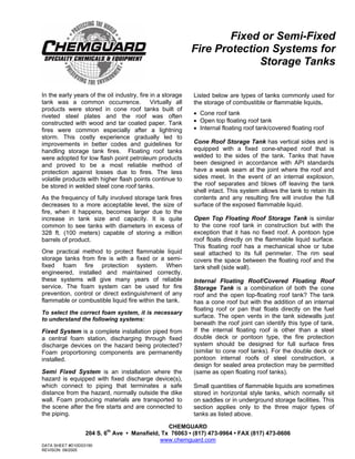
  • 1. Fixed or Semi-Fixed Fire Protection Systems for Storage Tanks In the early years of the oil industry, fire in a storage tank was a common occurrence. Virtually all products were stored in cone roof tanks built of riveted steel plates and the roof was often constructed with wood and tar coated paper. Tank fires were common especially after a lightning storm. This costly experience gradually led to improvements in better codes and guidelines for handling storage tank fires. Floating roof tanks were adopted for low flash point petroleum products and proved to be a most reliable method of protection against losses due to fires. The less volatile products with higher flash points continue to be stored in welded steel cone roof tanks. As the frequency of fully involved storage tank fires decreases to a more acceptable level, the size of fire, when it happens, becomes larger due to the increase in tank size and capacity. It is quite common to see tanks with diameters in excess of 328 ft. (100 meters) capable of storing a million barrels of product. One practical method to protect flammable liquid storage tanks from fire is with a fixed or a semi- fixed foam fire protection system. When engineered, installed and maintained correctly, these systems will give many years of reliable service. The foam system can be used for fire prevention, control or direct extinguishment of any flammable or combustible liquid fire within the tank. To select the correct foam system, it is necessary to understand the following systems: Fixed System is a complete installation piped from a central foam station, discharging through fixed discharge devices on the hazard being protected? Foam proportioning components are permanently installed. Semi Fixed System is an installation where the hazard is equipped with fixed discharge device(s), which connect to piping that terminates a safe distance from the hazard, normally outside the dike wall. Foam producing materials are transported to the scene after the fire starts and are connected to the piping. Listed below are types of tanks commonly used for the storage of combustible or flammable liquids. • Cone roof tank • Open top floating roof tank • Internal floating roof tank/covered floating roof Cone Roof Storage Tank has vertical sides and is equipped with a fixed cone-shaped roof that is welded to the sides of the tank. Tanks that have been designed in accordance with API standards have a weak seam at the joint where the roof and sides meet. In the event of an internal explosion, the roof separates and blows off leaving the tank shell intact. This system allows the tank to retain its contents and any resulting fire will involve the full surface of the exposed flammable liquid. Open Top Floating Roof Storage Tank is similar to the cone roof tank in construction but with the exception that it has no fixed roof. A pontoon type roof floats directly on the flammable liquid surface. This floating roof has a mechanical shoe or tube seal attached to its full perimeter. The rim seal covers the space between the floating roof and the tank shell (side wall). Internal Floating Roof/Covered Floating Roof Storage Tank is a combination of both the cone roof and the open top-floating roof tank? The tank has a cone roof but with the addition of an internal floating roof or pan that floats directly on the fuel surface. The open vents in the tank sidewalls just beneath the roof joint can identify this type of tank. If the internal floating roof is other than a steel double deck or pontoon type, the fire protection system should be designed for full surface fires (similar to cone roof tanks). For the double deck or pontoon internal roofs of steel construction, a design for sealed area protection may be permitted (same as open floating roof tanks). Small quantities of flammable liquids are sometimes stored in horizontal style tanks, which normally sit on saddles or in underground storage facilities. This section applies only to the three major types of tanks as listed above. CHEMGUARD 204 S. 6th Ave • Mansfield, Tx 76063 • (817) 473-9964 • FAX (817) 473-0606 www.chemguard.com DATA SHEET #D10D03190 REVISON: 09/2005
  • 2. CHEMGUARD 204 S. 6th Ave • Mansfield, Tx 76063 • (817) 473-9964 • FAX (817) 473-0606 www.chemguard.com IDENTIFY THE FLAMMABLE LIQUID There are two basic classifications of flammable and combustible liquids: • Hydrocarbon (non water miscible) • Polar Solvent (water miscible) Hydrocarbons include non water-soluble petroleum liquids such as crude oil, gasoline, jet fuels, fuel oils, etc. Polar solvents include water soluble liquids such as alcohols, ketones, esters etc. All Chemguard U.L. Listed and standard grade foam concentrates are suitable for use on hydrocarbon fuel fires or spills. Only Chemguard U.L. Listed and standard grade alcohol resistant AR-AFFF concentrates are suitable for use on polar solvent fuel fires or spills. NOTE: Pure MTBE is only slightly water miscible (approx. 4% - 6%). FLAMMABLE AND COMBUSTIBLE LIQUIDS PER NFPA 30 Flammable Liquid means liquid having a flash point below 100ºF (37.8ºC) and having a vapor pressure not exceeding 40 psi (276 kpa)(absolute) at 100ºF (37.8ºC) shall be known as a Class I liquid. Class I liquids shall be subdivided as follows: • Class IA includes those having flash points below 73ºF (22.8ºC) and having a boiling point below 100ºF (37.8ºC). • Class IB includes those having flash points below 73ºF (22.8ºC) and having a boiling point above 100ºF (37.8ºC). • Class IC includes those having flash points at or above 73ºF (22.8ºC) and below 100ºF (37.8ºC). Combustible Liquid means liquid having a flash point at or above 100ºF (37.8ºC). Combustible liquids shall be subdivided as follows: • Class II includes liquids with having flash points at or above 100ºF (37.8ºC) and below 140ºF (60ºC). • Class IIIA includes liquids with a flash points at or above 140ºF (60ºC) and below 200ºF (93.3ºC). • Class IIIB includes liquids with having flash points at or above 200ºF (93.3ºC). FIRE PROTECTION OF STORAGE TANKS U.L. has established two different types of foam discharge outlets: Type II Discharge Outlet - A fixed device that delivers foam onto the burning liquid and partially submerges the foam and produces restricted agitation of the surface. Examples of this type of device are Foam Chambers and Foam Makers. Type III Discharge Outlet - A fixed or portable device that delivers foam in a manner that causes the foam to fall directly onto the surface of the burning liquid in such a way that causes general agitation. Examples of this type of device are Hose Stream Nozzles and Monitors. Two basic methods of fire protection systems for storage tanks: • Sub-surface Base Injection • Over the Top - (Subdivided as follows) Foam Chambers, Foam Makers, Portable Foam Monitors and Foam Tower SUB-SURFACE BASE INJECTION The sub-surface method of fire protection produces foam with a HBPFM located outside the storage tank. This system delivers the expanded foam mass through piping into the base of the tank. The pipe may be an existing product line or can be a dedicated fire protection foam line. The expanded foam entering the tank through a discharge outlet is injected into the flammable liquid. The discharge outlet must be a minimum of 1 ft. above any water that may be present at the base of the tank. The foam will be destroyed if injected into the water layer. When injected into the fuel, the foam will rise through the fuel and form a vapor tight foam blanket on the fuel surface. Advantages of Sub-Surface • The rising foam can cause the fuel in the tank to circulate which can assist in cooling the fuel at the surface. • If there is an explosion and fire that could damage the top of the tank, the sub-surface injection system is not likely to suffer damage • The discharging foam is more efficiently directed to the fuel surface without any interruption from the thermal updraft of the fire. DATA SHEET #D10D03190 REVISON: 09/2005
  • 3. CHEMGUARD 204 S. 6th Ave • Mansfield, Tx 76063 • (817) 473-9964 • FAX (817) 473-0606 www.chemguard.com Disadvantages of Sub-Surface • CANNOT be used in storage tanks containing polar solvent type fuels or products that require the use of AR-AFFF type foam concentrates • Not recommended for use in either Floating Roof or Internal Floating Roof type tanks. • Caution must be used so that the maximum foam inlet velocity is not exceeded; otherwise, excessive fuel pickup by the foam as it enters the tank will be experienced. • Not to be used for protection of Class 1A hydrocarbon liquids HIGH BACK PRESSURE FOAM MAKER The HBPFM device is mounted in the foam line used to aspirate the foam solution before it is discharged into the storage tank base. It will typically give an expansion ratio of between 2:1 and 4:1. The device is capable of discharging against considerable backpressure, which can be as high as 40% of the operating pressure. The backpressure is an accumulation of head pressure in the fuel inside the storage tank and any friction loss between the foam maker and the tank. A minimum of 100-psi inlet pressure into the HBPFM is normally required to ensure correct operation. The foam velocity through the piping to the tank from the HBPFM is very critical. With flammable liquids, the foam velocity entering the tank should NOT exceed 10 ft. per second and with combustible liquids the foam velocity should NOT exceed 20 ft. per second. Following chart shows the minimum discharge times and application rates for sub-surface application: Hydrocarbon Type Fuel Minimum Minimum Discharge Application Time Rate Flash point between 100ºF 30 min. 0.10 gpm / ft. and 140ºF (37.8ºC and 93.3ºC) 4.1 L/min./m Flash point below 100ºF 55 min. 0.10 gpm / ft. (37.8ºC) liquids heated above 4.1 L/min./m their flash points. Crude Petroleum 55 min. 0.10 gpm / ft. 4.1 L/min./m NOTE: The maximum application rate shall be 0.20 gpm / ft. (8.1 L/min./m). FOAM CHAMBERS (TYPE II DISCHARGE DEVICE) The Foam Chamber is normally used on cone roof storage tanks. The chamber is bolted or welded on the outside of the tank shell near the roof joint. A deflector is mounted on the inside of the tank so that the discharging foam from the foam chamber will be diverted back against the inside of the tank wall. The foam chamber is mounted on the cone roof storage tank wall shell in a vertical position just below the roof joint, or approximately 8" to 12" down from the roof joint to the center point of the foam chamber outlet. In sequence Chemguard Models FC 2.5, 3, 4 and 6 foam chambers are to be mounted from approx. 8" to approx. 12” down from the roof joint. When the foam chamber is mounted correctly, the internal glass seal of the chamber will be just slightly higher in elevation than the roof joint on the storage tank. Each foam chamber mounted on a cone roof storage tank SHOULD have its own individually valved riser supplying the foam solution from outside the dike area. For correct operation, a minimum of 40 psi is required at the inlet to the foam chamber. FOAM MAKERS (TYPE II DISCHARGE DEVICE) The foam maker is normally used to aspirate foam solution before being discharged inside a dike (bund) area or when used with external floating roof tanks to supply foam to the rim seal area. The discharge pipe down stream of the foam maker is sized to slow the velocity of the expanded foam and shaped to deflect the foam back against the inside of the dike wall, onto a splash board, or onto the tank shell wall when used for floating roof seal protection. The splashboard is to be mounted above the top of the floating roof tank. The correct size discharge pipe from the foam maker should be installed per the information supplied in the dike protection system design information. When mounted on a storage tank or used in a dike protection system, the foam maker can be mounted in either a horizontal or a vertical position without any detrimental effect on foam performance. It is recommended that a minimum 12" length of straight pipe be installed upstream from the foam maker during the installation. When using the Chemguard Model CGFM 1.5 foam maker for a dike fire protection system, a 3" DATA SHEET #D10D03190 REVISON: 09/2005
  • 4. CHEMGUARD 204 S. 6th Ave • Mansfield, Tx 76063 • (817) 473-9964 • FAX (817) 473-0606 www.chemguard.com diameter pipe with minimum length of 28” and a maximum of 100" must be connected to the foam maker outlet (down stream side). This length of discharge pipe allows the correct foam expansion to take place and slows the discharge velocity. The CGFM 2.5 Foam Maker requires a length of 4" pipe to be connected to the discharge side of the maker. This length of pipe should also be a minimum of 28" but can have a maximum length of 120". The discharge pipe in both instances should be directed back against the inside wall of the dike. This installation allows a more gentle application to the flammable liquid within the dike and lessens the submergence of the foam. Criteria for sizing a system for a cone roof tank 1. Identify the fuel inside the tank 2. Type of foam concentrate to be used 3. Calculate the fuel surface area (TTR2 ) 4. Application rate 5. Type of discharge device required and quantity (based on fuel flash point and tank diameter) 6. Calculate discharge duration 7. Supplementary hose lines required and discharge duration 8. Quantity of foam concentrate required 9. Establish bill of materials NOTE: To determine the quantity of foam concentrate in a given quantity of foam solution, use the following formula: Multiply the foam solution by x .01 if using a 1% type of concentrate x .03 if using a 3% type of concentrate x .06 if using a 6% type of concentrate EXAMPLE: Cone roof tank: 150 ft. diameter Fuel: Gasoline Foam Concentrate: 3% AFFF Surface Area: 75'x75' x 3.1417 = 17,672 sq. ft. Application Rate @ .10 gpm per sq. ft. (Per NFPA 11) .10 x 17,672 sq. ft. = 1,767.2 gpm of foam solution required Discharge Device: Foam Chamber, Qty. 4 Discharge Duration: 55 min. 1,767.2 x 55 = 97,196 gallons of foam solution x .03 = 2,915.88 gallons of 3% AFFF concentrate required. Supplementary hose lines required: Qty. 3 (per NFPA 11) each minimum 50 gpm. tank dia. over 120 ft. Hose line discharge duration: 30 min. (Per NFPA 11) Tank dia over 95 ft. 3 x 50 = 150 x 30 = 4,500 gal. of foam solution x .03 = 135 gallons of 3% AFFF. 3,051 (135+2,916) gallons of foam concentrate A suitable bill of materials of major components for the above system using a bladder tank could be the following: • 1 x 3,200 gallon horizontal style bladder tank • 1 x 6” Between flange style ratio controller • 4 x 6” foam chamber each with a flow rate of 395 to 1,050 gpm depending on incoming pressure • 1 x 2-1/2” Threaded type ratio controller (For supplementary system). • 3 x 50 gpm handline nozzles • Foam concentrate NOTE: This chart identifies the number of Foam Chambers required for the protection of a flammable liquid contained in a vertical cone roof atmospheric storage tank where the discharge device is attached to the tank. Where two or more outlets are required, the outlets are to be equally spaced around the tank periphery and each outlet is to be sized to deliver foam at approximately the same rate. Tank Diameter Meters Minimum Number (or equivalent of discharge area) outlets Up to 80 ft. 24 1 Over 80 to 120 24 to 36 2 Over 120 to 140 36 to 42 3 Over 140 to 160 42 to 48 4 Over 160 to 180 48 to 54 5 Over 180 to 200 54 to 60 6 It is suggested that for tanks above 200 ft. (60 m) in diameter at least one additional discharge outlet be added for each additional 5,000 sq. ft. (465 sq. m.) of liquid surface or fractional part. This chart indicates the number of SUPPLEMENTARY hose streams required for various size tanks. Each hose stream must be capable of a minimum flow rate of 50 gpm of foam solution. Diameter of Largest Tank Minimum # of hose streams req’d Up to 65 ft. (19.5 m) 1 65 to 120 ft. (19.5 to 36 m) 2 Over 120 ft. (36 m) 3 This chart shows the Minimum discharge time and DATA SHEET #D10D03190 REVISON: 09/2005
  • 5. CHEMGUARD 204 S. 6th Ave • Mansfield, Tx 76063 • (817) 473-9964 • FAX (817) 473-0606 www.chemguard.com application rate for Type II fixed foam discharge devices on Cone Roof storage tanks. Hydrocarbon Type Application Discharge Rate Time Flash point between 0.10 gpm/ft. 30 min. 100ºF and 140ºF 4.1 L/min./m (37.8ºC and 93.3ºC) Flash point below 100º 0.10 gpm/ft. 55 min. (37.8ºC) or liquids heated 4.1 L/min./m above their flash points Crude Petroleum 0.10 gpm/ft. 55 min. 4.1 L/min./m Flammable liquids having a boiling point of less than 100ºF might require higher rates of application. These should be determined by test. For high-viscosity liquids heated above 200ºF, lower initial rates of application of foam may be desirable to minimize frothing and the subsequent expulsion of the stored liquid from the storage tank. Good judgment should be used in applying foams to tanks containing hot oils, burning asphalts or burning liquids that have boiling points above the boiling point of water. The above table includes gasohols and unleaded gasolines containing no more than 10% oxygenated additives by volume. Where these additives exceed 10% by volume, or where the flammable liquid is a polar solvent or water miscible product, fire protection for polar solvents and water miscible products must be used, such as Chemguard CUG 3% AR-AFFF or other AR-AFFF concentrate. The minimum discharge duration is 55 minutes. The following chart indicates the minimum operating time of the supplementary hose stream(s) for various size tanks. Diameter of Largest Tank Minimum Operating Time Up to 35-ft. (10.5 m) 10 min. 35 to 95 ft. (10.5 to 28.5 m) 20 min. Over 95 ft. (28.5 m) 30 min. Below is an equipment list using a Foam Pump Skid assembly for a 150 ft. dia. tank containing gasoline. • 1 x Atmospheric Foam Concentrate Storage Tank 3100 Gallons • 1 x Electric powered Foam Pump Proportioning Skid with prepiped 6" ratio controller (Foam Chambers) and prepiped 2 1/2" ratio controller (Supplementary Hose Lines) • 4 x Model FC4 or FC6 Foam Chambers • 3 x 50 gpm Handline nozzles • 3,051 x Gallons 3% AFFF (plus any additional for testing of the system) NOTE: When protecting multiple storage tanks the foam system is to be sized to protect the single largest hazard. Figure 9: Depicts a manual foam pump skid system showing all necessary piping, valves, discharge devices, ratio controller, foam pump and foam storage tank for the above system. Figure 10: Shows a Cone Roof Storage Tank with a Semi-Fixed Foam System. The following example shows the foam system requirements for seal protection of a 150 ft. diameter open top floating roof tank. Type of Tank: Open Top Floating Roof Tank Diameter of Tank: 150 ft. Type of Fuel: Gasoline Foam Dam installed on roof: Yes - 2 ft. from tank wall and 2 ft. in height Sq. ft. area of annular ring: 930 sq. ft. Application Rate: .30 gpm per sq. ft. (Per NFPA 11). 30 x 930 sq. ft. = 279 gpm of foam solution required. Discharge Device: Foam Makers discharge duration is 20 min. 279 x 20 = 5580 gallons of foam solution 5580 x .03 (3% AFFF) = 167.4 gallons of foam concentrate Foam Makers: Qty. 6 (Per NFPA 11) Add supplementary hose lines per example for Cone Roof Tank with Foam Chambers. NOTE: The number of fixed foam discharge points on an open top floating roof tank is determined by the circumference of the tank. The maximum spacing between discharge points is 40 ft. (12.2 m) of tank circumference when using a 12" (305 mm) high foam dam and every 80 ft. (24.4 m) of tank circumference when using a 24" (610 mm) high foam dam. In accordance with NFPA 11 Appendix B Storage Tank Protection Summary. FOAM DAM DESIGN - The foam dam should be circular and constructed of at least No. 10 US Standard Gage Thickness (.134 in./3.4 mm) steel plate. The dam is to be welded or otherwise securely fastened to the floating roof. The foam dam is designed to retain foam at the seal area at a DATA SHEET #D10D03190 REVISON: 09/2005
  • 6. CHEMGUARD 204 S. 6th Ave • Mansfield, Tx 76063 • (817) 473-9964 • FAX (817) 473-0606 www.chemguard.com sufficient depth to cover the seal area while causing the foam to flow laterally to the point of seal rupture. Dam height is to be at least 12" (305 mm) and should extend at least 2" (51 mm) above any metal secondary seal or a combustible secondary seal using a plastic foam log. It is to be at least 2" (51 mm) higher than any burnout panels in metal secondary seals. Foam dams are to be at least 1 ft. (0.3 m) but no more than 2 ft. (0.6 m) from the edge of the floating roof. Foam solution and rain water is to be drained by, slotting the bottom of the dam on the basis of 0.04 sq. in. of slot area per sq. ft. (278 mm sq./sq. m) of diked area while restricting the slots to 3/8 in. (9.5 mm) in height. Excessive dam openings for drainage should be avoided to prevent loss of foam through the drainage slots. SUB-SURFACE SYSTEM Sub-surface injection of foam is generally not recommended for fuels that have a viscosity greater than 2,000 ssu (440 centistokes) at their minimum anticipated storage temperature. Example: Cone Roof Tank: 80 ft. diameter Fuel: Gasoline Foam Concentrate: 3%-6% AR-AFFF Surface Area: 40' x 40' x 3.1417 = 5,026.7 sq. ft. Application Rate: .10 gpm per sq. ft.(.10 x 5,027 sq. ft. = 502.7 gpm of foam solution Discharge Duration: 55 min. Foam Concentrate: 503 x 55 x .03 = 829.95 gallons Discharge Device: Qty 1 High-Back Pressure FM Discharge outlets inside tank: Qty 1 (Tank 80 ft. or less) Per NFPA 11 Supplementary hose lines for Cone Roof Tank The following chart shows the number of discharge outlets required inside the tank. Tank Diameter Number of Discharge Outlets Required Flash Point below Flash Point 100ºF 100ºF (38ºC) (38ºC) or Higher Up to 80 ft. (24 m) 1 1 Over 80 to 120 ft. (24 -36 m) 2 1 Over 120 to 140 ft.(36-42 m) 3 2 Over 140 to 160 ft.(42-48 m) 4 2 Over 160 to 180 ft.(48-54 m) 5 2 Over 180 to 200 ft.(54-60 m) 6 3 Over 200 ft. (60 m) 6 3 Plus 1 outlet for Plus 1 outlet for each additional each additional 5,000 sq. ft. 7,500 sq. ft. (465 sq. m) (697 sq. m) Equipment list for the above example using bladder tank foam supplied foam system. • 1 x 900 Gallon vertical style bladder tank • 1 x 2½" Threaded type ratio controller (for supplementary hose lines) • 1 x 4” Between flange style ratio controller • 1 x 500 gpm High Back Pressure Foam Maker • Supplementary handline nozzles and foam concentrate Determining Number of Discharge Outlets for Sub-surface Base Injection The number of discharge outlets required is based on the tank diameter and the flash point of the fuel as shown in the above chart. Foam Monitors and Handlines Monitors are not to be considered as the primary means of protection for fixed roof tanks over 60 ft. in diameter. Foam handlines are not to be considered as the primary means of protection for tanks over 30 ft. in diameter or for those over 20 ft. in height. Application Rates Using Monitors/Handlines The minimum foam solution application rate is based on the assumption that all discharging foam will reach the area being protected. In considering actual solution flow requirements, consideration should be given to potential foam losses from climatic conditions, thermal updraft of the fire, etc. The following chart shows application density and duration for monitors and handlines on tanks containing hydrocarbons. Hydrocarbon Type Minimum Minimum Application Rate Discharge gpm/ft 2 (L/min.)/m 2 Time (min.) Flash point between 100ºF and 140ºF (37.8ºC and 93.3ºC) 0.16 6.5 50 Flash point below 100ºF (37.8ºC) or liquids heated above their flash point 0.16 6.5 65 Crude Petroleum 0.16 6.5 65 Included in the above table are gasohols and unleaded gasolines containing no more than 10 percent of an oxygenated additive by volume. DATA SHEET #D10D03190 REVISON: 09/2005
  • 7. CHEMGUARD 204 S. 6th Ave • Mansfield, Tx 76063 • (817) 473-9964 • FAX (817) 473-0606 www.chemguard.com On tanks containing water miscible/polar solvent flammable liquids the recommended foam application duration is 65 minutes. Flammable liquids having a boiling point less than 100ºF and products that have been burning for some time can develop a heat layer which might require foam solution application rates as high as .2 or .25 gpm per sq. ft. Where monitors or handlines are used to protect storage tanks containing polar solvent or water miscible liquids the discharge duration shall be a minimum of 65 minutes at the recommended application rate. DATA SHEET #D10D03190 REVISON: 09/2005
  • 8. CHEMGUARD 204 S. 6th Ave • Mansfield, Tx 76063 • (817) 473-9964 • FAX (817) 473-0606 www.chemguard.com FIGURE 9 DATA SHEET #D10D03190 REVISON: 09/2005
  • 9. CHEMGUARD 204 S. 6th Ave • Mansfield, Tx 76063 • (817) 473-9964 • FAX (817) 473-0606 www.chemguard.com FIGURE 10 DATA SHEET #D10D03190 REVISON: 09/2005
  • 10. CHEMGUARD 204 S. 6th Ave • Mansfield, Tx 76063 • (817) 473-9964 • FAX (817) 473-0606 www.chemguard.com DATA SHEET #D10D03190 REVISON: 09/2005