1. 3.2.2-Band Pass Filter:
A band-pass filter is a circuit which is designed to pass signals only in a certain band of
frequencies while attenuating all signals outside this band. The parameters of importance in a
band pass filter are the high and low cut-off frequencies (fH and fl), the bandwidth (BW), the
centre frequency fc, centre-frequency gain, and the selectivity or Q.
There are basically two types of BandPass filters :
3.2.2.1-Wide Band pass Filter:
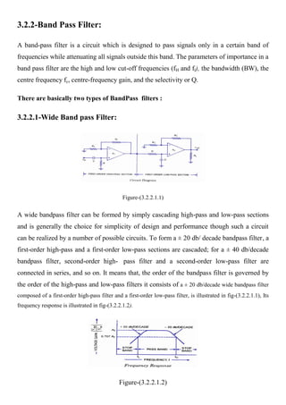
Figure-(3.2.2.1.1)
A wide bandpass filter can be formed by simply cascading high-pass and low-pass sections
and is generally the choice for simplicity of design and performance though such a circuit
can be realized by a number of possible circuits. To form a ± 20 db/ decade bandpass filter, a
first-order high-pass and a first-order low-pass sections are cascaded; for a ± 40 db/decade
bandpass filter, second-order high- pass filter and a second-order low-pass filter are
connected in series, and so on. It means that, the order of the bandpass filter is governed by
the order of the high-pass and low-pass filters it consists of a ± 20 db/decade wide bandpass filter
composed of a first-order high-pass filter and a first-order low-pass filter, is illustrated in fig-(3.2.2.1.1), Its
frequency response is illustrated in fig-(3.2.2.1.2).
Figure-(3.2.2.1.2)
2. Filter Desing :
1- Choose a value of high cutoff frequency fH
and low cutoff frequency fL
2- select a value of C
3- Calculate the value of R for LPF and R for HPF using
for LPF R=
for HPF R=
4- select value of R1 and Rf dependent on the desired passband gain Af using
Af = 1+
Experiment of BPF:
Figure-(3.2.2.1.3) Band pass Filter For (500) KHz Figure-(3.2.2.1.4) Output Of BPF At (500) KHz
3. 3.2.2.2-Narrow Band Pass Filter:
Figure-(3.2.2.2)
A narrow bandpass filter employing multiple feedback is depicted in figure. This filter
employs only one op-amp, as shown in the figure. In comparison to all the filters discussed
so far, this filter has some unique features that are given below.
1. It has two feedback paths, and this is the reason that it is called a multiple-feedback filter.
2. The op-amp is used in the inverting mode.
The frequency response of a narrow bandpass filter is shown in fig(b).
Generally, the narrow bandpass filter is designed for specific values of centre frequency fc
and Q or fc and BW. The circuit components are determined from the following relation-
ships. For simplification of design calculations each of C1 and C2 may be taken equal to C.
R1 = Q/2 fc C Af, R2 = Q / 2 fc C (2Q2 Af), R3 = Q / fc C
where Af , is the gain at centre frequency and is given as
Af = R3 / 2R1
The gain Af however must satisfy the condition Af < 2 Q2.
The centre frequency fc of the multiple feedback filter can be changed to a new frequency fc‘
without changing, the gain or bandwidth. This is achieved simply by changing R2 to R’2 so
that R’2 = R2 [fc/f c]2