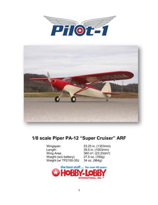
3. Hobby-Lobby.com is pleased to announce the 1/8 scale Piper PA-12 “Super Cruiser” as
part of its Pilot-1 Golden Age Civilian Series. The Pilot-1 “Super Cruiser” encompasses
the same attributes in quality construction and handling that made the original a great
design. We know you will be pleased with your new model. Its’ beautiful looks, balanced
maneuverability, and docile flying characteristics make it a design that is truly at home
cruising the skies at a Pilot-1 Aerodrome near you!
Hobby Lobby International, Inc.
5614 Franklin Pike Circle
Brentwood, TN 37027
1-866-WE-FLY-RC
(1-866-933-5972)
www.hobby-lobby.com
3
4. Introduction & History
“The end of World War II saw the resumption of private aircraft manufacture and the
Piper Aircraft Company, already well known for the J-3 Cub and the J-5 Cruiser, began
production of improved models of these aircraft. These were the Piper PA-11 Cub
Special and the Piper PA-12 Super Cruiser. Walter Jamoneau, who was head of the
engineering department at Piper for many years, modified the J-5 into the PA-12. Test
flights were made in December 1945, and the first production version of the aircraft
appeared in February 1946.”
“The original J-5 series were fabric-covered, three-place, high-wing monoplanes, initially
powered by 75-hp Lycoming engines, and later by 90-hp Lycomings. The PA-12 was
also fabric-covered, over a welded metal tubular frame and wooden wing spars, and
featured a Lycoming O-325-C engine, fully cowled. Later models of the PA-12 had as
optional equipment a slightly more powerful engine. Standard features on the PA-12
included an electric starter, navigation lights, and a cabin heater. The Piper PA-12
Super Cruiser was used in a number of roles, from private pleasure flying to light cargo
carrying and many are still flying. It was also successful in the export market.”
Manufacturer: Piper Aircraft Corp.
Date: 1946
Country of Origin: United States of America
Dimensions:
Wingspan: 10.8 m (35 ft 5 in)
Length: 6.86 m (22 ft 6 in)
Height: 2.08 m (6 ft 10 in)
Weight, empty: 454 kg (1,000 lb)
Weight, gross: 793 kg (1,750 lb)
Top Speed: 184 km/h (115 mph)
Engine: Lycoming O-235-C, 100 hp
Materials:
Fuselage: steel tube with fabric cover
Physical Description:
Single engine, two seat, high wing, monoplane, [cream] and red, first light aircraft to fly around the world
(Source: Online, NASM, http://www.nasm.si.edu/ , Jan 3, 2009) Search “Piper Super Cruiser” at the
following link: http://www.nasm.si.edu/
4
5. Before starting, use the contents list to take an inventory and make sure it is complete.
If any parts are missing or are not of acceptable quality, contact Hobby-Lobby.com
support at 1-866-WE-FLY-RC (1-866-933-5972)
Contents List
Fuselage
Battery Hatch
Engine Cowl
Landing Gear
Wheels, Velcro, Tailwheel, Misc Hardware
Windshield and Side Windows
Wings, Center Section, and Ailerons
Tube Wing Joiner and Wing Struts
Horizontal Tail
Vertical Tail
Pushrods
Additional Items Required
4-channel Aircraft Radio w/ Receiver (minimum), Computer radio recommended.
2100 mah, 3-cell, 11.1v Lipo Battery (1800-2200mah)
(4) Hitec HS-55 Servos
18 amp Jeti Advance Plus Brushless ESC
AXI 2217/16 Brushless Motor
AXI 22 Series Radial Mount
APC 9x6SF “Slow-fly” Propeller
Soldering Iron and Electrical Solder
5-minute Epoxy Glue
Thin CA Glue and Canopy Glue (craft glue)
Small Phillips Screwdriver
Needle Nose Pliers
Hobby Knife
5
6. 1. This manual will help you assemble your
Hobby-Lobby.com Pilot-1 airplane step-by-
step. It does assume that this is not your
first airplane. If you need assistance, please
ask a local flyer, visit www.rcgroups.com, or
call us here at Hobby-Lobby.com. Let’s start
by preparing the aileron servos and aileron
wire extensions. Wrap the connection with
tape or use heat shrink tubing to prevent an
accidental disconnect.
2. Make sure servo is centered and install
large servo horn and screw. Test fit servo
on servo cover.
3. While holding servo horn centered in the
slot, use 5-min epoxy to glue servo blocks
in place as shown. Be careful to align side-
to-side and up-and-down.
4. After 5-min epoxy has set, install servo
screws into blocks. Use wire cutters to
remove unused side of servo arm.
6
7. 5. Insert the elevator or rudder pushrod into
the wing so that it sticks out of the aileron
servo cavity as shown. Note: Be careful not
to bend pushrod.
6. Tape the aileron wire extension to the end
of the pushrod. Pull pushrod and wire
through wing panel. Remove tape from
pushrod. Repeat for opposite wing panel.
7. Install each aileron servo cover with four (4)
small sheet metal screws.
8. Bend CA hinges as shown. Flex hinges
completely back and forth several times to
loosen them before installation.
7
8. 9. Insert CA hinges and aileron into wing.
Make sure alignment is good with even
spaces at each end of aileron.
10. With aileron deflected downward and fitted
with no gap between the leading edge of
aileron and wing, CA each hinge. Use thin
CA, 2 drops per hinge per side.
11. Insert wing tube and route aileron wire as
shown.
12. Insert machine screw and washer into
predrilled hole to secure wing panel.
8
9. 13. Use straight edge and pen to mark where
the aileron control horn will be attached.
14. Make another mark 8mm (5/16”) as shown.
This is where the aileron horn pins will go
through the balsa aileron block.
15. Temporarily insert aileron control horn into
aileron.
16. Trace around horn and remove covering
with hobby knife.
9
10. 17. Insert horn and use thin CA or 5-min epoxy
to glue in place.
Repeat steps 1-17 for opposite wing
panel.
18. Insert aileron pushrod “z-bend” into outer
hole of servo arm as shown. You may need
to use a drill bit, reamer, or hobby knife to
enlarge hole in servo arm.
19. Adjust clevis to correct length and connect
to aileron horn. Slide fuel tubing safety onto
clevis to prevent accidental disconnect.
20. Look at the covering on the horizontal
stabilizer to determine which side is the top.
Use a pen to mark the “top.”
TOP
10
11. 21. Using the same technique as the ailerons to
install the elevator. Pre-bend the CA
hinges, deflect downwards, CA each hinge
2 drops per side. *Note: before gluing, if you
feel hinges are too stiff, cut each hinge in
half so that they are 1/4” wide by 1/2" long.
Then glue normally.
22. Temporarily install the wing. Insert
countersunk machine screws or use
masking tape to hold in place.
23. Temporarily install horizontal and vertical
stabilizers in place.
24. Use 90 degree square to align vertical
stabilizer. Check alignment between
horizontal stabilizer and wing for level.
Measure left and right elevator tip to aileron
tip and adjust so that they are even. Some
twist can be removed with light heating of
covering with heat gun.
11
12. 25. When completely satisfied with fit and
alignment, use thin CA to glue each joint
thoroughly. There are six joints total.
26. Remove covering from lower front of
rudder. Insert and glue tailwheel wire into
predrilled hole. Use 5-min epoxy for this
step.
27. Install rudder and check for alignment.
28. Use thin CA for each hinge as you did with
the elevator. Be careful NOT to CA the
tailwheel bracket to the tailwheel wire.
12
13. 29. Install pushrods and servos as shown.
Make sure servos are centered before
installing horns. The outer holes may need
to be drilled out slightly for the “z-bend” in
the wire.
30. Install pushrod clevis to the rudder and
elevator pushrods. Use a sheet metal screw
to install tailwheel bracket. NOTE: fuel
tubing safety shown installed on clevis.
31. Measure and mark a line 9mm (5/16”) from
the hinge line. Install control horn on clevis.
32. Lightly press control horn points into
elevator along mark made in previous step.
13
14. 33. Using the indentations, drill two pilot holes
through elevator. The drill bit should be
smaller than the control horn pin diameter,
approximately 1.5mm (1/16”).
34. Trace around horn, remove the covering,
install control horn flush.
35. Use thin CA on both sides of elevator to
secure horn in place. Then use wire cutters
to trim of excess pin length flush. NOTE:
Make sure to use fuel tubing over each
clevis to prevent them from coming open
accidentally.
36. Repeat the steps above for the ruder horn.
Again, make sure to install the fuel tubing
safety sleeve on each clevis.
14
15. 37. Install four (4) aluminum straps and eight
(8) sheet metal screws on each corner of
landing gear wire as shown. Install wheels
and wheel collars.
38. Solder motor to speed control. In our
application, on the motor side of the ESC,
connect black to yellow, red to red, yellow
to black. That will assure motor runs the
correct direction. Solder your battery
connector on the other end of ESC. Here
we have used the Male Deans Ultra plug.
As with any electric plane, use high quality
connectors designed for R/C applications
and make good solder connections.
39. Install motor mount supplied in AXI
accessory kit. Then install motor mount
bolts with plywood spacers as shown.
40. Use tie wraps or tape to secure ESC
(Electronic Speed Control) to motor box.
Route wires as necessary to receiver and
battery.
15
16. 41. Cut four (4) strips of paper the same width
of cowling blocks (approx. 1/2” wide) and 4”
long. Use tape to install paper strips over
each cowling block as shown.
42. Install cowling. Make sure the paper strips
are on outside of cowl. Align cowl with
propeller shaft face 5mm (3/16”) in front of
cowl. Use masking tape to hold cowl in
position for next few steps.
43. Use a pen to mark the location for each
screw on the paper strips.
44. Drill a 1mm (1/32”) pilot hole through paper
strip, cowl, and wood mounting blocks for
each of the four (4) screws.
16
17. 45. Fold paper strips out of the way and slightly
enlarge the hole in the fiberglass cowl only!
Here we are using a reamer but you could
use a hobby knife or drill bit. This is done to
keep cowl from cracking when inserting the
cowl sheet metal screws.
46. Install four (4) sheet metal screws to hold
cowl in place. Remove all tape and paper
strips. Install the APC 9x6SF propeller. An
APC “E-series” is shown in this photo but
we preferred the “SF-series” after testing.
47. Install receiver and hook up all servos and
wiring. A 2.4GHz receiver is shown here. If
you are using a 72MHz radio, you may wish
to route antenna though bottom of plane,
along belly, and use clear tape to secure
near tailwheel, leaving any extra wire to trail
behind plane.
48. We used a black permanent marker to color
around window frames before installing
windows.
17
18. 49. Use canopy glue or craft glue to install side
windows.
50. Use canopy glue to install windshield. Use a
wet paper towel to clean up any mess
before glue dries. Use masking tape to hold
everything in place while the glue dries.
51. Make one (1) loop with the tail brace cable
and crimp. Compress crimp with needle
nose pliers as shown.
52. Remove tailwheel bracket screw and
reinstall with wire loop from above step.
Route tail brace cable through predrilled
holes in horizontal and vertical stabilizers,
then through 2nd crimp, around screw, and
back through crimp as shown. Then lightly
pull slack out of cable and compress crimp
with needle nose pliers. Trim off extra
cable.
18
19. 53. The tail brace cable should look like this
when complete.
54. Prepare the wing struts for assembly. The
front strut is slightly larger than the rear
strut.
55. Place scrap foam or towel under center
section of wing for support. You do not want
any load placed on wing tips while installing
struts. Sight the wings from behind the
airplane to check for any warp or twist. If
any is found, twist wing back to straight and
lightly use heat gun or iron to remove any
wrinkles in covering. Experienced modelers
may want to add a degree or two of
washout (L.E. down) at the wing tips.
56. Install both wing struts to the fuselage with
sheet metal screws behind the landing gear
as shown.
19
20. 57. When you are satisfied with the
straightness of the wing, use a sheet metal
screw to attach the forward wing strut at 1-
5/8” (41mm) from the Leading Edge of the
wing.
58. Install a sheet metal screw in the rear strut
at 5-3/8” (137mm) from the Leading Edge of
the wing.
59. You may wish to remove struts and soak
each hole with thin CA to strengthen attach
point. Reinstall sheet metal screws after CA
has dried.
60. Make a mark on each wing 2” (50mm) back
from the leading edge. Install battery and
balance model at these marks with the tips
of your fingers. Move the battery fore or aft
until airplane balances with fuselage level
or slightly nose down. Make a mark in CG
battery compartment so that you place the
battery in the same place every time. Small
stick-on lead weights may also be
necessary inside engine cowl or near tail to
properly balance.
20
21. 61. Please refer to your radio manual for the
following few steps. Please note that some
computer radios have separate settings for
exponential for high and low rate positions.
Make sure you double check all settings
before flight. If you are new to
programming, check with a local
experienced modeler or hobby shop for
assistance. The use of Exponential (expo)
and Aileron-Rudder mix is recommended.
62. Adjust Elevator HIGH RATE travel to get
7/8” (22mm) up and 7/8” (22mm) down.
Use 25% expo to soften the center travel
22mm
per your radio manual. (JR/Spektrum +25%
and Futaba/Hitec -25%)
22mm
63. Adjust Elevator LOW RATE travel to get
9/16” (15mm) up and 9/16” (15mm) down
travel.
Use 20% expo to soften the center travel 15mm
per your radio manual. (JR/Spektrum +20% 15mm
and Futaba/Hitec -20%)
64. Adjust Rudder HIGH RATE travel to get
3/4” (20mm) left and 3/4" (20mm) right
Use 25% expo to soften the center travel
per your radio manual. (JR/Spektrum +25%
and Futaba/Hitec -25%).
20mm 20mm
21
22. 65. Adjust Rudder LOW RATE travel to get
9/16” (15mm) LEFT and 9/16" (15mm)
RIGHT.
Use 20% expo to soften the center travel
per your radio manual. (JR/Spektrum +20%
and Futaba/Hitec -20%).
15mm 15mm
66. Adjust each aileron’s HIGH RATE travel to
get 9/16” (14mm) UP and 3/16” (6mm)
DOWN using the end point adjustment.
14mm
Use 25% expo to soften the center travel 6mm
per your radio manual. (JR/Spektrum +25%
and Futaba/Hitec -25%)
67. Adjust each aileron’s LOW RATE travel to
get 7/16” (11mm) UP and 1/16” (4mm)
DOWN using the end point adjustment.
11mm
Use 20% expo to soften the center travel
per your radio manual. (JR/Spektrum +20% 4mm
and Futaba/Hitec -20%)
68. The use of a very small Aileron-to-Rudder
mix is also suggested. We used a mix of
12%. This means when you move the
aileron control stick to its full position, the
rudder will also move about 3/16” (5mm) in
the same direction of the control stick.
22
23. Preflight
If you are new to flying R/C aircraft, or a seasoned modeler, we recommend you have a
fellow R/C modeler help you with the first flight. Some items you will need to complete
on your first preflight are:
1. Aircraft assembled correctly and ready for flight.
2. All control throws and expos are set per this manual.
3. Transmitter fully charged and on correct model.
4. Aircraft balances at the recommended location. (2” aft of wing Leading Edge)
5. Flight Battery is fully charged and secure.
6. All electronics are operating correctly, proper direction, and secure.
7. Complete a radio Range Check per your radio manual.
8. Balance propeller and make sure it is secure.
9. Wait for a calm or light wind day for first flights.
10. If you are new to R/C flying, consider having an accomplished flyer make the first
flight and trim the aircraft. A buddy-box training system is also very helpful.
Flying
You will soon find out the Pilot-1 “Super Cruiser” is a real pleasure to fly. Takeoffs,
landings, and light aerobatics are easy and well behaved. Even if you have never flown
a tailwheel airplane before, the Pilot-1 “Super Cruiser” should be an easy transition. We
personally recommend the use of a buddy-box training system for new pilots. Landings
are best accomplished by “three-pointing.” This means that all three wheels should
touch at the same time and a little up-elevator is held until the aircraft comes to a
complete stop. Except for takeoff and climb, you will only use about 1/2 throttle to
maintain a scale flying speed. You can expect flight times of 15-20 minutes depending
on battery used and throttle management.
We hope you enjoy your Pilot-1 “Super Cruiser” as much as we do!
Happy Landings!
WARNING – THIS IS NOT A TOY!
Radio controlled model aircraft are capable of inflicting serious injury and/or property damage if not assembled, operated, and
maintained in a competent and safe manner. If you are not already experienced with radio controlled models, we strongly suggest
that you find an experienced modeler to assist you.
Warranty
Hobby-Lobby guarantees this kit to be free from defects in both material and workmanship at the date of purchase. This warranty
does not cover any component parts damaged by use or modification. In no event shall Hobby-Lobby’s liability exceed the original
cost of the purchased kit.
Completely read through this manual before starting construction.
23
26. 2008 Official Academy of Model Aeronautics National Model Aircraft Safety Code
GENERAL
1. A model aircraft shall be defined as a non-human-carrying device capable of sustained flight in
the atmosphere. It shall not exceed limitations established in this code and is intended to be used
exclusively for recreational or competition activity.
2. The maximum takeoff weight of a model aircraft, including fuel, is 55 pounds, except for those
flown under the AMA Experimental Aircraft Rules.
3. I will abide by this Safety Code and all rules established for the flying site I use. I will not willfully
fly my model aircraft in a reckless and/or dangerous manner.
4. I will not fly my model aircraft in sanctioned events, air shows, or model demonstrations until it
has been proven airworthy.
5. I will not fly my model aircraft higher than approximately 400 feet above ground level, when within
three (3) miles of an airport without notifying the airport operator. I will yield the right-of-way and
avoid flying in the proximity of full-scale aircraft, utilizing a spotter when appropriate.
6. I will not fly my model aircraft unless it is identified with my name and address, or AMA number,
inside or affixed to the outside of the model aircraft. This does not apply to model aircraft flown
indoors.
7. I will not operate model aircraft with metal-blade propellers or with gaseous boosts (other than
air), nor will I operate model aircraft with fuels containing tetranitromethane or hydrazine.
8. I will not operate model aircraft carrying pyrotechnic devices which explode burn, or propel a
projectile of any kind. Exceptions include Free Flight fuses or devices that burn producing smoke
and are securely attached to the model aircraft during flight. Rocket motors up to a G-series size
may be used, provided they remain firmly attached to the model aircraft during flight. Model
rockets may be flown in accordance with the National Model Rocketry Safety Code; however,
they may not be launched from model aircraft. Officially designated AMA Air Show Teams (AST)
are authorized to use devices and practices as defined within the Air Show Advisory Committee
Document.
9. I will not operate my model aircraft while under the influence of alcohol or within eight (8) hours of
having consumed alcohol.
10. I will not operate my model aircraft while using any drug which could adversely affect my ability to
safely control my model aircraft.
11. Children under six (6) years old are only allowed on a flightline or in a flight area as a pilot or
while under flight instruction.
12. When and where required by rule, helmets must be properly worn and fastened. They must be
OSHA, DOT, ANSI, SNELL or NOCSAE approved or comply with comparable standards.
RADIO CONTROL
1. All model flying shall be conducted in a manner to avoid over flight of unprotected people.
2. I will have completed a successful radio equipment ground-range check before the first flight of a
new or repaired model aircraft.
3. I will not fly my model aircraft in the presence of spectators until I become a proficient flier, unless
I am assisted by an experienced pilot.
4. At all flying sites a line must be established, in front of which all flying takes place. Only personnel
associated with flying the model aircraft are allowed at or in front of the line. In the case of
airshows demonstrations straight line must be established. An area away from the line must be
maintained for spectators. Intentional flying behind the line is prohibited.
5. I will operate my model aircraft using only radio-control frequencies currently allowed by the
Federal Communications Commission (FCC). Only individuals properly licensed by the FCC are
authorized to operate equipment on Amateur Band frequencies.
6. I will not knowingly operate my model aircraft within three (3) miles of any preexisting flying site
without a frequency-management agreement. A frequency management agreement may be an
(continued)
26
27. allocation of frequencies for each site, a day-use agreement between sites, or testing which
determines that no interference exists. A frequency-management agreement may exist between
two or more AMA chartered clubs, AMA clubs and individual AMA members, or individual AMA
members. Frequency-management agreements, including an interference test report if the
agreement indicates no interference exists, will be signed by all parties and copies provided to
AMA Headquarters.
7. With the exception of events flown under official AMA rules, no powered model may be flown
outdoors closer than 25 feet to any individual, except for the pilot and located at the flightline.
8. Under no circumstances may a pilot or other person touch a model aircraft in flight while it is still
under power, except to divert it from striking an individual.
9. Radio-controlled night flying is limited to low-performance model aircraft (less than 100 mph). The
model aircraft must be equipped with a lighting system which clearly defines the aircraft's attitude
and direction at all times.
10. The operator of a radio-controlled model aircraft shall control it during the entire flight, maintaining
visual contact without enhancement other than by corrective lenses that are prescribed for the
pilot. No model aircraft shall be equipped with devices which allow it to be flown to a selected
location which is beyond the visual range of the pilot.
PARK FLYER SAFE OPERATING RECOMMENDATIONS
Inspect your model before every flight to make certain it is airworthy.
Be aware of any other radio frequency user who may present an interference problem.
Always be courteous and respectful of other users of your selected flight area.
Choose an area clear of obstacles and large enough to safely accommodate your flying activity.
Make certain this area is clear of friends and spectators prior to launching your aircraft.
Be aware of other activities in the vicinity of your flight path that could cause potential conflict.
Carefully plan your flight path prior to launch.
Abide by any and all established AMA National Model Aircraft Safety Code.
27
28. Hobby Lobby International, Inc.
5614 Franklin Pike Circle
Brentwood, TN 37027
1-866-WE-FLY-RC
(1-866-933-5972)
www.hobby-lobby.com
28