1. Compatibility and Accuracy of Mesh Generation in HyperMesh and CFD
Simulation with Acusolve for Torque Converter
Kathiresan M Umamageswari A Subramanian J
CFD Engineer CAE Specialist Senior Engineer
Valeo India Private Limited Valeo India Private Limited Valeo India Private Limited
Block - A, 4th Floor, TECCI Block - A, 4th Floor, TECCI Block - A, 4th Floor, TECCI
Park, No. 176 Rajiv Gandhi Park, No. 176 Rajiv Gandhi Park, No. 176 Rajiv Gandhi
Salai, Sozhanganallur, Salai, Sozhanganallur, Salai, Sozhanganallur,
Chennai - 600 119, India Chennai - 600 119, India Chennai - 600 119, India
Abbreviations: Finite Volume Method (FVM), Finite Element Method (FEM), Computational Fluid
Dynamics (CFD), Moving Reference Frame (MRF), Torque Converter (TC)
Keywords: Torque Converter, Impeller, Turbine, Lockup, Stator
Abstract
CFD is the analysis of the systems involving fluid flow, heat transfer and associated phenomena such as chemical reactions
by means of computer -based simulation. The solution to a flow problem (velocity, pressure, temperature etc) is defined at nodes inside
each cell. The accuracy of a CFD solution is governed by the number of cells in the grid. In general, the larger the number of cells at
critical areas, better the solution accuracy. Both the accuracy of a solution and its cost in terms of necessary computer hardware and
calculation time are dependent on the fineness of the grid. At present grid generation is still up to the skills of the CFD user to a design
that is a suitable compromise between desired accuracy and solution cost. Over 50% of the time spent in industry on a CFD project is
devoted to grid generation. Grid design is the main tasks at the input stage and subsequently the user needs to obtain a successful
simulation result.
This paper is mainly concentrated on grid generation on complex model based on our requirements. Nowadays lots of
commercial soft wares are available for grid generation. Among these, the selection of mesh tool plays an important role to get optimal
mesh for the simulation. For this work, HyperMesh has taken for grid generation. Based on our requirements such as elements quality,
number of cells, mesh generation time, effort to design grid, accuracy of result are considered in this paper. This experimental analysis
is performed on torque converter. The generated mesh from HyperMesh meshing tool is simulated by using FVM solver. Then mesh is
generated in AcuConsole preprocessor and solution is done with AcuSolve (FEM).Then the simulation results are compared with test
results. By this work it will be helpful to select suitable meshing platform for our product torque converter for CFD simulation. So that
HyperMesh helps to reduce the time spent on a CFD project for grid generation.
Introduction
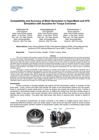
Torque converter is mounted between the engine and the transmission system. It consists of main
three parts – pump, turbine and stator that transfer the power to the transmission system from the engine.
Pump is connected to engine shaft which is driven by engine and imparts the energy to fluid. Turbine is
connected to transmission system through gear box. It intakes the energy from fluid and transfer power to
wheels. Stator is key part in the torque converter which diverts the oil flow from turbine to pump without
affecting the pump rotation. This gives high stall torque ratio which is required when vehicle is started to
move.
The important characteristic of torque converter is the ability to multiply torque when there is
substantial difference between input and output speed. It also serves as automatic clutch to transmit power
and avoiding the engine vibration transfer to transmission system that results in smoothened output power
and driving comfort.
Figure 1: Torque Converter
Simulation Driven Innovation 1
2. Process Methodology
Torque Converter cad model generated in CATIA
Case 1 Case 2
Meshing in HyperMesh Meshing in
AcuConsole
Solution by FVM Solver Solution with Altair
AcuSolve (FEM)
Validation of results
Validation of results
Checking the feasibility for automation of TC Hydraulic Performance Simulation
Figure 2: Process Methodology
Formulae Used
Torque converter consists of 30 blades of stator, impeller and turbine. So 12 degree rotational
periodic model is taken for the analysis
݁ݑݍݎܶ ݎ݈݈݁݁݉ܫൌ ݎݐܿܽܨ ݊݅ݐ݈ܽܿ݅݅ݐ݈ݑܯൈ ݁ݑݍݎܶ ݎ݈݈݁݁݉ܫሺ12 degሻ…………. (1)
ܶ ݁ݑݍݎܶ ܾ݁݊݅ݎݑൌ ݎݐܿܽܨ ݊݅ݐ݈ܽܿ݅݅ݐ݈ݑܯൈ ܶ݁ݑݍݎܶ ܾ݁݊݅ݎݑሺ12degሻ……………. (2)
Where,
Multiplication factor=30
்௨ ௌௗ
ܵ ݅ݐܽݎ ݀݁݁ൌ ….............................................................................................. (3)
ூ ௌௗ
்௨ ்௨
ܶ ݅ݐܽݎ ݁ݑݍݎൌ ……………………………………………………………………. (4)
ூ ்௨
ூ ௌௗ
ܭെ ݎݐܿܽܨൌ …………………………………………………………… (5)
ඥூ ்௨ ି௧
Quality criteria used for Meshing
Torque converter contains four fluid regions such as impeller, turbine, lockup and stator. This fluid model is meshed
with tetrahedral elements. As per the quality requirement, maximum element size is assigned as 1 mm. Skewness for
the surface mesh is kept less than 0.7 and sqewness for the volume mesh is maintained less than 0.9. The most
important part in torque converter is Stator, because it directs the flow from turbine to impeller. So it is necessary to
capture all the features in stator with refined mesh. For that purpose, Proximity and Curvature size function is applied
to Stator fluid. As it is a periodic model, same type of mesh is generated on both periodic faces.
Simulation Driven Innovation 2
3. Case1: Meshing in HyperMesh
Impeller blades Turbine blades Stator blade-Curvature
and proximity
In the first case, Surface mesh and Volume mesh
is generated in HyperMesh. Skewness for Surface mesh is
less than 0.7 and Skewness for Volume mesh is less than
0.9
Challenges
• Meshing cannot be fully automated by using
Batch Mesher
Figure 3: Meshing in Hyper Mesh
Impeller Stator Turbine Lockup
Simulation Driven Innovation 3
4. Results & Discussions
Solution with FVM solver:
The HyperMesh fluid model is solved using FVM solver. Steady state solver with incompressible
turbulent flow settings is selected. Coupled algorithm for pressure-velocity coupling is used. As it is turbo
machinery simulation, Moving Reference Frame (MRF) approach is applied for pump and turbine regions.
The MRF approach implies that there is no relative mesh motion of the rotating and stationary parts. By
using right hand thumb rule, rotation direction for lockup, impeller and turbine is defined. Well established
Realizable K- אTurbulence model (2 eqn) is selected for capturing turbulence and oil properties are
assigned. Impeller rotates at engine speed and turbine speed is assigned based on the speed ratio. To
improve the calculation stability, initially calculation is performed with first order upwind scheme then it is
switched to second order upwind scheme
Results Comparison By comparing the results, there is
Spee Test results HYPERMESH Difference(%) maximum 6.29% in K-Factor and
d Torque Torque Torque 3.33% in Torque ratio deviation
ratio K-Factor ratio K-Factor
ratio
K-Factor between HyperMesh results and
ratio
Test results.
0 257.5 1.93 242.3 1.87 6.29 2.92 HyperMesh is satisfying
0.1 249.6 1.82 239.9 1.76 4.06 3.33 the quality criteria that we are
0.2 243.0 1.68 234.2 1.68 3.74 0.39 following and well aligned with our
0.3 234.2 1.59 228.4 1.56 2.53 1.52 process.
0.4 226.9 1.47 223.2 1.47 1.69 0.28
0.5 218.7 1.34 216.1 1.32 1.20 1.16
0.6 206.9 1.22 205.0 1.22 0.93 0.49
0.7 203.8 1.13 197.1 1.12 3.39 0.57
0.8 213.8 1.03 211.5 1.01 1.10 2.15
0.85 223.7 1.01 216.7 0.99 3.25 1.71
0.9 267.2 1.03 219.8 0.94 21.59 9.25
Table 1: Comparison of Test results and HyperMesh results
300.0 2.50
Comparison of K-Factor Comparison of Torque Ratio
250.0 Test
2.00
HyperMesh
Test
HyperMesh
200.0
K-Factor
1.50
Torque Ratio
150.0
1.00
100.0
0.50
50.0
0.0
0 0.1 0.2 0.3 0.4 0.5 0.6 0.7 0.8 0.85 0.9 0.00
Speed Ratio 0 0.1 0.2 0.3 0.4 0.5 0.6 0.7 0.8 0.85 0.9
Speed Ratio
Figure 4: Comparison of HyperMesh results with Test results
Simulation Driven Innovation 4
5. Case 2: Meshing in AcuConsole
Figure 5: Meshing in AcuConsole Periodic Boundary faces
In the Second case, mesh is generated in
AcuConsole. The fluid model is meshed with
tetrahedral elements. As per the quality
requirement, maximum element size is assigned
as 1 mm. In periodic boundary condition each
element is paired with other opposite element.
The visualization of periodic elements is easily
understandable
Challenges
• To create periodic mesh, coordinate
values are needed. But finding coordinate
values in AcuConsole is difficult
• There is no geometry cleanup and mesh
editing features
Simulation Driven Innovation 5
6. Results & Discussions
Solution with Altair AcuSolve (FEM) solver:
Altair AcuSolve is an FEM solver used for this TC hydraulic performance simulation. Moving
Reference Frame (MRF) and Spallart Allmaras (one eqn) Turbulence model is used. And other boundary
conditions are same for both cases. The result obtained from AcuSolve is second order. It produces the
faster convergence results
Results Comparison
By comparing the
Test results Altair AcuSolve Difference(%) results, there is maximum 11.52
Speed % in K-Factor and 16.62 % in
ratio K-Factor Torque Torque Torque
K-Factor K-Factor Torque ratio deviation between
ratio ratio ratio AcuSolve results and Test
0 257.5 1.93 230.9 1.68 11.52 14.66 results.
0.1 249.6 1.82 225.2 1.56 10.86 16.62
0.2 243.0 1.68 227.3 1.55 6.89 8.48
0.3 234.2 1.59 220.8 1.43 6.03 10.70
0.4 226.9 1.47 216.7 1.27 4.74 15.92
0.5 218.7 1.34 207.4 1.13 5.46 17.97
0.6 206.9 1.22 198.0 1.09 4.49 12.35
0.7 203.8 1.13 196.8 0.96 3.57 18.04
0.8 213.8 1.03 207.4 0.87 3.09 18.81
0.85 223.7 1.01 211.5 0.87 5.76 16.89
0.9 267.2 1.03 216.7 0.70 23.33 46.07
Table 2: Comparison of Test and Altair AcuSolve results
300 2.5
Comparison of K-Factor Comparison of Torque ratio
Test
250 Test
FEM-AcuSolve 2.0
FEM-AcuSolve
200
1.5
Torque ratio
150
K-Factor
1.0
100
0.5
50
0 0.0
0.00 0.10 0.20 0.30 0.40 0.50 0.60 0.70 0.80 0.85 0.90
0.00 0.10 0.20 0.30 0.40 0.50 0.60 0.70 0.80 0.85 0.90
Speed ratio Speed ratio
Figure 6: Comparison of Test and Altair AcuSolve results
Simulation Driven Innovation 6
7. Benefits Summary
HyperMesh is the promising software for our TC hydraulic performance simulation. It is reducing the
preprocessing hours considerably when CFD model is bigger than 12 deg.
In other end, AcuSolve has inbuilt preprocessor and has single GUI for meshing and solving. It
avoids mesh export from preprocessor and import to solver time. And it eliminates clean-up and mesh
quality improving time.
Challenges
Initially we faced periodic definition issue for our fluid model in AcuSolve. For post processing the
contours and vectors, we need to use HyperView separately. If it is inbuilt in AcuSolve, then it will be more
convenient. AcuSolve help documentation is not in detail about features and improvement is needed.
Future Plans
We are planning to validate further HyperMesh for our TC simulation meshing automation. Also we
are planning to validate AcuSolve for other periodic angles like 36 deg, 120 deg and full model simulation to
understand the results variations & correlation with test measurement.
Conclusions
We are looking for complete automation for TC hydraulic performance simulation. So we are
validating AcuSolve competency for our process. It shows that AcuSolve can be confidently used to
compare two or more designs for identifying better design quickly. However, difference between AcuSolve
and test measurement is slightly larger than our current process software. We hope it will be improved by
appropriate solver settings and in future release versions.
ACKNOWLEDGEMENTS
The authors would like to thank Altair Engineering, India for providing technical support in Altair
AcuSolve. The authors would also like to thank Mr.Sriram, R&D Director and Bagath Singh R, engineering
Manager, Power Train Transmissions, VIPL, Chennai for their constant encouragement
REFERRENCES
[1] Versteeq H.K. and W. Malalasekara “An Introduction to Computational Fluid Dynamics”, Longman Group Ltd, 1995.
[2] Ubaldi M., Zunino P., Barigozzi G. and Cattanei A., "An Experimental Investigation of Stator Induced Unsteadiness on
Centrifugal Impeller Outflow", Journal of Turbo machinery, vol.118, 41-54, 1996.
[3] Ramamurthi, V., “Finite Element Method in Machine Design”, Narosa Publishing House, January 2009,
ISBN: 978-81-7319-965-3
[4] Combès, J.F., Bert, P.F. and Kueny, J.L., "Numerical Investigation of the Rotor-Stator Interaction in a Centrifugal
Pump Using a Finite Element Method", Proceedings of the 1997 ASME Fluids Engineering Division Summer Meeting,
FEDSM97-3454, 1997.
Simulation Driven Innovation 7