
Recommandé
Contenu connexe
Tendances
Tendances (20)
En vedette
En vedette (20)
Similaire à Gsm anti theft system
Similaire à Gsm anti theft system (20)
Plus de Ashu0711
Plus de Ashu0711 (20)
Gsm anti theft system
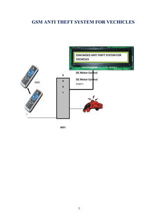
- 1. GSM ANTI THEFT SYSTEM FOR VECHICLES GSM BASED ANTI THEFT SYSTEM FOR VECHICLES DSF DC Motor Control 8 DC Motor Control 0 SMS PORT1 5 1 8051 1
- 2. TABLE OF CONTENTS 1.1 Introduction 1.2 Methodology 1.3 Scope of Work 1.4 Aims of the GSM ANTI THEFT SYSTEM FOR VECHICLES 1.5 Objectives of the GSM ANTI THEFT SYSTEM FOR VECHICLES 2.0 Theoretical Background 2.1 GSM Architecture 2.2 GSM Frequencies 2.3 Network Structure 2.4 Subscriber Identity Module (SIM) 2.5 Literature Review 2.6 GSM Security 2.7 Circuit Diagram of the GSM ANTI THEFT SYSTEM FOR VECHICLES 3.1 GSM Modem 3.1.1 Accessing GSM MODEM using Microsoft HyperTerminal 3.2 Testing of GSM Modem 3.3 List of Important AT Commands 3.4 Microcontroller – MODEM Interfacing 3.4.1. DTE and DCE 3.4.2. RS-232 2
- 3. 3.4.3. RTS/CTS Handshaking 3.4.4. Specifying Baud Rate, Parity & Stop bits 3.4.5 DCE Baud Rates 4.1 Initializations 4.1.1 Serial transfer using TI and RI flags 4.1.2 Validity Check 4.1.3 Display 4.2 Components List 5.1 Conclusion 5.2 Problems Encountered 5.3 Future Improvement 3
- 4. 1.1 Introduction: In the present growing economy of India, the country also faces the uprising of crime Rate. The offense has generated losses in properties, valuables and money and many Solutions are performed to minimize and to prevent the crime. Vehicles theft, which is the main concern for the conduct of this project, is one of the biggest crimes which are hard to eliminate. The latest trend of Vehicles Theft involves the vehicles being towed away, and also alarm signal capturing where the alarm disabler signal can be traced and duplicate by a thief with the device to capture the signal and use it to disable the alarm. There are many alternatives to prevent the vehicles theft, common vehicles alarm system which nearly all cars have the system installed, and also Global Positioning System (GPS) where the whereabouts of the vehicle scan be traced. Other alternatives include steering and gear lock, tire lock, hidden “kill” switches which incapacitate fuel flow and many others. The project and research is conducted for additional features in vehicles alarm system. The device can be added to the present vehicles alarm system without any major modification to it. When the vehicles alarm is triggered, through forced entry or motion sensor detection, the in-vehicles phone will send SMS message to the owner’s mobile phone to alert him or her to check the vehicle. Usually, vehicles owner realizes that their vehicles has been stolen long after the incident, which the vehicles thief probably gotten away, and disables all the security features in the car, or cannibalized the vehicles for spare parts and expensive items. This happens when the owner is far away from the vehicle to hear the alarm. The SMS message gives immediate alert to the vehicles owner, even if the thief gotten away with the car, so that the owner can immediately take instant actions to notify the local police department or contact the vehicles immobilizer service which come with most GPS car system to immobilize the vehicle. The main components of the toolkit include microcontroller, GSM modem. These components are integrated with the device board and thus incorporate the wireless features. The GSM modem sends the SMS. The AT commands are serially transferred to the modem. In return the modem transmits the stored message through the wireless link. The microcontroller used in this case is ATMEL AT89S52 .Motorola W220 is used as the GSM modem. In this prototype model, LCD display is used for simulation purpose. The results presented in the thesis support the proper functionalities and working of the system. The timing diagram suggests the response of the modem to various AT (attention) commands. 4
- 5. 1.2 Methodology: The method used to carry out this project is the principle of serial communication in collaboration with embedded systems. This is a very good project for Industries. This project has a GSM ANTI THEFT SYSTEM FOR VECHICLES, which will be used as the electronic device, and also a GSM modem, which is the latest technology used for communication between the mobile and the embedded devices. System will work like when the user wants to send a sms on the mishaps like someone try to open the door of the vehicles, gas leakage at your houses and offices; the modem sent a message through the subscriber identity module (SIM) which is inserted in the display system MODEM. 1.3 Scope of Work I will use liquid crystal display for displaying the message; I will also use GSM modem (Motorola W220) as an interface between mobile and microcontroller. It will send message to any phone irrespective of the GSM network through the modem connected to the programmable device. 1.4 Aims of the GSM ANTI THEFT SYSTEM FOR VECHICLES 5
- 6. Uses: This is very useful and innovative project. We can use this to secure our offices and houses to save our property from mishaps. 1.5 Objectives of the ANTI THEFT SYSTEM FOR VECHICLES Programming of the mobile phone with AT (Attention) command sequence Interfacing the programming chip with the personal computer Interfacing the programmable chip with the Buzzer and Sensors. Interfacing of the mobile phone with the programmable chip Sending messages from the remote phone to control device. 2.0 Theoretical Background GSM (Global System for Mobile communications: originally from GROUPE Special Mobile) is the most popular standard for mobile phones in the world. Its promoter, the GSM Association, estimates that 80% of the global mobile market uses the standard. GSM is used by over 3 billion people across more than 212 countries and territories . Its ubiquity makes international roaming very common between mobile phone operators enabling subscribers to use their phones in many parts of the world. GSM differs from its predecessors in that both 6
- 7. signaling and speech channels are digital, and thus is considered a second generation (2G) mobile phone system . This has also meant that data communication was easy to build into the system. 2.1 GSM Architecture: GSM is a complex system and difficult to understand. The Mobile Station (MS) refers to the mobile equipment . The Base Station Subsystem controls the radio link with the Mobile Station. The Network Subsystem performs main functions such as switching of calls between mobile users, mobility management operations, and proper operation and setup of a network . These functions are controlled by the Mobile Services Switching Center (MSC). 2.4 GSM Frequencies: GSM networks operate in a number of different frequency ranges (separated into GSM frequency ranges for 2G and UMTS frequency bands for 3G). Most 2G GSM networks operate in the 900 MHz or 1800 MHz bands. Some countries in the Americas (including Canada and the United States) use the 850 MHz and 1900 MHz bands because the 900 and 1800 MHz frequency bands were already allocated. Most 3G GSM networks in Europe operate in the 2100 MHz frequency band . 2.5 Network Structure: The network behind the GSM seen by the customer is large and complicated in order to provide all of the services which are required. 7
- 8. • The Base Station Subsystem (the base stations and their controllers). • The Network and Switching Subsystem (the part of the network most similar to a fixed network). This is sometimes also just called the core network. • The GPRS Core Network (the optional part which allows packet based Internet connections). • All of the elements in the system combine to produce many GSM services such as voice calls and SMS. 2.6 Subscriber Identity Module (SIM): One of the key features of GSM is the Subscriber Identity Module, commonly known as a SIM card. The SIM is a detachable smart card containing the user's subscription information and phone book. This allows the user to retain his or her information after switching handsets [10]. Alternatively, the user can also change operators while retaining the handset simply by changing the SIM. Some operators will block this by allowing the phone to use only a single SIM, or only a SIM issued by them; this practice is known as SIM locking, and is illegal in some countries . 2.7 Literature Review: This project is an implementation to the idea of the wireless communication between a mobile phone and a microcontroller. Currently the main work that has been done on this proposed system is through serial port to the computer but not wireless. If they want to 8
- 9. control the ANTI THEFT SYSTEM FOR VECHICLES design, the systems need not be reprogrammed to control ANTI THEFT SYSTEM FOR VECHICLES changing the programming of microcontroller. The device will send SMS to the owner mobile number, if the security of the vehicle in danger. 2.8 GSM Security: GSM was designed with a moderate level of security. The system was designed to authenticate the subscriber using a pre-shared key and challenge-response. Communications between the subscriber and the base station can be encrypted. 9
- 10. Fig. 2.2 Block Diagram As we see in the above figure, there are at least three interfacing circuits, MAX-232 with Microcontroller, LCD display with microcontroller, and MAX-232 with GSM MODEM. 2.9 Circuit Diagram of the GSM ANTI THEFT SYSTEM FOR VECHICLES: 10
- 11. POWER SUPPLY: Power supply is a reference to a source of electrical power. A device or system that supplies electrical or other types of energy to an output load or group of loads is called a 11
- 12. power supply unit or PSU. The term is most commonly applied to electrical energy supplies, less often to mechanical ones, and rarely to others. Here in our application we need a 5v DC power supply for all electronics involved in the project. This requires step down transformer, rectifier, voltage regulator, and filter circuit for generation of 5v DC power. Here a brief description of all the components is given as follows: TRANSFORMER: A transformer is a device that transfers electrical energy from one circuit to another through inductively coupled conductors — the transformer's coils or "windings". Except for air-core transformers, the conductors are commonly wound around a single iron-rich core, or around separate but magnetically-coupled cores. A varying current in the first or "primary" winding creates a varying magnetic field in the core (or cores) of the transformer. This varying magnetic field induces a varying electromotive force (EMF) or "voltage" in the "secondary" winding. This effect is called mutual induction. If a load is connected to the secondary circuit, electric charge will flow in the secondary winding of the transformer and transfer energy from the primary circuit to the load connected in the secondary circuit. The secondary induced voltage VS, of an ideal transformer, is scaled from the primary VP by a factor equal to the ratio of the number of turns of wire in their respective windings: By appropriate selection of the numbers of turns, a transformer thus allows an alternating voltage to be stepped up — by making NS more than NP — or stepped down, by making it. 12
- 13. BASIC PARTS OF A TRANSFORMER: In its most basic form a transformer consists of: • A primary coil or winding. • A secondary coil or winding. • A core that supports the coils or windings. Refer to the transformer circuit in figure as you read the following explanation: The primary winding is connected to a 60-hertz ac voltage source. The magnetic field (flux) builds up (expands) and collapses (contracts) about the primary winding. The expanding and contracting magnetic field around the primary winding cuts the secondary winding and induces an alternating voltage into the winding. This voltage causes alternating current to flow through the load. The voltage may be stepped up or down depending on the design of the primary and secondary windings. = REGULATOR IC (78XX): It is a three pin IC used as a voltage regulator. It converts unregulated DC current into regulated DC current. 13