Ship failure
•
4 j'aime•5,434 vues

The document discusses various ship failures caused by welding defects. It provides examples of ship failures from the early 20th century to modern times, caused by issues like brittle steel, poor welds, corrosion and fatigue cracks originating from welds. The types of welding defects discussed include lack of penetration, porosity and cracking. The document emphasizes the importance of thorough inspection and material testing to understand the root causes of failures in welded ship structures.

Recommandé
Contenu connexe
Tendances
Tendances (20)
En vedette
Similaire à Ship failure
Similaire à Ship failure (20)
Dernier
Dernier (20)
Ship failure
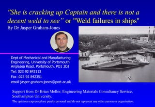
- 1. "She is cracking up Captain and there is not a decent weld to see” or "Weld failures in ships" By Dr Jasper Graham-Jones Dept of Mechanical and Manufacturing Engineering, University of Portsmouth Anglesea Road, Portsmouth, PO1 3DJ Tel: 023 92 842113 Fax :023 92 842351 email jasper.graham-jones@port.ac.uk Support from Dr Brian Mellor, Engineering Materials Consultancy Service, Southampton University. The opinions expressed are purely personal and do not represent any other person or organisation.
- 2. Ship Failure & Loss of Life •Titanic (14 April 1912) Weak rivets and Brittle steel hull. x 1930’s Welded ships, Manual Metal Arc x Liberty Ship failures. WW2 +250 ships fractured or cracked; 19 of these broke completely in two. x Fracture Mechanics comes of age! x Factors:- stress concentration, high tensile stress, relatively low temperature, susceptible steel
- 3. Esso Manhattan 29 March 1943 at the entrance to New York Harbour John P. Gaines, November 1943. Vessel broke in two off Shumagin Aleutians With the loss of ten lives
- 4. Schenectady, A liberty Tanker, 16 January 1943, split in two while moored in calm water. Only 24 hrs old
- 5. Post-War Ship Failures x Tyne Bridge, Kow loon Bridge, Longitudinal beam cut and weld either side of the bulk head frame 65. Poor welding design, laminar tearing, fractures, etc? x Derbyshire 9/10 Sept 1980, associated with poor structural strength, and poor design of hatch covers. (doubled skinned) x Torrey Canyon, Ran aground (19th March 1967) x Costly £ Billions: insurance and life expectancy x Many Lives, Environmental Damage: who is affected?
- 6. Welding Methods x Manual Metal Arc (Most common in ship building) x MIG (Easy to use, but not as portable) x TIG (Mix of above, but harder) x Submerged metal arc. x Gas welding x Solid phase bonding (explosive welding, Friction Stir) x Electron beam & Laser Welding
- 7. Welding Defects x Solidification cracking x Lack of fusion x Lack of penetration x Porosity (Hydrogen) x Distortion x Fatigue, Corrosion, Embrittlement, etc….
- 8. Welded Joints & Defects Butt Joint Lap Joint Tee, joint Corner Joint Edge weld Fillet and Full Penetration
- 10. Tanker 1 Failure x Force 8 gale in the Indian Ocean, land 800 mile. x Noise & vibration at the bow x Witness:- Irish deckhand, Mast Lights •Bow disappears??? •What would YOU do next? •Sailed 1200 miles in reverse to destination in India.
- 11. No.1
- 12. No.2
- 17. 1 2 Photo 37, Side longitudinal 27 Cracked through (1) Fatigue crack at toe of Bracket (2)Longitudinal detached (cracked or never connected?)
- 18. Photo 38 Bracket at side longitudinal 29, Note renewed bracket is smaller than original. Remains of original bracket are visible
- 19. Not renewed and L26 fractured at weld
- 20. Highly corroded non-renewed longitudinal (see photo 46)
- 21. What happen? x Many experts sent to photograph and assess ship. x Design change to a fuel efficient engine thus no bow fuel tank installed. x Fuel tank considered as a stressed member. x Corrosion Fatigue, cracks originating from the welds on one side. Rapid crack growth, considerable distortion, and final fracture on far side.
- 22. Tanker Failure 2 x Background, Super tanker 250,000 Tonnes, 20,000 T water ballast, Oil cargo just unloaded. x Greek owners, Japanese built, USA standards, British Insurer (Lloyds), repaired in Singapore. x Failed in Amsterdam, Holland at Shell Oil terminal. Loud bang and ship moved and strained on it’s ropes from the quay side.
- 23. Ship Failures 30 metre Fracture in 25-30mm Steel plate
- 24. Failure x Initial unexpected soft grounding x Loud bang, and ship movement caused by 20kT of water. x Dry dock: 30m (90ft) crack through 25-30 mm thick steel plate. x Many internal weld failures and buckled steel members. x Repair cost £10 million, not including loss of trade
- 26. What happened? x 30m brittle fracture, then escaping ballast water causes bent steel sections and failed welds. x Material of poor quality. (low temperature brittleness, sulfide inclusions) x Weld failures, Examine Standards, for general ships. Fillet or Fully Penetrating welds
- 27. Fracture in bottom plating of oil tanker 18 m fracture in 25 mm thick bottom plating.
- 30. Inside the centre ballast tank Port transverse web frames.
- 32. Initial examination of ship. x Design specified fully penetration welds. x Although corrosion within standard (25% thickness). x Many welds pulled out, many crack originate from welds. x Fillet welds not as strong, but easier and quicker to do compared to fully penetrating. x Ship has fillet welds????
- 34. Selection of samples for laboratory examination
- 36. Setup Metallurgical Inspection x Visit site, cut out 3/4 Tonne of samples. x Take before and after photos, detail exact locations and record on samples. Securely pack in box for shipping x Set up lab, dry storage, logging samples, photographs, agree samples with all parties. x Layout in lab and agree which smaller samples to cut from the main samples. Concentrated on fracture path. Agree cutting method as some methods can damage samples. (Make sure samples are not cleaned)
- 37. Laboratory investigation Underside of face plate on transverse web just above diagonal stiffener. Transverse section at S. 16 mm gap between transverse web and face plate has been “filled” with weld metal.
- 38. Laboratory investigation continued Transverse section through diagonal stiffener and upper and lower sections of transverse web.
- 39. Results x Lack of penetration and fusion x Mix of old and new repair welds x Considerable weld build up to conceal poor fit up. x Some cracked welds not repaired (old fatigue marks) and painted over (paint deep inside cracks). x Although outside profile good, large pores at weld centre.
- 40. Weld details x Poor fit up “cured” by filling gap with weld metal. x Misalignment of upper and lower sections of transverse web. x True weld leg lengths as small as 2 mm. Corrosion reduced effective weld throat size.
- 41. Weld details continued x Weld between upper and lower sections of transverse web should be a butt weld not a fillet weld. x This had no effect on the static strength of the joint but the fatigue strength of a butt weld is 1.6 times that of a well prepared fillet weld.
- 42. Welded structures fracture along welds so FE models Welds and structural failure must replicate this.
- 43. Use sub-models of weld details Load elongation on 5 mm element corresponding to fillet weld leg length. Input into main FE model. Pull off failure of fillet welded bracket.
- 44. Local Materials Properties •Modelling of complex failure sequences in welded structures using FE is hampered by lack of local material properties. •Use an instrumented microhardness technique with a spherical indenter to derive the stress-strain curve for local regions of a weld.
- 45. Conclusions continued x The failure mode is only part of the story. x Need to answer question, “What is special about this part?”.
- 46. Tanker 2 failure conclusions x Poor build and repair, (likely known to owner??) x Uneven loading with full ballast tanks. x Soft mud grounding. (Owners requested non-grounding berth) x Ship unable to support own weight and that of ballast. x Longitudinal split allowing water to rush out (10KT/min) causing further damage. x Some damage possible from dry dock.
- 47. Inspection, What happened? x One man (US) to inspect a 250,000 t Tanker, built in Japan. Language problem? x Ship access, individual weld inspection problems? Poor inspection in difficult conditions. x Why can’t ships be inspected like planes???? x MONEY (Cost to benefit)
- 48. Overview x Ship losses are primarily caused by a number of events, perhaps even minor when considered individually in isolation, which conspire together in a sequence which leads inevitably to the loss x Failures will occur, and are required to be managed (Failure Management) x There will be the inevitable differences of opinion depending upon particular points of view and interest. x You have to strive throughout to treat all possible scenarios equally in terms of effort, time and depth of analysis.
- 49. Areas of Future Research x Structural Design – Modelling & Analysis of loading x Life Cycle Risk Management – Corrosion rates, time variable stresses x Production Technology – Good fit-ups & Production design detail x People Dynamics & concepts of risk assessment. – ’Groupthink’ & ’Risky shift phenomenon'
- 50. Seacat propeller failure. x New in service, Vibration from propeller. x Dry dock, Half a blade missing (1 of 3). x Initial inspection, fatigue and brittle overload failure. x Detailed inspection, small pore, and welding heat affected zones around fatigue initiation sites.
- 51. Cause of propeller failure x Overlay welded to repair a casting problem. x Poor finishing and NDT (Dye penetrate). x Small pore, stress concentration, leading to fatigue initiation. x Crack growth, followed by multiple fatigue initiation sites and rapid crack growth around welds x Possible damage or excessive wear to bearings.
- 52. Metallurgical testing methods x Eye, magnifying glass, (cracks, distortion) x Stereo low powered microscope. Cut samples, polish smooth (stain) and examine for heat affected zones. x High power microscope, Electron beam microscope (Fatigue striations, inclusions, etc).
- 53. Local materials properties Use an instrumented microhardness technique with a spherical indenter to derive the stress-strain curve for local regions of a weld.