Acopladores para armaduras
•
0 likes•1,671 views

O uso de acopladores Ancon simplificara concepção e construção em betão armado e reduz a quantidade de reforço necessário. Os Acopladores Ancon para União de varões de aço nervurado existem em três conceitos: Aperto Lateral - Rosca Cónica - Rosca Direita Apresenta ainda suloções de posicionamento e transição de diâmetros.

Recommended
Recommended
More Related Content
What's hot
What's hot (17)
Similar to Acopladores para armaduras
Similar to Acopladores para armaduras (20)
More from CORTARTEC
More from CORTARTEC (11)
Acopladores para armaduras
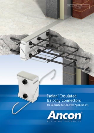
- 1. CI/SfB (23.79) Et6 February 2008 Isolan® Insulated Balcony Connectors for Concrete to Concrete Applications
- 2. 2
- 3. 3 Ancon designs and manufactures high integrity steel products for the construction industry. Through continuous programmes of new product development, inward investment and employee advancement, the company is committed to maintaining the highest level of customer service within a dynamic and challenging industry. Ancon Isolan connectors join external concrete balconies to internal concrete floor slabs. Used to minimise cold bridging, these connectors provide continuity to the thermal insulation in the wall. Standard systems, comprising rigid CFC-free polystyrene insulation and stainless steel shear reinforcement, suit most depths of cantilever and simply supported balconies. Introduction to Ancon Isolan 4 Isolan Systems 5 Applications 6 System Components 7 Specification Guidance 8 Design Examples 9 Isolan MV System 10-12 Isolan V System 13 Isolan FD/FZ Systems 14 Enquiry/Order Form 15 Corner Details 16-17 Reinforcement Anchorage Lengths 17 Installation Guidance 18 Products for Structural Concrete Division 19 Other Ancon Products 19 Masonry Support Systems Masonry Reinforcement Windposts and Lintels Wall Ties and Restraint Fixings Channel and Bolt Fixings Tension Systems Stainless Steel Fabrications Flooring and Formed Sections Shear Load Connectors Reinforcing Bar Couplers Reinforcement Continuity Systems Punching Shear Reinforcement Insulated Balcony Connectors Refractory Fixings ISO 9001: 2000 FM 12226 ISO 14001: 2004 EMS 505377
- 4. 4 Shear Load Connectors Standard Isolan systems, comprising rigid CFC-free polystyrene insulation and stainless steel shear reinforcement, suit most depths of cantilever and simply supported balconies. The various systems allow the transfer of all loads in structural concrete i.e. moment, shear, compression and tension, and are suitable for straight runs and both internal and external corners. System Benefits Ancon Isolan connectors use conventional reinforcing bars to provide the tension and compression reinforcement. When compared to systems where this reinforcement is an integral component, the Ancon Isolan solution can provide substantial cost savings and simplify specification, scheduling, transportation, handling and installation. U-Value The Isolan system has a typical U-value of 0.3 W/m2 K. Curved or Stepped Balconies Special configurations can be manufactured to suit specific project requirements including curved or stepped balconies. Precast Balconies In addition to balconies cast in-situ, Ancon Isolan systems can be used in precast balconies. For such applications, tension and compression bars must be scheduled and installed at the time of casting. Please contact Ancon for more information. ANCON ISOLAN INSULATED CONNECTORS In applications such as balconies, where concrete slabs pass through the building envelope, a cold bridge is created that can result in significant heat loss. The Ancon Isolan system is a structural component used to join external concrete balconies to internal concrete floor slabs. It provides continuity to both the reinforcement and the thermal insulation of the wall protecting the building against the effects of cold bridging. Isolan® Insulated Balcony Connectors 4 Rail ISO-Element Tube Shear Reinforcement ‘PRODUCTS FOR STRUCTURAL CONCRETE’ DIVISION Ancon provides a dedicated service to the concrete sector. The 'Products for Structural Concrete' team advises on the selection of the most appropriate product, provides pricing information and can project manage the supply of all elements to suit the site schedule. Overseas enquiries are also serviced by this team. Our product offering includes, but is not restricted to, balcony connectors, reinforcing bar couplers, reinforcement continuity systems, punching shear reinforcement and shear load connectors. Email concrete@ancon.co.uk, fax +44 (0) 114 238 1240 or call +44 (0) 114 275 5224 with your enquiry. Cold Bridge Ancon Isolan MV System
- 5. Tel: +44 (0) 114 275 5224 Web: www.ancon.co.uk 55 ISOLAN SYSTEMS Standard Isolan systems are available in five heights to suit different depths of balcony i.e. 160, 180, 200, 220 and 240mm, and are supplied complete with stainless steel shear reinforcement. Tension and compression reinforcement to be supplied by others. MV System The Ancon Isolan MV system is used for the transfer of moment and shear forces in cantilevered balconies. FD System The Ancon Isolan FD system is used for the transfer of compression forces. FZ System The Ancon Isolan FZ system is used for the transfer of tensile forces. Special Configurations Isolan components can be individually adapted to suit specific applications. The stainless steel shear reinforcement can be supplied in a range of diameters and bent into other required shapes outside the polystyrene insulation element. The number of tubes can be modified and the standard height of the ISO-Element can be increased. Systems can be manufactured for use in curved or stepped balconies. Please contact Ancon with details of specific applications. V System The Ancon Isolan V system is used for the transfer of shear forces in simply supported balconies. FD FZ Notes: For clarity, main reinforcement (supplied by others) has been omitted from these drawings. The Isolan system should always be orientated so the stainless steel shear reinforcing bars are at the bottom of the slab on the side of the load (the balcony side).
- 6. Ancon Isolan V System with Compression Reinforcement Supplied by Others MV MV MV MV Isolan® Insulated Balcony Connectors 6 APPLICATIONS The Ancon Isolan system is suitable for straight runs and both internal and external corners. The following drawings show example applications in plan view. MV MV MV MV MV MV V V V MV MV MV MV MV MV MV VV Cantilever Balcony Cantilever Balcony at Internal Corner Simply Supported Balcony Supported Slab Recessed Balcony Cantilever Balcony with 90° External Corner Obtuse Angle Corner Cantilever Balcony
- 7. Tel: +44 (0) 114 275 5224 Web: www.ancon.co.uk Tube 7 SYSTEM COMPONENTS ISO-Element The ISO-Element is 60mm thick, CFC-free, rigid white polystyrene insulation in a standard length of 750mm. It is available in five heights (160, 180, 200, 220 and 240mm) to suit different depths of balcony. Shear Reinforcement The shear reinforcement is duplex stainless steel grade 1.4462 and is available in three diameters (6, 8 and 10mm) as standard. In addition to the standard systems, this reinforcement can be bent into other required shapes outside the polystyrene insulation element. Tubes Polypropylene tubes with a 27mm internal diameter are located at pre-determined positions in the ISO-Element to allow for the passage of tension and compression reinforcing bars. Rail A high density polyethylene rail is located on the top edge of the ISO-Element to protect the insulation. Tension/Compression Reinforcement (supplied by others) Reinforcement used for tension and compression bars to be grade 500B to BS4449: 2005 and supplied by others. Fire Protection The Isolan system offers fire resistance to DIN 4102: Fire behaviour of building materials and components. Fire protection can be provided by adding Duripanel fire resistant strips to the base or to the top and base of the ISO-Element. The strips are available in 18, 28 or 36mm thickness providing 30, 60 or 90 minute fire resistance respectively. Examples of how these strips are referenced are 1R30 for a 30 minute strip fixed to the base and 2R90 for a 90 minute strip fixed to the top and base. When specifying and ordering, these references should be added as a suffix to the Isolan system (see page 8), for example 4MV6-200-5Ø12T/ 5Ø16C-1R60. The polyethylene rail is omitted from the ISO Element if these strips are employed to the top. For further information contact Ancon’s Technical Services Team. Height Height Length b Length b Length b d y Shear Bar Shear Bar Shear Bar Angle (mm) (mm) 6mm Dia. 8mm Dia. 10mm Dia. α 160 88 530 670 810 39° 180 108 530 670 810 44° 200 128 530 670 810 47° 220 148 530 670 810 53° 240 168 530 670 810 57° Corrosion Resistance The Ancon Isolan system has been engineered to provide a high resistance to corrosion. The shear reinforcement is stainless steel and the carbon steel tension and compression reinforcement passing through the insulation unit is encased in polypropylene tubes which fill with concrete fines at the time of casting. This prevents water and oxygen from reaching the bars, thus providing corrosion protection. 150mm dy 150mm150mm150mm150mm 82mm 68mm 36mm 36mm dy α Øi = 27mm Shear bar 60mm= b = 750mm Øi = 27mmShear bar Note: Shear bar length (b) tolerance +/-10mm
- 8. SPECIFICATION GUIDANCE Design Information The graphs on pages 10 to 14 are used to select the most appropriate Isolan element, and the diameters of the shear, tension and compression reinforcement. Example calculations are provided on the following page. Consideration should be given to horizontal forces on parapets and local concentrated load checks, these are not included in the examples. The graphs provide the design resistance (ultimate limit state) values for the shear VRd and moment MRd. The Isolan element design is based on normal structural calculations. The calculations are based on the following material properties. Concrete: C25/30 (cylinder/cube compressive strengths) = 30N/mm2 Reinforcement: Shear reinforcement material, duplex stainless bar designation 1.4462 BS6744, Grade 500 Re or Rp0.2 ≥ 500N/mm2 Rm ≥ 550N/mm2 Tension and compression reinforcement, BS4449, Grade 500B Re ≥ 500N/mm2 Rm ≥ 540N/mm2 The partial load factors used in the examples are: Dead load (persistent) = 1.35 Imposed load (quasi) = 1.50 How to Use The Graphs MV Elements 1. The graph for the height of the Isolan element that corresponds to balcony slab thickness is selected. 2. The design shear capacity required (unit: kN per linear metre) is plotted on the horizontal axis of the graph and a vertical line drawn. From this, the relevant Isolan element type (i.e. 2MV6, 4MV6, 4MV8 or 4MV10) is selected. 3. The bending moment capacity required (unit: kNm per linear metre) is plotted on the vertical axis of the graph and a horizontal line drawn. 4. The intersection between the vertical line corresponding to the design shear capacity and the horizontal line corresponding to the design moment capacity determines the respective diameters of the tension and compression reinforcement e.g. Ø12T/Ø16C. The first number refers to tension and the second to compression reinforcement. Refer to the drawings on page 10 for the number of bars required. V Elements 1. The balcony slab thickness is selected on the horizontal axis of the graph and a vertical line drawn. 2. The design shear capacity required (unit: kN per linear metre) is plotted on the vertical axis of the graph and a horizontal line drawn. 3. The intersection between the vertical line corresponding to the balcony slab thickness and the horizontal line corresponding to the design shear capacity determines the Isolan element type and diameter/number of compression bars. FD Elements 1. The concrete thickness is selected on the horizontal axis of the graph and a vertical line drawn. 2. The design compression capacity required (unit: kN per linear metre) is plotted on the vertical axis of the graph and a horizontal line drawn. 3. The intersection between the vertical line corresponding to the concrete thickness and the horizontal line corresponding to the design compression capacity determines the Isolan element type and diameter/number of compression bars. FZ Elements 1. The concrete thickness is selected on the horizontal axis of the graph and a vertical line drawn. 2. The design tensile capacity required (unit: kN per linear metre) is plotted on the vertical axis of the graph and a horizontal line drawn. 3. The intersection between the vertical line corresponding to the concrete thickness and the horizontal line corresponding to the design tensile capacity determines the Isolan element type and diameter/number of tension bars. Calculation Method A hard copy of the calculation to derive the load graphs is available from Ancon on request. Balcony Deflection The deflection of the equivalent ‘monolithic’ balcony should be calculated in the usual way, in compliance with relevant standards and design codes. A coefficient of 1.20 must be applied to the calculated figure to determine the maximum deflection with Isolan connectors. The final figure can be used to determine the amount of pre-camber to apply to the formwork to compensate for the deflection. Ancon Isolan Product Referencing 4MV8 - 200 - 5Ø12T / 5Ø16C Number of System Number and Number and shear bars, height diameter of diameter of System type, tension bars compression bars Diameter of to be supplied to be supplied shear bars by others by others Typical Specification Clause Once the appropriate Isolan system has been selected from the design graphs, the following clause may be adapted for use. Details in italics must be changed to suit the product reference. 4MV8 - 200 - 5Ø12T / 5Ø16C Ancon Isolan MV system 200mm high comprising CFC-free polystyrene insulation, 60mm thick by 750mm long, and four stainless steel grade 1.4462 shear reinforcing bars of 8mm diameter. System requires five 12mm diameter grade 500B tension bars and five 16mm diameter grade 500B compression bars to be supplied by others. Isolan® Insulated Balcony Connectors 8
- 9. Tel: +44 (0) 114 275 5224 Web: www.ancon.co.uk DESIGN EXAMPLES 1. MV Element Depth 180mm Dead load slab gk = 4.5kN/m2 Imposed load qk = 3.0kN/m2 Parapet load Gk = 5.0kN/m qd = (1.35 x 4.5 + 1.50 x 3.0) = 10.6kN/m2 Gd = (1.35 x Gk) = (1.35 x 5.0) = 6.8kN/m MEd = (qd x I1 2 )/2 + (Gd x I2) = 34.1Nm/m VEd = (qd x I1) + Gd = 28.0kN/m From graph for MV180 select 4Ø6 shear bars, Ø12/16 (tension/compression bars). Product reference 4MV6-180-5Ø12T/5Ø16C. 2. MV Element Depth 220mm Dead load slab gk = 5.5kN/m2 Dead load (point) Gk = 35kN Imposed load qk = 3.0kN/m2 qd = (1.35 x 5.5 + 1.50 x 3.0) = 11.9kN/m2 Gd = (1.35 x Gk) = (1.35 x 35) = 47.3kN/m MEd = (qd x I1 2 )/2 + (Gd x I2) = 57.1kNm/m VEd = (qd x I1) + Gd = 68.7kN/m From graph for MV220 select 4Ø8 shear bars, Ø16/20 (tension/compression bars). Product reference 4MV8-220-5Ø16T/5Ø20C. 3. V Element Depth 200mm Dead load slab gk = 5.0kN/m2 Dead load finishes gk = 2.0kN/m2 Imposed load qk = 5.0kN/m2 qd = (1.35 x 7.0 + 1.50 x 5.0) = 17.0kN/m2 VEd = (qd x l1)/2 = 51.0kN/m From V graph select 200mm 4V8/5Ø12C, (4Ø8 shear bars with 5Nr. Ø12 compression bars). Product reference 4V8-200-5Ø12C. 4. FD Element Depth 200mm Dead load wall Gk = 15kN/m Imposed load wall Nk = 160kN/m FDEd = (1.35 x 15.0) + ( 1.50 x 160.0) = 260.3kN/m From graph for FD, 200mm. Product reference FD-200-2x5Ø12C. 5. FZ Element Depth 220mm Dead load wall Gk = 11kN/m Imposed load wall Nk = 200kN/m FZEd = (1.35 x 11.0) + (1.50 x 200.0) = 315kN/m From graph for FZ, 220mm. Product reference FZ-220-2x5Ø10T. 9 1000mm 2000mm l1 l2 gk + qk Gk 200mm 180mm l1 = 2000mm l2 = 1900mm 1800mm 800mm l1 l2 gk + qk 220mm l1 = 1800mm l2 = 800mm Gk 6000mm I1 gk + qk 200mm I1 = 6000mm 200mm 3000mm h = 3000mm Gk Nk h = 2000mm Gk Nk MV System MV System V System FD System FZ System 2000mm 220mm Note: For clarity, not all reinforcement is shown
- 10. Isolan® Insulated Balcony Connectors 10 ISOLAN MV RANGE 2MV6 2 Shear Bars 6mm Diameter - Supplied 5 Tension and 5 Compression Bars - To be supplied by others 4MV6 4 Shear Bars 6mm Diameter - Supplied 5 Tension and 5 Compression Bars - To be supplied by others 4MV8 4 Shear Bars 8mm Diameter - Supplied 5 Tension and 5 Compression Bars - To be supplied by others 4MV10 4 Shear Bars 10mm Diameter - Supplied 5 Tension and 5 Compression Bars - To be supplied by others MomentMRd(kNm/m) Shear VRd (kN/m) Ø10T/Ø10C Ø12T/Ø16C Ø10T/Ø12C Ø10T/Ø16C Ø16T/Ø20C Ø12T/Ø20C 10 0 10 2MV6 4MV6 4MV8 4MV10 20 30 40 50 60 70 80 90 100 110 120 20 30 40 50 60 Isolan MV Element - 160mm Height Note: See guidance and design examples on pages 8 and 9 530mm d d d d 530mm 670mm 810mm
- 11. Tel: +44 (0) 114 275 5224 Web: www.ancon.co.uk 11 MomentMRd (kNm/m) Shear VRd (kN/m) Ø10T/Ø10C Ø12T/Ø16C Ø10T/Ø12C Ø10T/Ø16C Ø16T/Ø20C Ø12T/Ø20C 10 10 2MV6 4MV6 4MV8 4MV10 20 30 40 50 60 70 80 90 100 110 120 130 140 20 30 40 50 60 70 80 Isolan MV Element - 200mm Height MomentMRd(kNm/m) Shear VRd (kN/m) Ø10T/Ø10C Ø12T/Ø16C Ø10T/Ø12C Ø10T/Ø16C Ø16T/Ø20C Ø12T/Ø20C 10 0 0 10 2MV6 4MV6 4MV8 4MV10 20 Design Example 1 30 40 50 60 70 80 90 100 110 120 130 20 30 40 50 60 70 Isolan MV Element - 180mm Height Note: See guidance and design examples on pages 8 and 9 Note: See guidance and design examples on pages 8 and 9
- 12. 12 Isolan® Insulated Balcony ConnectorsMomentMRd (kNm/m) Shear VRd (kN/m) Ø10T/Ø10C Ø12T/Ø16C Ø10T/Ø12C Ø10T/Ø16C Ø16T/Ø20C Ø12T/Ø20C 10 0 10 2MV6 4MV6 4MV8 4MV10 20 30 40 50 60 70 80 90 100 110 120 130 140 150 160 20 30 40 50 60 70 80 90 100 MomentMRd (kNm/m) Isolan MV Element - 240mm Height Isolan MV Element - 220mm Height 10 0 20 30 40 50 60 70 80 90 Shear VRd (kN/m) 10 2MV6 4MV6 4MV8 4MV10 20 30 40 50 60 70 80 90 100 110 120 130 140 150 Ø10T/Ø10C Ø12T/Ø16C Ø10T/Ø12C Ø10T/Ø16C Ø16T/Ø20C Ø12T/Ø20C Note: See guidance and design examples on pages 8 and 9 Note: See guidance and design examples on pages 8 and 9 Design Example 2
- 13. Tel: +44 (0) 114 275 5224 Web: www.ancon.co.uk ShearVRd(kN/m) 13 Concrete Thickness (mm) 160 20.6 kN/m 41.3 kN/m 73.4 kN/m 114.7 kN/m 180 22.8 kN/m 45.6 kN/m 81.0 kN/m 126.5 kN/m 200 24.0 kN/m 48.0 kN/m 85.3 kN/m 133.2 kN/m 220 26.2 kN/m 52.4 kN/m 93.1 kN/m 145.5 kN/m 240 27.5 kN/m 55.0 kN/m 97.8 kN/m 152.8 kN/m 2V6-4Ø10C 4V6-5Ø10C 4V8-5Ø12C 4V10-5Ø16C 20 0 40 60 80 100 120 140 160 Isolan V Element - Sizes 160, 180, 200, 220 and 240mm 4 Shear Bars 10mm Diameter - Supplied 5 Compression Bars - To be supplied by others 2 Shear Bars 6mm Diameter - Supplied 4 Compression Bars - To be supplied by others 4 Shear Bars 6mm Diameter - Supplied 5 Compression Bars - To be supplied by others 4 Shear Bars 8mm Diameter - Supplied 5 Compression Bars - To be supplied by others 530mm d 530mm d 670mm d 810mm d 4V10 4V8 4V6 ISOLAN V RANGE 2V6 Note: See guidance and design examples on pages 8 and 9 Design Example 3
- 14. Isolan® Insulated Balcony Connectors 14 DirectCompressionFDRd (kN/m) Concrete Thickness (mm) Concrete Thickness (mm) 100 0 200 300 400 500 600 700 800 160 180 200 220 240 FD 2x5Ø12C/750mm FD 2x5Ø10C/750mm FD 2x5Ø16C/750mm FZ 2x5Ø12T/750mm FZ 2x5Ø10T/750mm FZ 2x5Ø16T/750mm Isolan FD Element - Compression Reinforcement Sizes 160, 180, 200, 220 and 240mm 229 kN/m 362 kN/m 735 kN/m DirectTensionFZRd (kN/m) 100 0 200 300 400 500 600 700 800 900 1000 1200 1100 160 180 200 220 240 Isolan FZ Element - Tension Reinforcement Sizes 160, 180, 200, 220 and 240mm 455 kN/m 656 kN/m 1166 kN/m Note: See guidance and design examples on pages 8 and 9 Note: See guidance and design examples on pages 8 and 9 Design Example 4 Design Example 5
- 15. Tel: +44 (0) 114 275 5224 Fax: +44 (0) 114 238 1240 15 ANCON ISOLAN ENQUIRY / ORDER FORM Copy, complete and fax to +44 (0) 114 238 1240 Isolan System Slab Depth d (mm) System Type & Length (standard unit length 750mm) 2 MV 6 m MV System V System mm 4 MV 6 m 4 MV 8 m 4 MV 10 m 2 MV 6 m 4 MV 6 m 4 MV 8 m 4 MV 10 m 2 V 6 m 4 V 6 m 4 V 8 m 4 V 10 m 2 V 6 m 4 V 6 m 4 V 8 m 4 V 10 m FD/FZ System Special Configurations Diameter of Shear Reinforcement mm Sketch of intended application Date ❒ Order ❒ Enquiry Company Address Town Post Code Contact Name Tel Fax Email Delivery Date Delivery Address Town Post Code Contact Name Tel Fax Project Name d d d d mm mm mm mm m mm mm m
- 16. Isolan® Insulated Balcony Connectors 16 CORNER DETAILS At balcony corner configurations, if the diameters of the tensile and compressive reinforcement add up to or are greater than 27mm, attention to the local reinforcement detail is required. This is necessary because the inner diameter of the polypropylene tube is 27mm and if the tubes are maintained in the same horizontal plane, the reinforcement would clash. In the main load bearing direction the Isolan element is selected to suit the height of the slab, so that the compression reinforcement which crosses the 60mm insulation cavity will be located in the 1st layer (bottom steel) and the main tensile reinforcement will be located in the 4th layer (top steel). Refer also to Plan View of Cantilever Balcony and Sections. Plan View of Cantilever Balcony and Sections Key to Reinforcement Layers 2 4 4 2 Compression reinforcement - 1st layer Top of cantilever slab Tensile reinforcement - 4th layer 4MV6-200 4MV6-200 4MV6-200 Tensile reinforcement - 3rd layer 4MV6-1604MV6-180 or4MV6-200 1 1 3 3 4th layer 1st layer 3rd layer 2nd layer As previously noted, the corner detail is dependent upon the reinforcement diameters; the size of the Isolan element at corners needs to be selected to avoid local clashing of reinforcement. A typical plan of a corner balcony is shown below, and the Isolan element selected will be 20mm or 40mm smaller in height than that adopted for the general cantilever design. For example, a cantilever balcony requires a structural slab of height 200mm, accordingly an Isolan MV 200 element would be selected, however locally at the external corner an Isolan element MV 160 is selected to avoid clashing of reinforcing bars. The Isolan MV 160 element is made up to the full slab height of 200mm by using 20mm thick polystyrene make-up strips glued to the top and bottom edges. Similar detailing principles will apply to recessed balconies. Compression reinforcement - 2nd layer Notes: 1. Stainless steel shear bars provided with the Isolan system. All other reinforcement to be provided and detailed by others. 2. The above plan is indicative and for the purposes of clarity does not show all reinforcement required. 3. For anchorage lengths refer to table on page 17.
- 17. Tel: +44 (0) 114 275 5224 Web: www.ancon.co.uk 17 REINFORCEMENT ANCHORAGE LENGTHS: MV ELEMENT/V ELEMENT The information noted in the table shown provides the minimum anchorage lengths for the Grade 500B tension and compression reinforcement; Ancon does not supply this reinforcement with the Isolan system, only the stainless steel shear bars are provided. The Grade 500B anchorage reinforcement must be detailed with the general balcony reinforcement and provided by others. The minimum length of the tension anchorage rebar shall be 50D where D is the nominal rebar diameter. The minimum length of the compression anchorage rebar shall be 35D where D is the nominal rebar diameter. The structural slab shall have a minimum concrete strength Class C25/30 (cylinder/cube compressive strengths). Durability considerations may result in the selection of a higher strength class for most UK applications. Section 1-1 Section 2-2 Section 3-3 Section 4-4 60mmB A D C Compression bars Cantilever Slab Tension bars 160 2020 36 200 160 36 200 Tension Bars Compression Bars Rebar Tension Compression Dimension Dimension Dimension Dimension size anchorage anchorage A min. B min. C min. D min. (mm) (mm) (mm) (mm) (mm) (mm) (mm) 10 500 350 1060 500 760 350 12 600 420 1260 600 900 420 16 800 560 1660 800 1180 560 20 1000 700 2060 1000 1460 700 Note: The tension anchorage length is longer than required by BS 8110-1:1997, Table 3.25 Tensile reinforcement in 4th layer Compressible filler and mastic pointing Tensile reinforcement in 3rd layer Make up strip, top and bottom Facing brickwork Load bearing blockwork 20mm Make up strip 20mm Make up strip Stainless steel shear reinforcement aligned in 1st and 4th layers Compression reinforcement in 1st layer Stainless steel shear reinforcement aligned in 2nd and 3rd layers Compression reinforcement in 2nd layer Note: For clarity, shear reinforcement has been omitted from Section 3-3 and Section 4-4 above.
- 18. 18 INSTALLATION Ancon Isolan components are fast and simple to install. These steps are provided as guidance and should be followed in conjunction with the site engineer’s instructions and structural engineer’s reinforcement details. Any polystyrene which is damaged must be replaced or alternatively, where possible, patched with polyurethane foam to maintain the insulation properties. Step 1 The Isolan system should always be orientated so the stainless steel shear reinforcing bars are at the bottom of the slab on the side of the load (the balcony side). The unit is then positioned and secured to the formwork. On-site Storage Care should be taken to avoid damaging any Isolan components prior to installation. Special care should be taken of the polystyrene units. All components should be stored under cover and away from direct sunlight. Special Configurations Load distribution reinforcing bars must be installed at the bends of the shear reinforcement. Balcony - Loaded side Note: For clarity, not all reinforcement is shown. Shear reinforcement positioned at bottom of slab 60mm 1000mm Isolan unit Compression reinforcement (other bars omitted for clarity) 25mm maximum out of alignment over 1000mm Polypropylene tubes Step 2 Insert the compression bars and tension bars, supplied by others, through the polypropylene tubes, and secure them to the main floor slab and balcony reinforcement. The minimum anchor length must be achieved either side of the Isolan system, see page 17 for detailed dimensions. Care should be taken to ensure that any misalignment of the compression bars does not exceed 25mm in 1000mm (1 in 40) as illustrated in the Part Plan View diagram. Step 3 The concrete should preferably be poured adjacent to the Isolan system and simultaneously to either side to avoid any displacement of the polystyrene units. If the concrete is poured on one side only, the second side being at a later date, then the Isolan units must be securely fixed to avoid displacement. Installation is shown for the MV system but is the same for the V system where the tension bars are excluded. Part Plan View Isolan® Insulated Balcony Connectors Misalignment of Compression Bars 1 2
- 19. Tel: +44 (0) 114 275 5224 Web: www.ancon.co.uk 19 Reinforcement Continuity Systems Reinforcement Continuity Systems are an increasingly popular means of maintaining continuity of reinforcement at construction joints in concrete; they eliminate the need to drill shuttering and can simplify formwork design, thereby accelerating the construction process. The Ancon Eazistrip System is CARES approved and is available in both standard units and special configurations. Reinforcing Bar Couplers The use of reinforcing bar couplers can provide significant advantages over lapped joints. Design and construction of the concrete can be simplified and the amount of reinforcement required can be reduced. The joint can also remain unaffected by any loss of cover because the strength of a mechanical splice is independent of the concrete in which it is located. The range includes threaded and mechanically bolted couplers. Shear Load Connectors Ancon DSD Shear Load Connectors are used to transfer shear across expansion and contraction joints in concrete. They are more effective at transferring load and allowing movement to take place than plain dowels, and can be used to eliminate double columns at structural movement joints in buildings. The two-part construction of these connectors ensures alignment, vital where movement is required. The Ancon DSDQ features a rectangular box section to allow lateral movement in addition to longitudinal movement. Punching Shear Reinforcement Used within a slab to provide additional reinforcement around columns, Ancon Shearfix is the ideal solution to the design and construction problems associated with punching shear. The system consists of double-headed studs welded to flat rails, positioned around the column head. The shear load from the slab is transferred through the studs into the column. Channels and Bolts for Fixing to Concrete Cast-in channels are used for fixing masonry support systems to the edges of concrete floors and beams. Channels are available in different sizes ranging from simple self anchoring channels for restraints, to large capacity channels with integral anchors. A selection of channels can also be supplied plain-backed for surface fixing. Stainless steel expansion bolts and resin anchors complete the range. THE ANCON ‘PRODUCTS FOR STRUCTURAL CONCRETE’ DIVISION Ancon operates a dedicated service to clients in the concrete sector. Products include, but are not restricted to, balcony connectors and those shown on this page. The ‘Products for Structural Concrete’ team provides technical advice, pricing information, guidance on product selection and order fulfilment. Enquiries from overseas are also dealt with by the team. Please email concrete@ancon.co.uk, fax +44 (0) 114 238 1240 or call +44 (0) 114 275 5224. ANCON PRODUCTS Stainless Steel Reinforcement Ancon supplies stainless steel plain and ribbed reinforcing bar direct from stock. Grade 304 stainless steel is readily available. Other grades, including high proof strength material, can be obtained on request. Bar is normally available in 6, 8, 10, 12, 16, 20, 25 or 32mm diameter. Other diameters can be obtained on request. Bars are stocked to a maximum length of 6 metres throughout the size range and can be supplied cut to length, bent and threaded to suit requirements. Special Stainless Steel Fabrications Ancon has a wealth of experience in working with different types and grades of stainless steel. Advanced manufacturing facilities enable one-off or volume orders to be fabricated to individual project requirements and to exacting quality standards. Considerable material stocks are maintained in order to meet urgent delivery deadlines.
- 20. © Ancon Building Products 2008 The construction applications and details provided in this literature are indicative only. In every case, project working details should be entrusted to appropriately qualified and experienced persons. Whilst every care has been exercised in the preparation of this document to ensure that any advice, recommendations or information is accurate, no liability or responsibility of any kind is accepted in respect of Ancon Building Products. With a policy of continuous product development Ancon Building Products reserves the right to modify product design and specification without due notice. These products are available from: Ancon Building Products President Way, President Park Sheffield S4 7UR United Kingdom Tel: +44 (0) 114 275 5224 Fax: +44 (0) 114 276 8543 Email: info@ancon.co.uk Visit: www.ancon.co.uk Ancon (Middle East) FZE PO Box 17225 Jebel Ali Dubai United Arab Emirates Tel: +971 (0) 4 883 4346 Fax: +971 (0) 4 883 4347 Email: info@ancon.ae Visit: www.ancon.ae Ancon Building Products 114 Kurrajong Avenue Mount Druitt Sydney NSW 2770 Australia Tel: +61 (0) 2 8808 1111 Fax: +61 (0) 2 9675 3390 Email: info@ancon.com.au Visit: www.ancon.com.au Ancon (Schweiz) AG Gewerbezone Widalmi 10 3216 Ried bei Kerzers Switzerland Tel: +41 (0) 31 750 3030 Fax: +41 (0) 31 750 3033 Email: info@ancon.ch Visit: www.ancon.ch Ancon Building Products GesmbH Gerspergasse 9/3 Top 1 A-1210 Vienna Austria Tel: +43 (0) 1 259 58 62-0 Fax: +43 (0) 1 259 58 62-40 Email: info@ancon.at Visit: www.ancon.at Ancon GmbH Bartholomäusstrasse 26 90489 Nuremberg Germany Tel: +49 (0) 911 955 1234 0 Fax: +49 (0) 911 955 1234 9 Email: info@anconbp.de Visit: www.anconbp.de ISO 9001: 2000 FM 12226 ISO 14001: 2004 EMS 505377