
Recommandé
Contenu connexe
Tendances
Tendances (20)
Similaire à C2VSim Workshop 4 - C2VSim Groundwater Representation
Similaire à C2VSim Workshop 4 - C2VSim Groundwater Representation (20)
Dernier
Dernier (20)
C2VSim Workshop 4 - C2VSim Groundwater Representation
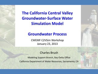
- 1. The California Central Valley Groundwater-Surface Water Simulation Model Groundwater Process CWEMF C2VSim Workshop January 23, 2013 Charles Brush Modeling Support Branch, Bay-Delta Office California Department of Water Resources, Sacramento, CA
- 2. Outline IWFM Groundwater Process Groundwater Budget Z-Budget C2VSim Results
- 4. IWFM
- 6. IWFM Groundwater Process Inflows: Deep Percolation Surface Water Storage
- 7. IWFM Groundwater Process Inflows: Outflows: Deep Percolation Pumping = Surface Water Surface Water Storage Storage
- 8. IWFM Groundwater Process • Simulate a combination of confined, unconfined, and leaky aquifer layers separated by aquitards or aquicludes • Simulate changing aquifer conditions and subsidence • Employ a quasi 3-D approach • Use the Galerkin finite element method for the numerical solution of the governing equation
- 9. IWFM Groundwater Process Simulate the aquifer as unconfined, leaky and confined aquifers separated by aquitards or aquicludes
- 10. Stratigraphy ‘Hangs’ from Ground Surface 250 ft 60 ft -20 ft -280 ft
- 11. Groundwater Flow Equation ∂Ssh − ∇ ( T ∇h) + IuLu (h − hu ) + IdLd (h − hd ) − Q = 0 ∂t Ss = Storativity, (dimensionless); h = Groundwater head, (L); T = Transmissivity = Kh, (L2/T); K = Hydraulic conductivity; (L/T); hs = Saturated thickness of aquifer, (L); t = Time (T); Iu,Id = Indicator functions for top and bottom aquifer, (dimensionless); hu,hd = Groundwater head at adjacent upper and lower aquifer layers, (L/T); Lu,Ld = Leakage coefficients of adjacent upper and lower aquifer layers, (1/T); Q = Source/sink term, (L/T).
- 14. Hydraulic Conductivity Layer 1 Layer 2
- 15. Storage Parameters Layer 1 Layer 2
- 16. Faults – Battle Creek Fault – Red Bluff Arch – Plainfield Ridge Anticline – Pittsburgh – Kirby Hills – Vaca Fault – Vernalis Fault – Graveley Ford Faults – Visalia Fault – Pond-Poso Creek Fault – Edison Fault – White Wolf Fault
- 17. Flow Barrier Parameters Red Bluff Arch
- 18. Unsaturated Zone • Vertical water flow between root zone and water table – In: Deep Percolation – Out: Net Deep Percolation • Divide into two layers of equal thickness
- 20. Groundwater Boundary Conditions x Specified head x Specified flow x General head boundary conditions • Small stream watersheds as dynamically computed flow boundary conditions
- 21. Pumping Pumping by well – Used when exact location and construction details of wells are known – Pumping at the well is distributed to aquifer layers based on the screened interval of the well in an aquifer layer – Well locations described in Preprocessor Well Data File – Well information specified in Pumping Specification File
- 22. Pumping Specification Urban Groundwater Pumping
- 23. Pumping Pumping by element – Used when detailed well information is not available, but pumping amounts for an area that is represented by multiple finite element cells are known – Pumping is distributed horizontally to cells with respect to developed area in each cell (surrogate for water demand) – In each cell, pumping is distributed to aquifer layers based on user specified fractions
- 24. Pumping Specification Agricultural Groundwater Pumping
- 25. Pumping Rates
- 26. Tile Drains • Tile drains are simulated as general head boundary conditions: ground surface Qtd Ctd ztd − h = ≤ 0 water table tile drain Qtd = tile drain flow, [L3/T] Ctd = conductance, [L2/T] h ztd ztd = tile drain elevation, [L] h = groundwater head, [L] datum • Tile drain flows can be directed into specified stream nodes or outside the model area
- 27. Tile Drains 11 tile drains – water goes to San Luis Drain outlet
- 29. Aquifer Subsidence • Optional simulation of elastic and CONFINING LAYER inelastic compaction of interbed AQUIFER materials • Storage change due to subsidence is INTERBEDS added to the groundwater equation CONFINING LAYER Ssebo if h > hc −∆hSsebo if h > hc ∂h ; S' = S's = qs = ; ∆b ∂t s Ssibo if h ≤ hc −∆hSsibo if h ≤ hc qs = rate of inflow or outflow due to subsidence, (L/T) Sse = elastic specific storage, (1/L) Ssi = inelastic specific storage, (1/L) bo = interbed thickness, (L) hc = pre-consolidation head, (L) ∆h = change in groundwater head, (L) ∆b = change interbed thickness, (L)
- 31. Stream Flow and Stream-Aquifer Interaction • Assumption of zero storage at a stream node in computing stream flows; i.e. total inflow equals total outflow • Fully coupled stream and groundwater conservation equations • Simultaneous solution of stream and groundwater equations results in the computation of stream-aquifer interaction
- 34. IWFM Groundwater Output • Groundwater heads at each time step – Tabular file – Teclot file • Hydrographs at specified locations • Groundwater Budget Tables • Z-Budget Tables • Final condition (initial condition format)
- 35. Water Table Altitude Produced from IWFM’s TecPlot® output files October 1, 1921 September 30, 2009 35
- 36. 36
- 38. Final Condition • Initial condition file for future run
- 40. Groundwater Hydrographs Well ID = 26N02W29N001M 300 275 250 225 200 175 Head (ft) 150 125 100 75 Obs BaseSim 50 ComparisonSim LSE Avg 25 LSE Max LSE Min 0 10/1921 10/1931 10/1941 10/1951 10/1961 10/1971 10/1981 10/1991 10/2001 Date
- 41. Groundwater Hydrographs Well ID = 17N04E30R001M 300 250 200 150 100 Head (ft) 50 0 -50 Obs BaseSim -100 ComparisonSim LSE Avg LSE Max -150 LSE Min -200 10/1921 10/1931 10/1941 10/1951 10/1961 10/1971 10/1981 10/1991 10/2001 Date
- 43. Groundwater Budget Column Flow 08/31/2004 Process Deep Percolation IN 221,215 RZ Beginning Storage (+) 2,912,112,878 Ending Storage (-) 2,910,935,231 Net Deep Percolation (+) IN 354,874 UZ Gain from Stream (+) +/- -107,640 SW Recharge (+) IN 218,671 LS Gain from Lake (+) +/- -1,939 SW Boundary Inflow (+) IN 90,456 SWS Subsidence (+) 32,908 Subsurface Irrigation (+) IN 0 LS Tile Drain Outflow (-) OUT 1,060 SW Pumping (-) OUT 1,763,915 LS Net Subsurface Inflow (+) +/- 0 GW Discrepancy (=) 0.60 Cumulative Subsidence 10,492,618
- 44. Z-Budget Column Flow IN OUT Process GW Storage 1,032,516 93,444 Streams +/- 170,660 240,835 SW Tile Drains OUT 0 1,515 SW Subsidence 84,392 791 Net Deep Percolation IN 265,135 0 LS Small Watershed Baseflow IN 90,386 0 SWS Small Watershed Percolation IN 70 0 SWS Diversion Recoverable Loss IN 197,964 0 SW Bypass Recoverable Loss IN 29,637 0 SW Lakes +/- 5,140 7,524 SW Pumping by Element OUT 0 1,366,092 LS Pumping by Well OUT 0 165,699 LS Overall Zone Error -0.42
- 45. Z-Budget Column Flow IN OUT Process GW Storage 169,453 37,852 Streams +/- 94,764 138,619 SW Tile Drains OUT 0 0 SW Subsidence 706 220 Net Deep Percolation IN 74,426 0 LS Small Watershed Baseflow IN 68,330 0 SWS Small Watershed Percolation IN 70 0 SWS Diversion Recoverable Loss IN 58,427 0 SW Bypass Recoverable Loss IN 0 0 SW Lakes +/- 0 0 SW Pumping by Element OUT 0 247,307 LS Pumping by Well OUT 0 41,451 LS Zones 1 and 2 +/- 2,448 830 Zones 1 and 3 +/- 395 2,738 Overall Zone Error 0.00
- 46. Deep Percolation
- 49. Water Balance
- 50. Head Difference, 1922-1965 Layer 1 Layer 2
- 51. Head Difference, 1965-2009 Layer 1 Layer 2
- 52. Groundwater Depletion 1922-2009
- 53. Groundwater Depletion 2000-2009
- 54. Groundwater Pumping 2000-2009
- 55. Recharge and Deep Percolation
- 56. Recharge and Deep Percolation 1922-2009
- 59. Groundwater Pumping 2000-2009
- 60. End