Open-Source Based Direct Georeferencing Thermal Camera System
•
1 j'aime•1,141 vues

Steve AuCoin & James Thompson's presentation at Geomatics Atlantic 2012 (www.geomaticsatlantic.com) in Halifax, June 2012. More session details at http://lanyrd.com/2012/geomaticsatlantic2012/sryrx/ .

Recommandé
Contenu connexe
Tendances
Tendances (20)
En vedette
En vedette (20)
Similaire à Open-Source Based Direct Georeferencing Thermal Camera System
Similaire à Open-Source Based Direct Georeferencing Thermal Camera System (20)
Plus de Centre of Geographic Sciences (COGS)
Plus de Centre of Geographic Sciences (COGS) (12)
Dernier
Dernier (20)
Open-Source Based Direct Georeferencing Thermal Camera System
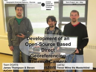
- 1. Geographic Sciences Diploma – Remote Term Project: Jan – May Sensing 2012 Development of an Open-Source Based Direct Georeferencing Thermal Camera Team DGATS: Led by: James Thompson & Steven System Trevor Milne the Mastermind AuCoin
- 2. What is Direct Georeferencing? Source: UNB Geodesy and Geomatics Engineering Lecture Notes; Guide to GPS Positioning (1999).
- 3. Positional Information is post- processed to acquire full benefit from Carrier Phase GNSS The Inertial Measurement Unit and GPS system (PosAV) creates a very accurate path known as Smooth Best Estimate of Trajectory (sbet)
- 4. Sensors Used FLIR A615 Thermal Canon Rebel RGB Camera Camera • FOV = ~45° • FOV = 43-° • Focal length = 13.1 mm • Focal length = 28 mm • Sensor = 8.11 x 10.82 • Sensor = 14.8 x 22.2 mm mm • Spectral range = 7.5 – 13 µm
- 5. Positioning Equipment Applanix Position and Orientation System for Airborne Vehicles (POS AV) 2 1. PCS 1 2. GNSS antenna 3 3. IMU
- 6. Power Requirements Device Amperage Voltage POS AV 2.5 A 24 V Network Hub 1.2 A 12 V Pilot Display 1.5 A 12 V FLIR 2A 12 V RGB 2A 8V Batteries Amp Hours Voltage 2 x 12 VDC 55 A.H. @ 20Hr 24 V 1 x 12 VDC (gel) 51 A.H. @ 20Hr 12 V
- 7. Circuitry • All equipment powered with three 12V batteries • Two 12V batteries wired in series for the POS AV, stored in box 1 • Gel-cell 12V battery used in box 2 for remaining equipment • 12V converted to 8V for the RGB camera
- 8. Box 1 - Schematic
- 9. Box 2 - Schematic
- 10. Software Development Kits System Requirements: C language interface that An IDE which understands recommends using Microsoft ActiveX components eg. Visual Studio for Development Visual Basic, Visual C# projects etc.
- 11. Position and Timing We need to use the POS’s User Datagram Protocol stream to make decisions and to update the Pilot’s onboard display DGATS receives UDP updates once per second IMU records platform attitude 200x per second IMU speed and accuracy are important because the plane speed averages above 50 m/s. GPS signal restrains IMU from ‘drifting’ and gives real world coordinates. The ‘datagrams’ are binary packages of information that require restructuring in DGATS before being used for processing. The information is constantly varying in length and data types. This functionality could not interfere with the user-driven interface, but how?
- 12. A Complex Event Driven Program
- 13. User Interface for a complex event driven program Show picture of DGATS!!!!!!!!!!!!!!!!!!!!!!!!!!!!!!!!!!!!!! !!!!!!!!!!!!!!!!!!!!!!!!!!!!!!!!!!!!!!!!!!!!!!!!!!!!!!!!!!!!!!!!!!!!!!!!!!! !!!!!!!!!!!!!!!!!!!!!!!!!!!!!!!!!!!!!!!!!!!!!!!!!!!!!!!!!!!!!!!!!!!!!!!!!!! !! !!!!!!!!!!!!!!!!!!!!!!!!!!!!!!!!!!!!!!!!!!!!!!!!!!!!!!!!!!!!!!!!!!!!!!!!!!! !!!!!!!!!!!!!!!!!!!!!!!!!!!!!!!!!!!!!!!!!!!!!!!!!!!!!!!!!!!!!!!!!!!!!!!!!!! !! !!!!!!!!!!!!!!!!!!!!!!!!!!!!!!!!!!!!!!!!!!!!!!!!!!!!!!!!!!!!!!!!!!!!!!!!!!! !!!!!!!!!!!!!!!!!!!!!!!!!!!!!!!!!!!!!!!!!!!!!!!!!!!!!!!!!!!!!!!!!!!!!!!!!!! !!
- 14. Planning a Flight Lots of preflight planning and information had to be compiled and either integrated into DGATS or the flight maps. We needed: Sensor specifications: - Sensor size and focal length to calculate image footprints and airbase to ensure correct overlap for our flying height - Equation: fl/ss = H/D Survey specifics and terrain details: - Subject area was the Middleton Transect - AGRG provided LiDAR data for DEM and post-processing Flight details: - Weather and timing were essential. - Expected the morning flight to have best thermal information.
- 15. Middleton Transect Planning Map This was distributed to all the parties involved in the flight. It indicates the primary subject area as well as the lines required (indicative of time). The elevations seen in the DEM overlay posed the next problem. Our system processes and records information in the GPS standard WGS84 datum. Photogrammetric accuracy and the DGATS decisions require height above ground level (AGL) to be used.
- 16. Pilot Display
- 17. Lever Arm Offsets GNSS – IMU IMU – RGB • Initial X, Y, Z • X, Y, Z -5 cm, 0 cm, -87.5 cm 2.5 cm, 0 cm, 37 cm • Calibrated X, Y, Z IMU – FLIR -5 cm, 2.8 cm, -91 cm • X, Y, Z -1.5 cm, 10.5 cm, 37 cm
- 18. Installation Cessna 172 • Single engine • Fixed-wing • Maximum altitude of 14 000 ft. • Maximum speed of 124 ktas
- 19. Installation Mount supports both sensors and the IMU
- 20. Installation Vertically oriented cameras All equipment installed in cargo
- 21. Preliminary Results No electrical malfunctions in flight! Plenty of power! Software functioned flawlessly. Logs successfully recorded events and times. Initial estimates indicate a potential residual of 2 metres for RGB imagery. This is a product of a 40 millisecond delay in the camera events. For context, a blink takes 300-400 milliseconds
- 22. Potential Applications & Future Projects
- 23. Morning NSCC Middleton Campus - Maximum Temp. 38 C
- 24. Afternoon NSCC Middleton Campus - Maximum Temp. 44 C
- 25. River Temperature and Sewage Temperature
- 26. Acknowledgements COGS Trevor Milne, Paul Illsley, Bruce Hicks, Brian Pyke, Dave MacLean, Jim Norton, Dave Wedlock AGRG Dr. Timothy Webster, David Colville, Suzanne Monette, Theresa Constantine-Smith ESET Scott Henderson, Dennis Kingston Greenwood Flight Center Allen Jacob
Notes de l'éditeur
- Images courtesy of Paul Illsley.
- Image courtesy of Paul Illsley.
- Images courtesy of Paul Illsley.
- Image courtesy of Paul Illsley.
- Images courtesy of Paul Illsley.
- Images courtesy of Paul Illsley.