ICT role in 21st century education and its challenges
Multiview drawingtest
1. Page 1 of 15
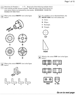
Directions for Numbers s
1- 73 :Read each of the following multiple-choice
items and the possible answers carefully. Mark the letter of the correct answer on
your answer sheet or as instructed by your teacher. REMEMBER: MAKE NO
MARKS ON THIS TEST.
1
What is the correct FRONT view in the figure
below?
3
If a cylinder is cut as illustrated below, the
RIGHT SIDE view will contain a/an:
A Circle.
B Ellipse.
C Rectangle.
D Triangle.
4
2
Which is the correct TOP view in the figure
below?
What is the correct FRONT view in the figure
below?
Go on to next page
2. Page 2 of 15
5
Which statement is MOST accurate concerning
missing lines in the views?
7
Which is the correct RIGHT SIDE view of the
figure below?
A Lines are missing in the top view.
B Lines are missing in the front view.
C Lines are missing in the front and right side
views.
D All three views are complete (no lines
missing).
8
6
What is the correct FRONT view in the figure
below?
Dimension “A” in the TOP VIEW is the:
A Altitude.
B Side to side.
C Bottom to top.
D Front to back.
Go on to next page
3. Page 3 of 15
9
According to its position, view X in the
illustration below is the:
In the figure below, the edge view of surface
12 “A” will appear TRUE LENGTH in the:
A Front.
A Top view.
B Left side.
B Right side view.
C Right side.
C Front view.
D Top.
D All views.
In the figure below, the edge view of surface
10 “A” will appear TRUE LENGTH in the:
What is the correct RIGHT SIDE view of the
13 figure below?
A Bottom view.
B Front view.
C Right side view.
D Top view.
In orthographic projection, lines are formed by
11
Hidden edges are indicated by:
A Alternate, long and then short, dash lines.
B Thick, dark, solid lines.
C Two short dashes followed by one long
dash.
D Uniform
1
8
" long dashes.
14 projecting edges of the object onto planes. The
images formed on the planes are called:
A Views.
B Sides.
C Points.
D Tangencies.
Go on to next page
4. Page 4 of 15
What is the correct TOP view in the figure
15 below?
What is the MINIMUM number of views
18 necessary to describe the three dimensions of
the object below?
A One view
B Two views
C Three views
D Four views
What is the correct TOP view of the figure
16 below?
The term ORTHOGRAPHIC PROJECTION
17 means to:
What is the correct FRONT view of the figure
19 below?
Which of the following is the BEST example of
20 drawing CENTER lines?
A “Throw backward at an angle of 45° and
draw.”
B “Throw forward at an angle of 45° and
draw.”
C “Throw forward at right angles and draw.”
D “Rotate the object at 45° to the picture
plane.”
Go on to next page
5. Page 5 of 15
In the figure below, surface “A” will appear
21 TRUE SIZE and TRUE SHAPE in:
A All of the customary views.
B None of the customary views.
C The front view only.
D The top view only.
What type of line must be drawn between points
24 A & B to complete the LEFT SIDE view of the
figure below?
A Center
B Hidden
C Section
D Visible
What is the correct TOP view in the figure
What is the correct RIGHT SIDE view in the
22 figure below?
25 below?
What is INCORRECT about describing an
23 object?
26 below?
Which is the correct FRONT view of the figure
A Some objects can be described with only
two views.
B Some objects can be described with only
one view.
C The most descriptive view is typically the
top view.
D Use only the number of views necessary to
describe the object.
Go on to next page
6. Page 6 of 15
Where is the HIDDEN LINE drawn
27 INCORRECTLY in the figure below?
What is the correct RIGHT SIDE view in the
28 figure below?
Which is the correct TOP view of the figure
30 below?
What is the correct TOP view in the figure
31 below?
ORTHOGRAPHIC PROJECTION is a
29
The object shown below is composed of:
A Normal surfaces only.
B Normal and inclined surfaces.
C Inclined and oblique surfaces.
D Normal and oblique surfaces.
32 system that allows you to make:
A Three-dimensional drawings of a twodimensional object.
B Two-dimensional drawings of a twodimensional object.
C Two-dimensional drawings of a threedimensional object.
D Three-dimensional drawings of a threedimensional object.
Go on to next page
7. Page 7 of 15
The PRECEDENCE OF LINES tells us that if
33 a visible line and a hidden line coincide (occupy
A fast and accurate method of constructing the
37 side view once the top and front views are
the same position on the drawing), we should:
established is by using a:
A Draw only the hidden line.
A Hidden line.
B Draw only the visible line.
B Miter line.
C Draw the hidden line just above the visible
line.
C Width line.
D Metered line.
D Replace them with a phantom line.
IN MOST CASES, you can completely
The PRECEDENCE OF LINES tells us that if
34 a visible line and a center line coincide (occupy
38 describe the shape and size of an object by
drawing:
the same position on the drawing), we should:
A One view.
A Draw only the center line.
B Two views.
B Draw only the visible line.
C Draw the center line just above the visible
line.
D Replace them with a phantom line.
C Four views.
D Two or three views.
When making a multiview drawing of an object,
39 you need to draw:
When a surface ALWAYS appears as a
35 FORESHORTENED SURFACE (never as a
line) on the six regular planes of projection it is
classified as:
A Only as many views as are needed to
describe the shape.
B Three views.
A Inclined.
C Two views.
B Normal.
D Six views.
C Sloping.
D Oblique.
When making a three-view drawing, all of the
40 following methods can be used to transfer depth
measurements EXCEPT:
According to the correct arrangement of views,
36 the BACK VIEW would be placed adjacent to
the:
A A miter line.
B Dividers.
A Top view.
C A scale.
B Left side view.
D Straight line projection.
C Right side view.
D Bottom view.
Go on to next page
8. Page 8 of 15
When a CURVED SURFACE is TANGENT
41 to a PLANE SURFACE:
The face of the object that has the most
46 descriptive feature(s) should be the:
A No line should be shown where they join.
A Back.
B An edge is formed where they join.
B Front.
C A curved line is produced.
C Right side.
D The curved surface will appear as a hidden
line.
D Top.
The most often used combination of views
42
OBJECT/VISIBLE lines are indicated by:
A Alternate, long ( 3 " to 1 1 " ) and then short
4
2
1
( 16 " to
1
32
" ) dashed lines.
47 includes the:
A Top, front, and right side.
B Top, front, and left side.
B Thick, solid lines.
C Top, front, right side, left side, and back.
C Thin, solid lines.
D Top and right side.
D Uniform
1
8
" dashes.
The number of ORTHOGRAPHIC views
48 provided by the planes of a box is:
43
Which is a CENTER LINE?
A 1.
B 3.
C 6.
D 9.
When making an orthographic drawing, the
49 THICKEST lines should be the:
In a FRONT VIEW, the distance across an
44 object, from one side to other side, is the:
A Altitude.
B Width.
C Height.
D Depth.
A Center lines.
B Visible (object) lines.
C Extension lines.
D Hidden lines.
The FRONT TO BACK dimension of an
50 object is known as the:
45
A MITER LINE is drawn at an angle of:
A Altitude.
A 30º.
B Depth.
B 45º.
C Height.
C 60º.
D Width.
D 90º.
Go on to next page
9. Page 9 of 15
Surfaces and edges that CANNOT be seen from
51 the outside of the object are identified by:
Surfaces or edges that CANNOT be seen in the
56 views are drawn with:
A Hidden lines.
A Centerlines.
B Invisible lines.
B Visible/Object lines.
C Opaque lines.
C Hidden lines.
D Unseen lines.
D No lines.
Another term for ORTHOGRAPHIC
52 DRAWING is:
Orthographic projection involves the use of
57 three planes. They are:
A Isometric drawing.
A Vertical (frontal), profile, and level.
B Oblique drawing.
B Horizontal, vertical (frontal), and profile.
C Multiview drawing.
C Horizontal, profile, and level.
D Perspective.
D Straight, level, and inclined.
Drawings of objects with very little thickness
53 (like an erasing shield) require:
The distance from the BOTTOM of an object to
58 the TOP of the object is:
A One view.
A Circumference.
B Two views.
B Width.
C Three views.
C Height.
D Four views.
D Depth.
In the term “ORTHOGRAPHIC
54 PROJECTION,” the “GRAPHIC” refers to:
How many views should be drawn if the object's
59 thickness is given in a note?
A To throw.
A One
B Forward.
B Two
C Written or drawn.
C Three
D At right angles.
D Six
On a technical drawing, a plane is an imaginary
55 flat surface that has:
In an orthographic drawing, a circular surface
60 may NOT appear as a/an:
A No thickness.
A Ellipse.
B Height and width.
B Circle.
C Depth and height.
C Straight line.
D Very little thickness.
D Parabola.
Go on to next page
10. Page 10 of 15
A line at an angle of less than 90° to a plane of
61 projection will appear as a:
66
The FRONT view consists of:
A Depth and height.
A Point.
B Width and depth.
B True length line.
C Height and circumference.
C Curved line.
D Width and height.
D Foreshortened line.
When a surface slants away from a plane of
62 projection, it appears as a:
67
A Depth and height.
B Width and depth.
A Foreshortened surface.
C Height and circumference.
B Foreshortened line.
D Width and height.
C Normal surface.
D True-shaped surface.
68
63
B Width and depth.
C Height and circumference.
B Angle, height, and depth
D Width and height.
C Height, width, and depth
D Angle, depth, and radius
69
B Frontal plane.
A Depth and height.
C Vertical plane.
B Width and depth.
D Profile plane.
C Height and circumference.
D Width and height.
70
65
A Height and depth.
B Width and height.
C Height and length.
The RIGHT SIDE view is taken from the:
A Horizontal plane.
The LEFT SIDE view consists of:
The REAR view consists of:
The TOP view consists of:
A Depth and height.
What three dimensions do all objects have?
A Height, width, and radius
64
The RIGHT SIDE view consists of:
CENTER lines should be:
A Thick.
B Medium thick.
C Thin.
D Very thin, very light.
D Width and length.
Go on to next page
11. Page 11 of 15
71
HIDDEN lines should be:
A Thick.
B Medium thick.
C Thin.
D Very thin, light lines.
72
The TOP VIEW is normally placed above the:
A Right side.
B Front.
C Left side.
D Back.
73
When two surfaces intersect they form a:
A Line.
B Point.
C Solid.
D Surface.
When a surface ALWAYS appears as a
74 FORESHORTENED SURFACE (never as a
line) on the six, regular planes of projection it is
classified as what type of surface?
A Inclined
B Normal
C Sloping
D Oblique
The slot in Figure D1005.02.02 above is hidden
75 in the:
A Front view.
B Top view.
C Left side view.
D Bottom view.
Go on to next page
12. Page 12 of 15
Directions for Numbers s
76- 98 :Read each of the following multiple-choice
items and the possible answers carefully. Mark the letter of the correct answer on
your answer sheet or as instructed by your teacher. REMEMBER: MAKE NO
MARKS ON THIS TEST.
What type of surface is EFG in Figure
79 D1005.02.04 above?
A Frontal
B Horizontal
C Inclined
D Profile
What type of surface is GHJ in Figure
80 D1005.02.04 above?
Figure D1005.02.04
A Frontal
B Horizontal
How will surface ADEG in Figure
C Inclined
view?
D Profile
76 D1005.02.04 above appear in the RIGHT SIDE
A True size and shape
B As an edge
C Foreshortened
D Skewed
What type of surface is CJL in Figure
81 D1005.02.04 above?
A Frontal
B Horizontal
C Inclined
What type of surface is ABCG in Figure
77 D1005.02.04 above?
D Profile
A Frontal
B Horizontal
C Inclined
D Profile
What type of surface is FHLK in Figure
82 D1005.02.04 above?
A Frontal
B Horizontal
C Inclined
What type of surface is ADEG in Figure
78 D1005.02.04 above?
D Profile
A Frontal
B Horizontal
C Inclined
D Profile
Go on to next page
13. Page 13 of 15
What type of surface is HJL in Figure
83 D1005.02.04 above?
A Frontal
B Horizontal
C Inclined
D Profile
What type of surface is CJG in Figure
84 D1005.02.04 above?
Figure D1005.02.02
A Frontal
B Horizontal
C Inclined
D Oblique
The hole in Figure D1005.02.02 above is
88 visible in the:
A Bottom view.
B Front view.
How will surface ADEG in Figure
85 D1005.02.04 above appear in the TOP view?
C Left side view.
D Right side view.
A True size and shape
B As an edge
C Foreshortened
D Skewed
The slot in Figure D1005.02.02 above is visible
89 in the:
A Bottom view.
B Rear view.
How will surface HJL in Figure D1005.02.04
86 above appear in the BACK view?
C Left side view.
D Right side view.
A True size and shape
B As an edge
C Foreshortened
D Skewed
The hole in Figure D1005.02.02 above is
90 hidden in the:
A Front view.
B Left side view.
How will surface HJL in Figure D1005.02.04
87 above appear in the RIGHT SIDE view?
C Rear view.
D Pictorial view.
A True size and shape
B As an edge
C Foreshortened
D Skewed
Go on to next page
14. Page 14 of 15
94
Line F in the figure above is a/an:
A Visible (Object) line.
B Square line.
C Center line.
D Hidden line.
Figure D1005.01.01
91
Line AB in the figure above is a/an:
A Square line.
B Miter line.
C Isometric line.
Figure D1005.02.01
D Perpendicular line.
92
Line CD in the figure above is a/an:
A Isometric line.
B Center line.
C Hidden line.
D Visible line.
93
Line E in the figure above is a/an:
A Center line.
Which line in the figure above is parallel to the
95 DEPTH of the object?
A AB
B CD
C EF
D AF
Which line is parallel to the HEIGHT of the
96 object shown above?
B Visible line.
A AB
C Square line.
B CD
D Hidden line.
C EF
D AF
Go on to next page
15. Page 15 of 15
Figure D1005.02.03
Which is the FRONTAL surface in Figure
97 D1005.02.03 above?
A 2
B 3
C 4
D 5
Which is the PROFILE surface in Figure
98 D1005.02.03 above?
A 2
B 3
C 4
D 5
Stop here