Gaviotas Hydraulic Ram Installation Guide
•
1 j'aime•2,154 vues

Gaviotas Hyidraulic Ram Pump: Installation, Operation and Maintenance Manual

Recommandé
Recommandé
Contenu connexe
Tendances
Tendances (20)
Similaire à Gaviotas Hydraulic Ram Installation Guide
Similaire à Gaviotas Hydraulic Ram Installation Guide (20)
Plus de Fatin62c
Plus de Fatin62c (20)
Dernier
Dernier (20)
Gaviotas Hydraulic Ram Installation Guide
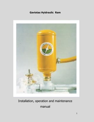
- 1. 1 Gaviotas Hyidraulic Ram Installation, operation and maintenance manual
- 2. 2 Installation, operation and maintenance manual Gaviotas Center’s design, performance and coordination Reproduction in whole or in part is not prohibited; we rather stimulate it, as long as proper reference to the Centro "Las Gaviotas" is done.
- 3. 3 Installation, operation and maintenance manual INTRODUCTION The technological development of the "Gaviotas” High head type HYDRO ARIETE was performed based on the experience and operation of it, on a number of different working conditions, so it has been redesigned and changed during a long time. Today it is an implement of high reliability requiring minimum maintenance. It is required only water and a small drop or waterfall of 1 to 4 meters for operating these pumps without a motor. It pumps thousands of gallons of water, day and night, at a maximum distance of 1000 meters with a height of 100 meters, without consuming electricity or fuel. For its innovative design, manufacturing and maintenance, it is a more efficient Hydro ram than the traditional one.
- 4. 4 Installation, operation and maintenance manual Table of contents GENERAL DESCRIPCIÓN............................................................ 1 FUNCIONING................................................................................... 1 GAVIOTAS HYDRÁULIC RAM PARTS................................... 2 GAVIOTAS HYDRÁULIC RAM ENSAMBLE …. ................... 3 INSTALLATIÓN REQUIREMENTS………................................ 4 WATER FALL…….......................................................................... 5 FLOW SUPLY CHART………………........................................... 6 INSTALLATIÓN MODELS........................................................... 7 RECOMMENDATIONS.................................................................. 9 RAM MANTENANCE………………............................................. 11
- 5. 5 Installation, operation and maintenance manual General description The hydraulic ram is an automatic pump for lifting water. It was designed and developed for taking advantage of small waterfalls with little flow using the only energy of the water force of a small pound or creek. Functioning The falling water into the reservoir (Q) through the feed pipe increases its speed (d) makes the force of the water close the valve button (I); it acquires suddenly much more pressure, opening the high pressure seal (D) and entering the camera air (T), whose air momentarily compressed will expand closing (D) and driving the water to the upper reservoir, (I) the water then descends by its own weight and so it begins another cycle. d: Supply pipe m: Feed hose I: Valve Q available flow Qo: Wasted flow T: Air chamber a: Surge tank h: Waterfall (m) q: Delivery rate (l / min) D: High pressure seal Ho: Pumping Height (m) I: Pumping length (m)
- 6. 6 Installation, operation and maintenance manual The Gaviotas Hydraulic Ram parts 1. Air chamber 2. Retainers nut fixing 3. Retainer 4. High pressure sealing 5. Release valve body 6. Mesh (filter) 7. Galvanized tee Ø1-1/4” 8. Zinc screw Ø3/8” x 2-1/2” 9. Aluminums base 10. Rubber gasket 11. Valve 12. Waste valve body 13. Zinc nuts Ø3/8” 14. Valve’s rubber 15. Hexagonal nut (weight)
- 7. 7 Installation, operation and maintenance manual Gaviotas Hydraulic Ram Ensamble Unloading valve parts A Pin B Retainer C Retainer nut D High pressure sealing E Unloading valve body F Mesh O Ear Waste valve parts G Waste valve body H Rubber packing I Valve J Zinc nuts Ø 3/8” K Hexagonal nut (weight) L Valve rubber Air Chamber Sacrificial anode Unloading valve Waste valve Galvanized valve Te Ø 1-1/4 Aluminum base
- 8. 8 Installation, operation and maintenance manual Mounting requirements The Hydraulic Ram requires The ram has a range of daily 12,000 l to 10 meter high or 1,000 l to 100 ms (see supply chart) The maximum pump length (Lo) 1,000 A natural or artificial waterfall from 1 to 4 m An available flow (Q) of 40 /l/min) equivalent to 4 buckets/min The length of the galvanized pipe (d) should be 6 ms and the diameter 1-1/4” The waste flow (Qo) must have a drain so that the ram do not flood If any of these requirements are not present or do not comply, do not install the ram pump l l l l
- 9. 9 Installation, operation and maintenance manual Waterfall As noted above, The striker requires a drop of water (h) at least 1 meter, and up to 4 meters high. Generates a smaller drop operation unstable and more wear or breakage occurs pulsating valve (I). · The ideal setup is to allowing the tube supply (d) to lie horizontally on the ground · The rum pump consumption depends of: · The available decline in water (h) • The pumping height (Ho) · The valve stroke pulsating · The magnitude of the weight of the hexagonal nut In case the installation place does not allow placing the ram and feeding tubing horizontally, a water flow consisting of a tilt less than 10 º is acceptable. · When available flow (Q) is taken from a stream, is necessary to install the ALMENARA or surge tank (a) that has its level at outdoors. This ALMENARA not aims to store large amounts of water, but rather as a buffer that absorbs any sudden increase in pressure in the pipes and avoid the ram stop working.
- 10. 10 Installation, operation and maintenance manual Flow Supply Chart Q: l/day ~ Available waterfallHo:ms H:ms ••• 1.0 1.5 2.0 2.5 3.0 3.5 4.0 H 10 2419 4060 5357 6566 8467 9676 12096 i 15 1987 2678 3802 4925 6134 7776 9245g h 20 1642 2085 3024 3888 5184 5875 7258 25 1123 1729 2333 3283 4147 5141 5875 30 734 1210 1987 2808 3456 4060 4838 40 475 950 1541 2160 2592 3370 3715 50 648 1282 1814 2074 2506 2851 60 518 907 1296 1728 2074 2506 70 778 1037 1296 1642 1814 80 634 864 1123 1334 1555 90 691 994 1209 1382 100 800 1037 1296 Note Water leaks each 100 meters about 15% of the water supply.
- 11. 11 Installation, operation and maintenance manual Installation Models Characteristics Each meter waterfall pushes up 25 m Maximum fall 4 ms Minimum fall 1 m Maximum pump length 1000 ms Minimum available flow Gaviotas hydraulic ram installation model PVC pipe Ø 4” PVC welded cap Ø2” PVC pipe pres. Ø2” PVC bend pres. Ø2” x 4.5” PVC welded hub Ø4” x 2” Galvanized pipe Ø1”-1/4” x 6 m Tap Ø1”-1/4” Galvanized Nipple Ø1”-1/4”x 20 cm Threaded hub Ø1” clamp Ø1” clamp Supply Hose Ø1/2” Cheque Ø1/2” Galvanized Nipple Ø1/2”x 20 cm 10 m high pressure hose Ø3/4” Galvanized Nipple Ø 1-1/4”x 30 cm Galvanized universal Ø 1-1/4” PVC Tee pres. Ø4” PVC welded hub Ø4” x 2”
- 12. 12 Installation, operation and maintenance manual Two Gaviotas hydraulic rams model installation Installacion model of four Gaviotas hydraulic ram Inlet outlet Inlet Outlet
- 13. 13 Recommendations It is essential to place a high pressure hose of 2 meters in length, At the air camera output (T) before tying conduction hose (m). Failure to do that and wrongly placed a rigid or galvanized PVC pipe section makes the pneumatic chamber explodes due to vibration. On the other part connecting directly to the camera air, makes this hose burst due to the pressure generated. To avoid solid particles or elements in the inlet of the ram through the water, Gaviotas supplies a filter which must be installed inside to a height of 20 cm above the tanks ground. Avoid any obstruction of the ear, a vent (O) in the body of the unloading valve (E) It is convenient to fix the conduction pipe (d) in two or more points at leastfor avoiding damaging vibration to the thread. Avoid leaks in both between parts of the ram as well as in the pipeline conduction (d) to avoid pressure loss, use Teflon around threads and ties. Connect correctly conductive hose (m) to avoid loss of flow and pressure. 20 cm Ø1” clampØ1” clamp Ø1/2”Conduction pipe 2meters high pressure hose Ø3/4”
- 14. 14 Installation, operation and maintenance manual Fix the body or the base of the ram in a block of concrete 30 cm. x 30 cms. surface and 50 cm depth with two screws anchor Ø 3 / 8 "x 6" submerged 4 " in the concrete and at 15.2 cm distance between screws. · In its design you have to take into account the uniform distribution of the water in the whole area previous to the entrance into the sand trap so that not suddenly burst of water can cause alterations in the sedimentation area · Frequently the water coming from a shallow source has solid elements such as sand, peels, shells, leaves, and slags that do not decompose or crumble. If these materials are not eliminate could cause damage or disturbance in the system due to deterioration of the waste and unloading valves, as well as the obstruction of the feed pipe (see chart 1) • The conductive hose (m) installed on wavy land produce air bags, a phenomenon that increases artificially the pumping height (Ho), and therefore, reduces the final water supply volume (q). Try driving the hose (m) on a flat trajectory or a continuous albeit longer rise. · Keep the recommended fall (h) at least to 1 meter or maximum 4 meters. Construction of the sand trap: · Sand traps are horizontal ponds, that keep the outgoing flow equal to the input, i.e. a continuous flow, and hence it’s important function.
- 15. 15 Installation, operation and maintenance manual Hydraulic ram maintenance If the ram stop working or does not supply enough water these are the possible causes Problem No air in the air chamber Cause No air in the air chamber due to obstruction in the ear. It is necessary that this ear does not have any obstruction so it can allow the air coming into the chamber to receive the beat from the water into de impulsion pipe so that no breakage occurs in the pipe or in the welding that prevent the spoiling of the ram. Solution Make sure that the vent, ear (O) in the body of the unload valve for supplying air never be obstructed. River or wellspring water Sand trap Overflow Level 1.04 ms Reference O ms
- 16. 16 Installation, operation and maintenance manual Problem The high pressure sealing (D) in the unload valve inside the air chamber is worn out and needs to be changed. Cause The high pressure sealing is worn, crystallized or oval. Solution Unscrew the inner tube and check out the seal if it is in good condition, if not replace it with a new one. Problem There is a limited amount of water in the feeding flow (q) Cause The running of the valve is too long and the ram needs more water than the available one. Solution You must accelerate the drive of the valve (I) and diminish the running that way you can supply more water and not too much affecting the ram.
- 17. 17 Installation, operation and maintenance manual Las Gaviotas Center Colombian Orinoquia Warranty Las Gaviotas designer and manufacturer of the high head Hydraulic Ram warrants any proved useless part due to failure in material or fabrication for a year time after the installation Ram Nº _________ Date of Sale_______ Bill Number_______
- 18. 18 Installation, operation and maintenance manual Gaviotas, this world there was arising spontaneously from chaos to cosmos, always believing in freedom, without a predetermined pattern different from that of sustainability. Human race was originated in the tropics and in the tropics must other homo sapiens be reborn, to help meet the extinction, this fact is vital, above all, he has to love life, and he has to be capable of illuminating the future. Paolo Lugari "Maturity means making our dreams come true." For more information on other projects, visit Gaviotas Centre website
- 19. 19 Installation, operation and maintenance manual Notes
- 20. 20 Paseo Bolivar Nº 20-90 Tels. 571- 286287618261 FAX 571.2811803/3363632 A.A. 3419967 Web page www.centrolasgaviotas.org Bogotá C.D. Colombia