
Recommandé
Recommandé
Contenu connexe
Tendances
Tendances (20)
Similaire à Using A Hydraulic Ram to Pump Livestock Water
Similaire à Using A Hydraulic Ram to Pump Livestock Water (20)
Plus de Fifi62z
Plus de Fifi62z (15)
Dernier
Dernier (20)
Using A Hydraulic Ram to Pump Livestock Water
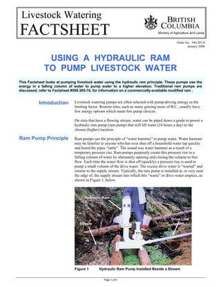
- 1. Page 1 of 6 Livestock Watering Order No. 590.305-9 January 2006 USING A HYDRAULIC RAM TO PUMP LIVESTOCK WATER Introduction Ram Pump Principle Livestock watering pumps are often selected with pump-driving energy as the limiting factor. Remote sites, such as many grazing areas of B.C., usually have few energy options which mean few pump choices. On sites that have a flowing stream, water can be piped down a grade to power a hydraulic ram pump (ram pump) that will lift water (24 hours a day) to the chosen (higher) location. Ram pumps use the principle of “water hammer” to pump water. Water hammer may be familiar to anyone who has ever shut off a household water tap quickly and heard the pipes “rattle”. The sound was water hammer as a result of a temporary pressure rise. Ram pumps purposely create this pressure rise in a falling column of water by alternately opening and closing the column to free flow. Each time the water flow is shut off (quickly) a pressure rise is used to pump a small volume of the drive water. The excess drive water is “wasted” and returns to the supply stream. Typically, the ram pump is installed at, or very near the edge of, the supply stream into which this “waste” or drive water empties, as shown in Figure 1, below. Figure 1 Hydraulic Ram Pump Installed Beside a Stream Drive Line Stream Hydraulic Ram This Factsheet looks at pumping livestock water using the hydraulic ram principle. These pumps use the energy in a falling column of water to pump water to a higher elevation. Traditional ram pumps are discussed; refer to Factsheet #590.305-10, for information on a commercially-available modified ram .
- 2. Page 2 of 6 Ram Operation Waste Valve Open Waste Valve Closed Ram Performance Ram pumps are available from various manufacturers, can be homemade, may appear different, but they operate the same. Figure 2, below, illustrates the operation cycle of a hydraulic ram pump. This cycle repeats from 40 to 60 times per minute; pumping is continuous 24 hours a day. See also Figure 3, next page, for a schematic of a typical installation. -waste valve open -drive water flows back to ‘waste’ (to stream) -water velocity increasing -discharge valve is closed -pressure in air chamber moves delivery water -water is pumped up delivery pipe to trough -waste valve closes due to high water velocity -drive water cannot stop instantaneously -therefore pressure opens discharge valve -water goes into air chamber, compressing air -drive pipe pressure is then reduced -waste valve re-opens and cycle re-starts Figure 2 Hydraulic Ram Pump Operation There is an energy balance between the Drive and Delivery sides of a Ram Pump. Using Figure 3, next page, the Fall (F) times the Drive Water Volume (Dw) and times the Pump Efficiency (Eff%; use Table 1, next page), equals the Lift (L) times the Pumped Water Volume (Pw): F x Dw x Eff% = L x Pw Therefore, Pumped Water Volume (Pw) can be estimated by: Pw = Eff% x F x Dw L • consistent units must be used (i.e., feet and US gpm, or m and L/min) • for simplicity, the pipeline friction losses are not considered
- 3. Page 3 of 6 Ram Selection Figure 3 Hydraulic Ram Pump Installation Schematic Estimating Ram Efficiency. Ram pump operation efficiency changes depending on the relationship of Fall to Lift, as shown in Table 1, below. For example, a site with a Lift of 30 m and a Fall of 5 m has a L / F ratio of 6, and from Table 1 a Ram Pump can be expected to operate at an efficiency of 75 % in those conditions. Note that efficiency is reduced as the Lift to Fall ratio increases (higher Lift compared to Fall). TABLE 1 EFFICIENCY OF COMMERCIAL HYDRAULIC RAM PUMPS* BASED ON THE RATIO OF LIFT (L) TO FALL (F) L / F Ratio Efficiency % L / F ratio Efficiency % 3 85 10 60 4 80 11 60 5 75 12 55 6 75 13 45 7 70 14 40 8 65 15 40 9 65 * Unless tested, assume ½ of these efficiencies for home built ram pumps from New Zealand Ministry of Agriculture and Fisheries, Factsheet AST 67, 1985 Two selection methods may be used; by table output or by manufacturers’ information. A selection example is given on page 5. Estimating Output. Table 2, next page, can be used to estimate the output of a Ram Pump when the Fall, Lift, and Drive Water flow rate are known: • locate the Lift (L) and the Fall (F) on the table • select the Pump Output (Pw) for 1 litre per minute Drive Water rate (Dw) • multiply this output by the actual Drive Water rate used Manufactures Output. Commercial Ram Pumps are sized by the Drive Pipe diameter, which in turn is sized by the Drive Water flow rate. Most all makes of Ram Pumps of a given size use the same flow rate. To select a commercial ram pump, use manufacturers’ information. Table 3, next page, gives approximate Ram Pump characteristics. Drive Water Source Ram Pump Drive Pipe containing Drive Water (Dw) Delivery Pipe containing Pumped Water (Pw) Fall (F) Lift (L) DRIVE SIDE DELIVERY SIDE
- 4. Page 4 of 6 TABLE 2. ESTIMATING HYDRAULIC RAM PUMP 24 HOUR OUTPUT 1 (Litres per day) Lift (L) Above Ram 2 (metres) 5 7.5 10 15 20 30 40 50 60 80 100 125 Fall (F) to Ram 2 (metres) Litres per Day Pumped (Pw) at a Drive Flow Rate (Dw) of 1 Liter per Minute 3 1 216 134 87 33 29 20 14 1.5 216 162 86 54 29 22 17 2 307 216 134 86 38 29 23 19 14 2.5 408 270 180 117 66 36 29 24 18 14 3 367 216 151 87 49 34 29 22 17 14 3.5 269 189 109 57 40 34 25 20 16 4 307 216 134 86 63 38 29 23 18 5 408 288 180 117 86 66 36 29 23 6 367 216 151 112 86 54 34 28 7 269 189 141 109 76 40 32 8 216 173 134 86 58 37 9 259 194 151 105 78 41 10 288 216 180 117 86 58 12 367 276 216 162 112 83 14 343 269 189 141 105 16 307 216 172 120 18 367 259 194 145 20 288 216 173 1 pump efficiencies shown in Table 1 are incorporated into these table output rates 2 these are the elevations between supply point and ram & ram and delivery point - not pipe lengths 3 multiply the Table Output by the actual Drive Flow Rate of the system to estimate the actual system output Multiply metres by 3.28 for feet: Divide litres by 3.785 for US gallons adapted from New Zealand Ministry of Agriculture and Fisheries, Factsheet AST 67, 1985 TABLE 3. TYPICAL HYDRAULIC RAM PUMP SIZES AND APPROXIMATE CHARACTERISTICS Drive Pipe Delivery Pipe Water Flow Rates Pumped (Pw) 3 Length2 (m) 1 Ram Size Diameter (mm) 1 min max Diameter (mm) 1 Drive (Dw) minimum (L/min) 1 maximum (L/min) 1 range (1000 L/day) 1 ¾ 18 3 18 13 7.5 2.6 up to 3.8 1 25 4 25 13 23 5.3 0.4 to 7.5 1½ 38 6 38 18 53 10.6 0.5 to 15 2 50 7.5 50 25 95 19 1.3 to 26 2½ 63 10 63 31 130 26.5 2 to 37 3 75 11 75 38 230 53 2.6to 75 6 150 22 150 75 570 190 3.8 to 270 1 Divide mm by 25 for inches; Multiply m by 3.28 for feet; Divide litres by 3.785 for US gal 2 Drive Pipe is to be from minimum 150, and maximum 1,000, times its diameter 3 Pumped Water will be greatest at lowest lifts – refer to Table 1 for estimation of volume versus lift
- 5. Page 5 of 6 Ram Installation Ram Selection Example. A site requires 4,000 litres per day to be pumped a Lift of 30m. The Drive Water supply is 25 litres per minute with a Fall of 5m to the ram pump. What size of Ram Pump should be chosen? • from Table 2, a 30m Lift and a 5m Fall = 180 litres / day / litre supply • with 25 L/m supply, the daily pump rate is 180 x 25 = 4500 L/day • from Table 3, a 1 inch ram size would be chosen - it requires 23 L/min Drive Water supply (the site has 25) - it will pump the supply required (5.3 L/min x 60 min x 24 hrs = 7632 L/day) - it will need a 25mm Drive Pipe that is between 4 and 25m long - the delivery pipe diameter is 13mm The following are guidelines for Ram Pump installations. The Drive Water. A ram pump can only be considered on sites that have particular water characteristics. To drive a Ram Pump, the site must have: • sufficient water volume, and • sufficient fall in a ‘reasonable’ distance (gradient) Typical streams at a low gradient (near level), say 1% (1m per 100m), will require significant water delivery line piping to place the pump at the required fall below the water intake. Preferred sites have the fall in as short a distance as possible (i.e., close to the required Drive Pipe length). On low gradient sites, it may be preferred to pipe the Drive Water to a surge tank. From there the Drive Pipe can be installed at the correct length and grade to the ram pump, as shown in Figure 4, page 6. The Drive Pipe. Drive pipe requirements are important to achieve the correct water flow and pressure conditions to power the pump. To pump the desired amount of water, the Drive Pipe must: • have the required Fall to the pump • have a length from 6 to 12 times the Fall (F) - also, between 150 and 1,000 times its diameter (a wide range but gives guidance) • be sized to match the Drive Water flow required, and • be of steel or schedule 40 PVC to withstand pressures encountered The Delivery Pipe and Lift. Other installation guidelines: • Lift (L) must be 6 to 12 times the Fall (F) - this is to ensure correct back pressure on the pump • Delivery Pipe diameter is usually ½ of the Drive Pipe diameter
- 6. Page 6 of 6 Using a Surge Tank. If the Drive Pipe gradient that is required is greater than the natural gradient of the stream, a surge tank system must be used. The gravity water supply from the stream will have an intake far up the stream, where the head is sufficient to flow the required Drive Water. This flow is piped to a surge tank that is located on the required gradient above the Ram Pump. Refer to Figure 4, below. A surge tank separates the Drive Pipe requirements from the restrictions of a low gradient stream. On very low gradient streams where a high lift of water is desired, this requirement may make a ram pump a poor choice due to these extra Drive Water costs. Figure 4 Surge Tank Supplying Drive Water to Hydraulic Ram Pump RESOURCE MANAGEMENT BRANCH WRITTEN BY Ministry of Agriculture and Lands Lance Brown 1767 Angus Campbell Road Engineering Technologist Abbotsford, BC V3G 2M3 Phone: (604) 556-3100 Kamloops Office Hydraulic Ram Pump at Stream (see Figure 1) Steel Drive Pipe from Surge Tank to Ram Surge Tank Drive Water into Surge Tank by Gravity Flow from Stream