1. ZJ WHEELS AND TIRES 22 - 1
WHEELS AND TIRES
CONTENTS
page page
SPECIFICATIONS . . . . . . . . . . . . . . . . . . . . . . . . 12 VEHICLE VIBRATION . . . . . . . . . . . . . . . . . . . . . 10
TIRES . . . . . . . . . . . . . . . . . . . . . . . . . . . . . . . . . . 1 WHEELS . . . . . . . . . . . . . . . . . . . . . . . . . . . . . . . . 6
TIRES
INDEX
page page
Cleaning of Tires . .. . . . . . . . . . . . . . . . . . . . . . . . 2 Rotation . . . . . . . . . . . . . . . . . . . . . . . . . . . . . . . . . 3
General Information . . . . . . . . . . . . . . . . . . . . . . . . 1 Tire Inflation Pressures . . . . . . . . . . . . . . . . . . . . . . 2
Pressure Gauges . .. . . . . . . . . . . . . . . . . . . . . . . . 2 Tire Noise or Vibration . . . . . . . . . . . . . . . . . . . . . . 4
Repairing Leaks . . .. . . . . . . . . . . . . . . . . . . . . . . . 3 Tire Wear Patterns . . . . . . . . . . . . . . . . . . . . . . . . . 4
Replacement Tires .. . . . . . . . . . . . . . . . . . . . . . . . 2 Tread Wear Indicators . . . . . . . . . . . . . . . . . . . . . . . 3
GENERAL INFORMATION Performance tires will have a speed rating letter
Tires are designed for each specific vehicle. They after the aspect ratio number. The speed rating is not
provide the best overall performance for normal oper- always printed on the tire sidewall. The letter S in-
ation. The ride and handling characteristics match dicates that the tire is speed rated up to 112 mph.
the vehicle’s requirements. With proper care they • Q up to 100 mph
will give excellent reliability, traction, skid resis- • T up to 118 mph
tance, and tread life. These tires have specific load • U up to 124 mph
carrying capacities. When correctly inflated, they will • H up to 130 mph
operate properly. • V up to 149 mph
Tires used in cool climates, and with light loads • Z more than 149 mph (consult the tire manufac-
will have a longer life than tires used in hot climates turer for the specific speed rating)
with heavy loads. Abrasive road surfaces will acceler- An All Season type tire will have either M + S, M
& S or M—S (indicating mud and snow traction) im-
ate tire wear.
printed on the side wall.
Driving habits have more effect on tire life than
any other factor. Careful drivers will obtain much RADIAL-PLY TIRES
greater mileage than careless drivers. Radial-ply tires improve handling, tread life, ride
Driving habits that shorten the life of any tire; quality and decrease rolling resistance.
• Rapid acceleration and deceleration Radial-ply tires must always be used in sets of
• Severe application of brakes four. Under no circumstances should they be used on
• High-speed driving the front only. They may be mixed with temporary
• Taking turns at excessive speeds spare tires when necessary, but reduced speeds are
• Striking curbs and other obstacles recommended.
It is very important to follow the tire rotation in- Radial-ply tires have the same load-carrying capac-
terval ity as other types of tires of the same size. They use
the same recommended inflation pressures.
IDENTIFICATION
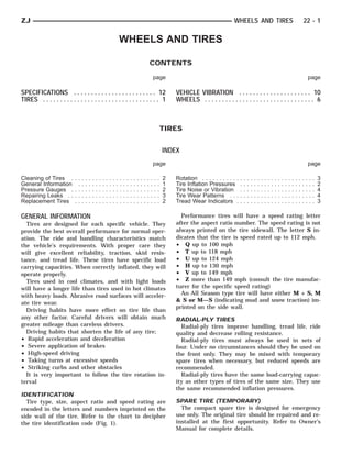
Tire type, size, aspect ratio and speed rating are SPARE TIRE (TEMPORARY)
encoded in the letters and numbers imprinted on the The compact spare tire is designed for emergency
side wall of the tire. Refer to the chart to decipher use only. The original tire should be repaired and re-
the tire identification code (Fig. 1). installed at the first opportunity. Refer to Owner’s
Manual for complete details.
2. 22 - 2 WHEELS AND TIRES ZJ
Fig. 2 Under Inflation Wear
Fig. 1 Tire Size Identification
TIRE CHAINS
Tire snow chains may be used on certain models.
Refer to Owner’s Manual for more information.
CLEANING OF TIRES Fig. 3 Over Inflation Wear
Steam cleaning may be used for cleaning.
DO NOT use gasoline or wire brush for cleaning. checked cold once per month. Tire pressure de-
DO NOT use mineral oil or an oil-based solvent. creases when the outside temperature drops.
Inflation pressures specified on the placards are al-
PRESSURE GAUGES ways cold inflation pressure. Cold inflation pres-
High-quality, dial-type, air-pressure gauges are rec- sure is obtained after the vehicle has not been
ommended. After checking with the gauge, replace operated for at least 3 hours. Tire inflation pressures
valve cap finger tight. may increase from 2 to 6 pounds per square inch
(psi) during operation. Do not reduce this normal
TIRE INFLATION PRESSURES pressure build-up.
Under inflation (Fig. 2) causes rapid shoulder wear Vehicles loaded to maximum capacity should not be
and tire flexing. driven at continuous speeds above 75 mph (120 km/
Over inflation (Fig. 3) causes rapid center wear and h).
loss of the tire’s ability to cushion shocks.
Improper inflation can cause; WARNING: OVER OR UNDER INFLATED TIRES CAN
• Uneven wear patterns AFFECT VEHICLE HANDLING AND CAN FAIL SUD-
• Reduced tread life DENLY, RESULTING IN LOSS OF VEHICLE CON-
• Reduced fuel economy TROL.
• Unsatisfactory ride
• Cause the vehicle to drift
Refer to the Owner’s Manual for information re- REPLACEMENT TIRES
garding proper tire inflation pressure. OEM tires provide a proper balance of many fea-
This pressure has been carefully selected to provide tures such as;
for safe vehicle operation. Tire pressure should be • Ride
3. ZJ WHEELS AND TIRES 22 - 3
• Noise
• Handling
• Durability
• Tread life
• Traction
• Rolling resistance
• Speed capability
Original equipment tires should be used when re-
placement is needed. Failure to use original or equiv-
alent replacement tires, may adversely affect the
handling of the vehicle.
Refer to the placard on the vehicle or the
Owner’s Manual for the correct replacement
tire.
The use of oversize tires is not recommended.
They may cause interference with vehicle suspension
and steering travel. This can cause tire damage or
failure.
WARNING: FAILURE TO EQUIP THE VEHICLE WITH
TIRES HAVING ADEQUATE LOAD CAPABILITY CAN Fig. 5 Tread Wear Indicators
RESULT IN SUDDEN TIRE FAILURE.
REPAIRING LEAKS
For proper repairing, a radial tire must be removed
ROTATION from the wheel. Repairs should only be made if the
Front and rear tires, operate at different loads and puncture is in the tread area (Fig. 6). If outside the
perform different steering, driving, and braking func- tread area the tire should be replaced.
tions. For these reasons, the tires wear at unequal
rates. They may also develop irregular wear pat-
terns. These effects can be reduced by rotating the
tires according to the maintenance schedule in the
Owners Manual. This will improve tread life, traction
and maintain a smooth quiet ride.
The suggested method of tire rotation is the same
side front to rear pattern (Fig. 4). Other rotation
methods can be used, but may not provide the same
tire longevity benefits.
Fig. 6 Tire Repair Area
Fig. 4 Tire Rotation Pattern
Deflate tire completely before dismounting tire
TREAD WEAR INDICATORS from the wheel. Use lubrication such as a mild soap
Tread wear indicators are molded into the bottom solution when dismounting or mounting tire. Use
of the tread grooves. When tread is 1.6 mm (1/16 in.), tools free of burrs or sharp edges.
the tread wear indicators will appear as a 13 mm Before mounting tire on wheel, make sure all rust
(1/2 in.) band. scale is removed from the rim. Repaint or seal if nec-
Tire replacement is necessary when indicators ap- essary.
pear in two or more grooves (Fig. 5).
4. 22 - 4 WHEELS AND TIRES ZJ
Fig. 7 Abnormal Tire Tread Wear Patterns
TIRE NOISE OR VIBRATION Excessive camber causes the tire to run at an angle
The radial-ply tire on your vehicle is more sensitive to the road. One side of tread is worn more than the
to improper mounting, or imbalance. other.
To determine if tires are the cause of vibration, Excessive toe-in or toe-out causes wear on tread
drive the vehicle over a smooth road at different edges. There is a feathered effect across the tread
speeds. Note the effect of acceleration and decelera- (Fig. 7).
tion on noise level. Differential and exhaust noise
will change in intensity as speed varies. Tire noise
will usually remain constant.
TIRE WEAR PATTERNS
Under inflation will increase wear on the shoulders
of the tire. Over inflation will increase wear at the
center of the tread.
5. ZJ WHEELS AND TIRES 22 - 5
LEAD CORRECTION CHART
6. 22 - 6 WHEELS AND TIRES ZJ
WHEELS
GENERAL INFORMATION
Original equipment wheels are designed for the
specified Maximum Vehicle Capacity.
All models use steel or cast aluminum drop center
wheels. The safety rim wheel (Fig. 1) has raised sec-
tions between the rim flanges and the rim well.
Fig. 2 Lug Nut Tightening Pattern
• Excessive runout
• Bent or dented
• Leak air through welds
• Have damaged bolt holes
Wheel repairs employing hammering, heating, or
welding are not allowed.
Original equipment wheels are available through
Fig. 1 Wheel Safety Rim your dealer. Replacement wheels from any other
Initial inflation of the tire forces the bead over source should be equivalent in:
these raised sections. In case of tire failure, the • Load carrying capacity
raised sections hold the tire in position on the wheel • Diameter
until the vehicle can be brought to a safe stop. • Width
Cast aluminum wheels require special balance • Offset
weights and alignment equipment. • Mounting configuration
Failure to use equivalent replacement wheels may
WHEEL INSTALLATION affect the safety and handling of your vehicle. Re-
The wheel studs and nuts are designed for specific placement with used wheels is not recommended.
applications. They must be replaced with equivalent Their service history may have included severe treat-
parts. Do not use replacement parts of lesser quality ment.
or a substitute design. All aluminum and some steel Refer to the Specifications Chart for informa-
wheels have wheel stud nuts which feature an en- tion regarding above requirements.
larged nose. This enlarged nose is necessary to en-
sure proper retention of the aluminum wheels. WHEEL ORNAMENTATION
Before installing the wheel, be sure to remove any
build up of corrosion on the wheel mounting surfaces. WARNING: HANDLE ALL WHEEL ORNAMENTATION
Ensure wheels are installed with good metal-to-metal WITH EXTREME CARE DURING REMOVAL AND IN-
contact. Improper installation could cause loosening STALLATION. SHARP EDGES ON THE COVERS OR
of wheel nuts. This could affect the safety and han- CAPS CAN CAUSE PERSONAL INJURY.
dling of your vehicle.
To install the wheel, first position it properly on
the mounting surface. All wheel nuts should then be TIRE AND WHEEL BALANCE
tightened just snug. Gradually tighten them in se- It is recommended that a two plane dynamic bal-
quence to 129 N⅐m (95 ft. lbs.) torque (Fig. 2). Never ancer be used when a wheel and tire assembly re-
use oil or grease on studs or nuts. quire balancing. Static should be used only when a
two plane balancer is not available.
WHEEL REPLACEMENT For static imbalance, find location of heavy spot
Wheels must be replaced if they have: causing imbalance. Counter balance wheel directly
7. ZJ WHEELS AND TIRES 22 - 7
opposite the heavy spot. Determine weight required MATCH MOUNTING
to counterbalance the area of imbalance. Place half of Wheels and tires are match mounted at the factory.
this weight on the inner rim flange and the other This means that the high spot of the tire is matched
half on the outer rim flange (Fig. 3, Fig. 4). Off-ve- to the low spot on the wheel rim. This technique is
hicle balancing is necessary. used to reduce run-out in the wheel/tire assembly.
Wheel balancing can be accomplished with either The high spot on the tire is marked with a paint
on or off vehicle equipment. When using on-vehicle mark or a bright colored adhesive label on the out-
balancing equipment, follow these precautions: board sidewall. The low spot on the rim is at the
• Limited-slip rear axle differential, remove the op- valve stem location on the wheel rim.
posite wheel/tire Before dismounting a tire from its wheel, a refer-
• Before balancing the wheels/tires on a vehicle ence mark should be placed on the tire at the valve
equipped with a transfer case, disconnect the drive
shafts
Fig. 3 Static Unbalance & Balance
Fig. 4 Dynamic Unbalance & Balance
8. 22 - 8 WHEELS AND TIRES ZJ
stem location. This reference will assure that it is re- (4) If runout is still excessive, the following proce-
mounted in the original position on the wheel. dures must be done.
(1) Measure the total indicator runout on the cen- • If the high spot is within 101.6 mm (4.0 in.) of the
ter of the tire tread rib. Record the indicator reading. first spot and is still excessive, replace the tire.
Mark the tire to indicate the high spot. Place a mark • If the high spot is within 101.6 mm (4.0 in.) of the
on the tire at the valve stem location (Fig. 5). first spot on the wheel, the wheel may be out of spec-
ifications. Refer to Wheel and Tire Runout.
• If the high spot is NOT within 101.6 mm (4.0 in.)
of either high spot, draw an arrow on the tread from
second high spot to first. Break down the tire and re-
mount it 90 degrees on the rim in that direction (Fig.
7). This procedure will normally reduce the runout to
an acceptable amount.
Fig. 5 First Measurement On Tire
(2) Break down the tire and remount it 180 de-
grees on the rim (Fig. 6).
Fig. 7 Remount Tire 90 Degrees In Direction of
Arrow
TIRE AND WHEEL RUNOUT
Radial runout is the difference between the high
and low points on the tire or wheel (Fig. 8).
Lateral runout is the wobble of the tire or wheel.
Radial runout of more than 1.5 mm (.060 inch)
measured at the center line of the tread may cause
the vehicle to shake.
Lateral runout of more than 2.0 mm (.080 inch)
measured near the shoulder of the tire may cause the
vehicle to shake.
Sometimes radial runout can be reduced. Relocate
the wheel and tire assembly on the mounting studs
(See Method 1). If this does not reduce runout to an
acceptable level, the tire can be rotated on the wheel.
(See Method 2).
Fig. 6 Remount Tire 180 Degrees
METHOD 1 (RELOCATE WHEEL ON HUB)
(3) Measure the total indicator runout again. Mark Check accuracy of the wheel mounting surface; ad-
the tire to indicate the high spot. just wheel bearings.
9. ZJ WHEELS AND TIRES 22 - 9
Remove tire from wheel and re-mount wheel on
hub in former position.
Check wheel radial runout (Fig. 9).
• STEEL WHEELS: Radial runout 0.040 in., Lateral
runout 0.045 in.
• ALUMINUM WHEELS: Radial runout 0.030 in.,
Lateral runout 0.035 in.
Fig. 8 Checking Tire Runout
Drive vehicle a short distance to eliminate tire flat
spotting from a parked position.
Make sure all wheel nuts are properly torqued.
Relocate wheel on the mounting, two studs over
from the original position.
Re-tighten wheel nuts until all are properly
torqued, to eliminate brake distortion.
Check radial runout. If still excessive, mark tire
Fig. 9 Checking Wheel Runout
sidewall, wheel, and stud at point of maximum
runout and proceed to Method 2. If point of greatest runout is near original chalk
mark, remount tire 180 degrees. Recheck runout.
METHOD 2 (RELOCATE TIRE ON WHEEL)
Rotating tire on wheel is particularly effective
when there is runout in both tire and wheel.
10. 22 - 10 WHEELS AND TIRES ZJ
VEHICLE VIBRATION
Vehicle vibration can be caused by: • Identify the vehicle speed range when the vibra-
• Tire/wheel unbalance or excessive runout tion occurs
• Defective tires with extreme tread wear • Identify the type of vibration
• Nylon overlay flat spots (performance tires only) • Identify the vibration sensitivity
• Incorrect wheel bearing adjustment (if applicable) • Determine if the vibration is affected by changes
• Loose or worn suspension/steering components in vehicle speed, engine speed and engine torque.
• Certain tire tread patterns When the vibration has been identified, refer to the
• Incorrect drive shaft angles or excessive drive Vibration Diagnosis chart for causes. Consider cor-
shaft/yoke runout recting only those causes coded in the chart that are
• Defective or worn U-joints related to the vibration condition.
• Excessive brake rotor or drum runout Refer to the following cause codes and descriptions
• Loose engine or transmission supports/mounts for explanations when referring to the chart.
• And by engine operated accessories TRR—Tire and Wheel Radial Runout: Vehicle
Refer to the appropriate Groups in this man- speed sensitive, mechanical vibration. The runout
ual for additional information. will not cause vibration below 20 mph (32 km/h).
WH—Wheel Hop: Vehicle speed sensitive, me-
VIBRATION TYPES chanical vibration. The wheel hop generates rapid
up-down movement in the steering wheel. The vibra-
There are two types of vehicle vibration:
tion is most noticeable in the 20 - 40 mph (32 - 64
• Mechanical
km/h) range. The wheel hop will not cause vibration
• Audible.
below 20 mph (32 km/h). Wheel hop is caused by a
Mechanical vehicle vibration can be felt through
tire/wheel that has a radial runout of more than
the seats, floor pan and/or steering wheel.
0.045 of-an-inch (1.14 mm). If wheel runout is accept-
Audible vehicle vibration is heard above normal
able and combined runout cannot be reduced by re-
background noise. The sound can be a droning or
positioning the tire on wheel, replace tire.
drumming noise.
TB—Tire/Wheel Balance: Vehicle speed sensitive,
Vibrations are sensitive to change in engine torque,
mechanical vibration. Static tire/wheel unbalance
vehicle speed or engine speed.
will not cause vibration below 30 mph (46 km/h). Dy-
ENGINE TORQUE SENSITIVE VIBRATION namic tire/wheel unbalance will not cause vibration
This vibration can be increased or decreased by: below 40 mph (64 km/h).
• Accelerating TLR—Tire/Wheel Lateral runout: Vehicle speed
• Decelerating sensitive, mechanical vibration. The runout will not
• Coasting cause vibration below 50 - 55 mph (80 - 88 km/h). Ex-
• Maintaining a constant vehicle speed cessive lateral runout will also cause front-end
shimmy.
VEHICLE SPEED SENSITIVE VIBRATION TW—Tire Wear: Vehicle speed sensitive, audible
This vibration condition always occurs at the same vibration. Abnormal tire wear causes small vibration
vehicle speed regardless of engine torque or engine in the 30 - 55 mph (88 km/h) range. This will pro-
speed. duce a whine noise at high speed. The whine will
change to a growl noise when the speed is reduced.
ENGINE SPEED (RPM) SENSITIVE VIBRATION W—Tire Waddle: Vehicle speed sensitive, mechan-
This vibration occurs at varying engine speeds. It ical vibration. Irregular tire uniformity can cause
can be isolated by increasing or decreasing the en- side-to-side motion during speeds up to 15 mph (24
gine speed with the transmission in NEUTRAL posi- km/h). If the motion is excessive, identify the defec-
tion. tive tire and replace it.
UAJ—Universal Joint (Drive Shaft) Angles:
VIBRATION DIAGNOSIS Torque/vehicle speed sensitive, mechanical/audible vi-
A vibration diagnosis should always begin with a bration. Incorrect drive shaft angles cause mechani-
10 mile (16 km) trip (to warm the vehicle and tires). cal vibration below 20 mph (32 km/h) and in the 70
Then a road test to identify the vibration. Corrective mph (112 km/h) range. The incorrect angles can also
action should not be attempted until the vibration produce an audible vibration in the 20 - 50 mph (32 -
type has been identified via a road test. 80 km/h) range. Caster adjustment could be required
During the road test, drive the vehicle on a smooth to correct the angles.
surface. If vibration exists, note and record the fol- UJ—Universal Joints: Engine torque/vehicle
lowing information: speed sensitive, mechanical/audible vibration. If the
11. ZJ WHEELS AND TIRES 22 - 11
VIBRATION DIAGNOSIS
U-joint is worn it will cause vibration with almost EA—Engine Driven Accessories: Engine speed
any vehicle speed/engine torque condition. sensitive, mechanical/audible vibration. Vibration can
DSY—Drive Shaft and Yokes: Vehicle speed sen- be caused by loose or broken A/C compressor, PS
sitive, mechanical/audible vibration. The condition pump, water pump, generator or brackets, etc. Usu-
will not cause vibration below 35 mph (56 km/h). Ex- ally more noticeable when the transmission is shifted
cessive runout, unbalance or dents and bends in the into the NEUTRAL position and the engine speed
shaft will cause the vibration. Identify the actual (rpm) increased. Inspect the engine driven accesso-
cause and repair/replace as necessary. ries in the engine compartment. Repair/replace as
WB—Wheel Bearings: Vehicle speed sensitive, necessary.
mechanical/audible vibration. Loose wheel bearings ADB—Accessory Drive Belts: Engine speed sen-
cause shimmy-like vibration at 35 mph (56 km/h) sitive, audible vibration. Worn drive belts can cause a
and above. Worn bearings will also produce a growl
vibration that produces either a droning, fluttering or
noise at low vehicle speed and a whine noise at high
rumbling noise. Inspect the drive belt(s) and tighten/
vehicle speed. The wheel bearings must be adjusted
replace as necessary.
or replaced, as applicable.
DEM—Damaged Engine or Transmission Sup-
AN—Axle Noise: Engine torque/vehicle speed sen-
sitive, mechanical/audible vibration. The axle will not port Mounts: Engine speed sensitive, mechanical/
cause mechanical vibration unless the axle shaft is audible vibration. If a support mount is worn, noise
bent. Worn or damaged axle pinion shaft or differen- or vibration will occur. Inspect the support mounts
tial gears and bearings will cause noise. Replace the and repair/replace as necessary.
defective component(s) as necessary. ES—Exhaust System: Engine speed sensitive,
SSC—Suspension and Steering Components: mechanical/audible vibration. If loose exhaust compo-
Vehicle speed sensitive, mechanical vibration. Worn nents contact the vehicle body they will cause noise
suspension/steering components can cause mechani- and vibration. Inspect the exhaust system for loose,
cal vibration at speeds above 20 mph (32 km/h). broken and mis-aligned components and repair/re-
Identify and repair or replace the defective compo- place as necessary.
nent(s).