SlideShare une entreprise Scribd logo
1  sur  13
Télécharger pour lire hors ligne
Dynamic Analysis of an Offshore Wind Turbine: Wind-Waves Nonlinear
Interaction
Manenti S., Petrini F.
University of Rome Sapienza, via Eudossiana, 18 – 00184 Rome (Italy)
Phone: +39 06 44 585 265
Fax: +39 06 48 848 52
e-mail: sauro.manenti@uniroma1.it - francesco.petrini@uniroma1.it
ABSTRACT
An offshore wind turbine can be considered as a relatively complex structural system
since several environmental factors (e.g. wind and waves) affect its dynamic
behavior by generating both an active load and a resistant force to the structure’s
deformation induced by simultaneous actions. Besides the stochastic nature, also
their mutual interaction should be considered as nonlinear phenomena could be
crucial for optimal and cost-effective design. Another element of complexity lies in
the presence of different parts, each one with its peculiar features, whose mutual
interaction determines the overall dynamic response to non-stationary environmental
and service loads. These are the reasons why a proper and safe approach to the
analysis and design of offshore wind turbines requires a suitable technique for
carrying out a structural and performances decomposition along with the adoption of
advanced computation tools. In this work a finite element model for coupled wind-
waves analysis is presented and the results of the dynamic behavior of a monopile-
type support structure for offshore wind turbine are shown.
INTRODUCTION
Owing to the major regularity and power of the wind forcing, open-sea turbines
could be an advantageous alternative with respect to analogous inland plants;
furthermore they could become competitive with respect to other conventional,
exhaustible and high environmental impact sources of energy if a proper design
approach is established assuring a good compromise between safety and costs related
aspects.
Anyway boundary conditions (i.e. loads and constraints) are highly time- and
space-dependent, along with mechanical properties of the materials that are subject
to significant variation over the structural life owing to fatigue, marine growth,
corrosion etc. Furthermore different configurations must be handled, passing from
complete functionality to rotor stop.
2014
Earth and Space 2010: Engineering, Science, Construction,
and Operations in Challenging Environments © 2010 ASCE
As a consequence these structures can be defined “complex” and this requires
a critical revision of the design procedure according to a systemic approach
(Bontempi, 2008b), i.e. a systemic decomposition of the relevant elements both
physical (e.g. the constituting parts) and environmental related (i.e. identification of
the structural loads and constraints).
Different aspects and various performances under several load conditions
have to be investigated for this type of structures. Referring to all possible system
configurations that can be assumed by the blades and then by the rotor, one need
explicitly:
1. to ensure that the components are designed for the extreme loads
allowing a fair survivability;
2. to assure that the fatigue life of the components is guaranteed for
the service life;
3. to define component stiffness with respect to vibrations and
critical deflections in a way that the behavior of the turbine can
keep under control by a careful matching of stiffness.
In this context an important task concerns the proper definition of nonlinear
interaction between the forcings (e.g. wind and wave) that can influence significantly
the numerical prediction of the dynamic response and, consequently, the durability
and the cost-effectiveness of the turbine (OWTES, 2003).
Since an offshore wind turbine is generally planned for installation in
intermediate depth water (with respect to a representative design wave length), its
dynamic characteristics are fairly different from an offshore platform for oil industry:
the latter usually has a design natural frequency higher than the wave excitation,
while the former is wedged between the wind and wave frequency; so in the last case
nonlinear interaction between the environmental forcings should be properly
considered during the design phase as it can led to a beneficial aerodynamic damping
by lowering the structural stiffness of the turbine’s support: this would lead to both
an increase fatigue life and reduce the cost of the support.
Relevant codes and standards (BSH, DNV, GL, IEC) provides an accurate
description of the analytical methods for estimating the random action by wind and
waves separately; anyway nonlinear interaction phenomena still requires an in depth
and careful investigation with the aim to give reliable estimate of the loads: such an
aspect could play a crucial role in the calculation procedure of economical and safe
offshore wind turbines.
This work is part and continues an early study on the modeling and design of
offshore wind turbines (Bontempi, 2009); its approach follows structural and
performances decomposition in order to organize the qualitative and quantitative
assessment in various sub-problems, which can be faced by sub-models of different
complexity both for structural behavior and load scenarios.
In the present work the dynamic analysis of a turbine and its monopile
support structure in the frequency domain is carried out by means of the ANSYS
finite element model. Initially the loading induced by wind and random waves acting
separately is considered; subsequently the nonlinear effects by their mutual
2015
Earth and Space 2010: Engineering, Science, Construction,
and Operations in Challenging Environments © 2010 ASCE
interaction are accounted with the aim of pointing out the implication on the design
procedure.
The outline of the paper is as follow:
• the main features of both the ANSYS finite element and the
analytical models for the wind and wave random forcing
are illustrated;
• the results of the analyses carried out are discussed by
pointing out the nonlinear effect induced by wind-waves
interaction;
• final conclusions concerning the study are then illustrated at
the end of the paper.
MODEL DESCRIPTION
In the present work a 5MW 3-bladed offshore wind turbine with monopile-type
support is considered for carrying out the coupled wind-wave spectral analysis: it
represents a structure of interest for possible planning of an offshore wind farm in the
Mediterranean Sea near the south-eastern cost of Italy.
Tab. 1. Main geometrical characteristics of the structure.
Monopile type support
Z
Y X
Aerodynamic
Fluid-
dynamic
Geotechnical
Foundation
Submerged
Emergent
d
lfound
H
mud line Z
Y X
Z
Y X
Aerodynamic
Fluid-
dynamic
Geotechnical
Foundation
Submerged
Emergent
d
lfound
H
mud line
H = 100m
d=35m
lfound=40m
D =5m
tw=0.05m
Dfound=6m
D = diameter of the tubular tower;
tw = thickness of the tower tubular
member;
The main geometrical characteristics are summarized in Tab. 1: a Vestas-V90
turbine with rotor diameter of 100m; the hub height is positioned 100m above mean
sea level (m.s.l.); the tower, with a steel tubular section, has a diameter of 5m with a
2016
Earth and Space 2010: Engineering, Science, Construction,
and Operations in Challenging Environments © 2010 ASCE
thickness of 50mm; water depth is 35m. At this stage of investigation the effect of
foundation medium has been neglected and the lower node of the pile is assumed
fixed at the sea bottom.
Even if such an hypothesis looks like far from the actual behavior of the
structure, it has been possible, during an early phase, to check the numerical model
by comparing the numerical results with the analytical solution for an equivalent
one-degree of freedom body. Additional investigations have to be carried out for
introducing the effect of marine soil on the dynamic response of the wind turbine and
the support (here after the structure).
The monopile support has been selected as it appear economically convenient
for intermediate water depth purposes: according to the DNV (2004) classification its
range of application is around 25m water depth and it would be a possible design
solution for planning an offshore wind farm in the southern Adriatic Sea.
Moreover it is a relatively simple support structure and this allow to reduce
the uncertainties related to the wave-induced loads estimation on submerged sloping
members (Chakrabarti et al., 1975).
In this work the analysis is performed by considering typical wind and waves
forcing with relatively small recurrence period (i.e. exercise load condition) that
could be crucial for fatigue-induced long term damage; an early investigation based
on extreme events for monopile-type and other support structure has been yet carried
out in Bontempi (2008a).
In the following subsections a description of the main features relevant to the
finite element model is provided; then the analytical models for the estimate of wind
and waves random loads are shown separately.
z
y
x,x’
z’
y’
W
ater level (medium)
Mud line
Waves
Medium
wind
Current
P
(t)vP
(t)wP
(t)uP
Turbulent
wind Vm(zP)
P
Water level (medium)
Mud line
Hub level
R
H
h
vw(z’)
Vcur(z’)
z
y
z
y
x,x’
z’
y’
x,x’
z’
y’
W
ater level (medium)
Mud line
Waves
Medium
wind
Current
P
(t)vP
(t)wP
(t)uP
P
(t)vP
(t)wP
(t)uP
Turbulent
wind Vm(zP)
P
Water level (medium)
Mud line
Hub level
R
H
h
vw(z’)
Vcur(z’)
Fig. 1 Problem sketch and actions configuration.
2017
Earth and Space 2010: Engineering, Science, Construction,
and Operations in Challenging Environments © 2010 ASCE
Model Features. The finite element model is realized with the ANSYS finite
element code by adopting beam elements (BEAM4) for simulating the tower, while
the blades and nacelle have been represented by a concentrated mass Mtop on the
tower top by means of MASS21 element on which is applied the random horizontal
force caused by the wind trust. The tower base is assumed to be fixed for the reasons
explained above.
A suitable discretization of the exposed structure is carried out for load
application; at each node a spectral force is specified which corresponds to the effect
of random waves (for nodes below the mean sea level) or wind excitation acting on
the corresponding area of pertinence.
Calculation of the force spectrum for both environmental factors has been
carried out by applying the analytical models described in the following. Tab. 2
summarizes the principal mechanical parameters for calculation of the random loads:
E is the elastic modulus, ρ is the density, cD is the drag coefficient, cM is the
hydrodynamic added mass coefficient and cL is the lift coefficient.
Tab. 2. Summary of the most relevant model parameters.
Vm10 [m/s] 14.5
Esteel [kg/m2
] 2.059E+11
Eblade [kg/m2
] 3.100E+20
ρsteel [kg/m3
] 7.980E+3
ρwater [kg/m3
] 1.024E+3
cD hydr 1.05
cM hydr 1.00
cD tow 0.50
cD blade 0.15
cL blade 1.00
Mtop [kg] 1.1E+5
Wave Forcing. In the present work a Pierson-Moskowitz wave spectrum (for fully
developed sea condition) is adopted for dynamic analysis of the support structure for
the offshore wind turbine (Kamphuis, 2000):
4
4
4
5
2
74.0
,
4
5
,0081.0
exp2)(
⎟
⎠
⎞
⎜
⎝
⎛
===
⎥
⎥
⎦
⎤
⎢
⎢
⎣
⎡
⎟⎟
⎠
⎞
⎜⎜
⎝
⎛
−⋅
⋅
=
V
g
g
S
PM
pPMPM
p
PM
PM
β
ωβα
ω
ω
β
ω
α
πωηη
(1)
with ω =2π/T=2π f angular frequency, ωp spectral peak angular frequency, η(t) local
free surface elevation with respect to the mean sea level (m.s.l.), V intensity of
characteristic wind speed at the reference height of 19.5m above m.s.l. (see Eq. (12)
for variation of the mean wind sped over the height).
2018
Earth and Space 2010: Engineering, Science, Construction,
and Operations in Challenging Environments © 2010 ASCE
According to the linear wave theory and making use of complex algebra the
time evolution of the free surface elevation η and of the horizontal components of
the water particles velocity x& and acceleration x&& for each spectral wave component
of angular frequency ω are respectively:
),(),(
)(
sinh
cosh
),(
)exp()( 0
tzxitzx
t
kd
kz
tzx
tiat
&&&
&
ω
ηω
ωη
−=
⋅=
−=
; (2)
By applying the Fourier transform and its conjugate to the variable x& , the
spectrum of the horizontal velocity component of the water particles can be obtained:
)(
sinh
cosh
),(
2
ωωω ηηS
kd
kz
zS xx ⋅⎟
⎠
⎞
⎜
⎝
⎛
=&&
; (3)
where from Sηη is defined by Eq. (1); the standard deviation of the water particles
velocity component is then given by:
∫∫
∞∞
⋅⎟
⎠
⎞
⎜
⎝
⎛
==
0
2
0
2
)(
sinh
cosh
),()( ωωωωωσ ηη dS
kd
kz
dzSz xxx &&&
. (4)
In this work the Morison et al. (1950) empirical formula for evaluating the
force induced by a regular surface non-breaking wave on a slender and partially
submerged vertical cylinder is adopted.
d
|z|
z
x
d+z
dF(z,t)dz
A A Sect. A-A
D
tw
d
z
x
dF(z,t)dz
A A
Sect AA
D
tw
Fig. 2 Specific force induced by regular wave on a partially submerged cylinder.
2019
Earth and Space 2010: Engineering, Science, Construction,
and Operations in Challenging Environments © 2010 ASCE
According to the scheme in Fig. 2 the force per unit length on the column is:
),(),(),(),( tzxtzxCtzxCtzdF DI &&&& += (5)
which is the sum of two distinct contributions: i) inertial force, also called virtual
mass force, that is proportional to the horizontal component of the water particle
acceleration; ii) drag force, proportional to the square of the water particle horizontal
velocity.
The expression (5) implies that the axis of the cylinder is orthogonal to the
direction of wave advance; the horizontal components of both water particle velocity
and acceleration are evaluated at the column axis as if it was absent by adopting the
linear wave theory (Dean & Dalrymple, 1991).
The inertia and drag coefficients in Eq. (5) has the following expression for a
cylinder having circular section of diameter D:
DcCCCA
D
cC WDDAMWWMI ρρ
π
ρ
2
1
4
2
=+=+= . (6)
The inertia coefficient is made up of two contribution: the former is due to
hydrodynamic mass and the latter pertains the variation of the pressure gradient
within the accelerating fluid.
The added mass coefficient cM is tabulated for the geometries of technical
interest (Hooft, 1978); the drag coefficient cD is a function of the Reynolds number.
Moreover both coefficients depends also on the Keulegan-Carpenter number defined
as:
DTxKC max
&= , (7)
with maxx& the maximum horizontal component of the water-particle velocity, T is the
wave period and D is the cylinder diameter (Chakrabarti et al., 1976).
Assuming that the velocity of the fluid particles is a Gaussian process with
zero mean it is possible to eliminate nonlinearity from the drag term in Eq. (11)5 and
write the linearized Morison force per unit length as follows:
),(),(
8
),(),( tzxtzCtzxCtzdF xDI
&&& &σ
π
+= , (8)
being x&σ the standard deviation of the water-particle velocity component in x
direction given by Eq. (4).
The Eq. (5) holds for a vertical cylinder (not necessary circular); when
dealing with certain structures containing some members forming an angle with the
vertical direction, such as steel lattice type, there is no general agreement on how the
Morison Eq. should be extended to deal with. A method has been proposed in
Chakrabarti et al. (1975) that generalize the formulation given in (5) for a vertical
cylinder.
2020
Earth and Space 2010: Engineering, Science, Construction,
and Operations in Challenging Environments © 2010 ASCE
The force dF acting per unit length on the wet part of the support structure
associated to a random sea state with spectral energy density Sηη as defined by Eq.
(1) can be obtained by considering the expression of η, xx &&& and in (8) and substituting
into Eq. (5):
)()()cosh(
8
)cosh(
sinh
),( tzkzCkziC
kd
tzF xDI ησ
π
ω
ω
⎥
⎦
⎤
⎢
⎣
⎡
+−= &
, (9)
being k=2π/L the wave number and L the wave length; note that the complex
response method is adopted for representation of the harmonic variables (i denotes
the imaginary unit).
By making the Fourier transform of such an expression the force spectrum is
obtained as a function of the wave energy spectral density:
[ ] )()()cosh(
8
)cosh(
)sinh(
),(
2
2
2
ωσ
π
ω
ω
ω ηηSzkzCkzC
kd
zS xDIFF ⋅
⎪⎭
⎪
⎬
⎫
⎪⎩
⎪
⎨
⎧
⎥
⎦
⎤
⎢
⎣
⎡
+⎥
⎦
⎤
⎢
⎣
⎡
= &
, (10)
where the expression between braces in Eq. (10) is the force transfer function.
Wind Forcing. Concerning the wind modeling for computing the aerodynamic
actions, a Cartesian three-dimensional coordinate system (x,y,z), with origin at water
level and the z-axis oriented upward is adopted as shown in Fig. 1.
Focusing on a short time period analysis the three components of the wind
velocity field Vx(j), Vy(j), Vz(j) at each spatial point j (the variation with time is
omitted for simplicity) can be expressed as the sum of an averaged (time-invariant)
value Vm and the turbulent components u(j), v(j), w(j) with zero mean.
Assuming that Vm is non zero only in x direction, the three components of the
total velocity are given by:
)()();()();()()( jwjVjvjVjujVjV zymx ==+= . (11)
The mean velocity Vm(j) can be determined by a database of values recorded
at or near the site, and evaluated as the record average over a proper time interval
(e.g. 10 minutes).
The variation of the mean velocity Vm with z over an horizontal surface of
homogeneous roughness can be described, as usual, by an exponential law:
α
⎟⎟
⎠
⎞
⎜⎜
⎝
⎛
=
hub
hubm
z
z
VzV )( . (12)
In this expressions, Vhub is the reference wind velocity at the rotor elevation
zhub, α=0.14 for extreme wind conditions; Vhub it is usually obtained as the mean of
the wind velocity on a 10 minutes time period V10.
2021
Earth and Space 2010: Engineering, Science, Construction,
and Operations in Challenging Environments © 2010 ASCE
The turbulent components of the wind velocity are modeled as zero-mean
Gaussian ergodic independent processes; by adopting an Eulerian description and a
discretization of the spatial domain in N points representing the locations where the
wind acts on the structure, each Gaussian process is completely characterized by the
power spectral density matrix [S]i, (i = u, v, w). The diagonal terms Sijij(n, z) (i = u, v,
w and j = 1,2,…,N) of [S]i are given by the normalized half-side von Karman’s
power spectral density (Solari and Piccardo, 2001):
[ ] 6522
8701
4
/
i
i
ijij
(z)n.
n
σ
(n,z)nS
i
+
= , (13)
where n is the current frequency (in Hz), z is the height (in m), σi
2
is the variance of
the velocity fluctuations, given by (Solari and Piccardo, 2001):
( )[ ] 2
0
2
751logarctan116 *i u.)(zg.-σ += , (14)
with z0 is the roughness length, u* is the friction or shear velocity (in m/s), given by:
(0.006)1/2
Vm(z=10), while ni(z) is a non-dimensional height dependent frequency
given by:
)(
)(
)(
zV
znL
zn
m
i
i = . (15)
The integral scale Li(z) of the turbulent component can be derived
respectively for i = u, v, w according to the procedure given in ESDU (2001).
The out of diagonal terms Sijik(n, z) (k = 1,2,…,N) of [S]i are given by:
))(exp()()()( nfnSnSnS jkikikijijijik −= , (15)
being:
( ))()(2
)(
)(
22
kmjm
kjz
jk
zVzV
zzCn
nf
+
−
=
π
, (16)
where Cz represents the decay coefficient, that is inversely proportional to the spatial
correlation of the process.
By considering a drag and lift force produced by undisturbed wind velocity
acting on exposed turbine parts, the proposed model allows to estimate the force
spectrum at the j-point of the structure. When considering mobile structural parts
such as the rotor blades, relative wind speed (in a frame of reference moving with the
blade) should be assumed for drag and lift force computation. For more details about
such topics refers to Bontempi et al. (2008a).
2022
Earth and Space 2010: Engineering, Science, Construction,
and Operations in Challenging Environments © 2010 ASCE
DISCUSSION OF RESULTS
In the following results for the analyses carried out are discussed: first wave and
wind forcing are treated separately and then their mutual interaction is investigated;
the values adopted for the most relevant model parameters are summarized in Tab. 2.
Fig. 3 shows the input spectra to the finite element model: both have been
plotted for a mean wind speed of 14.5m/s at 10m elevation above m.s.l. directed in x-
direction and correspond to the parametric formulation given in previous Sections.
1.0E-01
1.0E+01
1.0E+03
1.0E+05
1.0E+07
1.0E+09
1.0E+11
1.E-04 1.E-02 1.E+00 1.E+02 1.E+04
freq [Hz]
Forcespectra[N
2
/Hz]
Wind
Wave
Fig. 3 Wind and wave force energy density spectra.
Wave Forcing. Fig. 4 shows the results for the case of wave forcing acting alone on
the structure.
1.0E-03
1.0E-02
1.0E-01
1.0E+00
1.0E+01
1.E-04 1.E-03 1.E-02 1.E-01 1.E+00
freq [Hz]
Responsespectra[m
2
/Hz]
X direction
Fig. 4 Response spectra for wave forcing only.
2023
Earth and Space 2010: Engineering, Science, Construction,
and Operations in Challenging Environments © 2010 ASCE
The frequency of the first relative peak corresponds to the peak frequency of
the wave force spectrum (about 0.1Hz); the maximum of the structural response
occurs however at about 0.2Hz which is very close to the first vibration mode of the
structure.
Wind Forcing. Fig. 5 shows the results for the case of wind forcing acting alone on
the structure.
1.0E-03
1.0E-02
1.0E-01
1.0E+00
1.0E+01
1.E-04 1.E-03 1.E-02 1.E-01 1.E+00
freq [Hz]
Responsespectra[m
2
/Hz]
X direction
Y direction
Fig. 5 Response spectra for wind forcing only.
In this case the structural response in y-direction (i.e. orthogonal with respect
to the mean wind direction) is non-zero since the two speed turbulent components are
correlated as explained above.
The spectral response is however higher along the x-direction as expected
since the wind energy distribution is greater.
In both cases a maximum peak appear for the peak frequency of the wind
spectrum and close to the first mode frequency of the structure.
Combined Wind-Wave. When considering the effects of both wind and
wave on the structure, the increasing roughness length of the sea surface owing to the
presence of propagating waves has been modeled according to an iterative process
following Holmes 2001.
Fig. 6 shows calculated response spectra in each coordinate horizontal
direction.
While along the y-axis the results are not affected by the presence of waves
propagating in the orthogonal direction, when considering the x-oriented response
spectrum it shows, in addition to the case of wind only (Fig. 5), the characteristic
relative maximum at the wave peak frequency (about 1Hz); furthermore, at the
structure’s natural frequency (i.e. 0.2Hz) the curve is above the value of 1.0m2
/Hz
but it is not exactly the summation of those related to the wind and the wave alone
(Fig. 4 and 5).
2024
Earth and Space 2010: Engineering, Science, Construction,
and Operations in Challenging Environments © 2010 ASCE
1.0E-03
1.0E-02
1.0E-01
1.0E+00
1.0E+01
1.E-04 1.E-03 1.E-02 1.E-01 1.E+00
freq [Hz]
Responsespectra[m2/Hz]
X direction
Y direction
Fig. 6 Response spectra for combined wind-wave forcing.
The phenomenon described above is the result of a destructive interference
between wind and wave forcings: the resultant energy density of the response spectra
at the structure’s natural frequency is less than the sum of the corresponding values
related to the wind and wave acting separately.
CONCLUSIONS
In this work a finite element model for the dynamic analysis of a monopile-type
support structure for offshore wind turbine has been presented.
The structural response in the frequency domain has been analyzed for both
wind and wave spectral forcings obtained starting from a characteristic wind velocity
which is representative of the exercise condition to be adopted for fatigue-damage
analysis.
These forcings have been considering as acting separately in the first phase,
and then their mutual interaction has been simulated.
Obtained results have shown that the response spectrum at the natural
frequency of the structure exhibit a destructive interference between wind and wave
forcings acting simultaneously.
As a consequence, nonlinear interaction should be considered in the design
phase of a safe and cost-effective offshore wind turbine as the actual load on the
structure could be lower than that extrapolated from the linear superposition of the
effects produced by the single forcings acting separately.
ACKNOWLEDGEMENTS
The present work has been developed within the research project
“SICUREZZA ED AFFIDABILITA' DEI SISTEMI DELL'INGEGNERIA CIVILE:
IL CASO DELLE TURBINE EOLICHE OFFSHORE", C26A08EFYR, financed by
University of Rome La Sapienza Fruitful discussions with Prof. Franco Bontempi are
also acknowledged
2025
Earth and Space 2010: Engineering, Science, Construction,
and Operations in Challenging Environments © 2010 ASCE
REFERENCES
APAT. 2006 Italian wave atlas.
Bontempi F., Manenti S., Gkoumas K.. 2009. Basis of design for offshore wind
turbines. Proc. Of Seminar OWEMES May 21-23 2009, Brindisi (Italy).
Bontempi F., Li H., Petrini F., Manenti S.. (a) 2008. Numerical modelling for the
analysis and design of offshore wind turbines, ASEM’08 Int. Conf. 26-28 May
2008, Jeju (Korea).
Bontempi, F., Gkoumas, K. and Arangio, S.. (b) 2008. Systemic approach for the
maintenance of complex structural systems. Structure and infrastructure
engineering, vol. 4; pp. 77-94.
BSH. (2007) Design of Offshore Wind Turbines, 20 December 2007.
Chakrabarti S.K., Wolbert A.L., Tam W.A.. 1976. Wave forces on vertical circular
cylinder. Proc. ASCE (waterways, Harbours and Coastal Eng. Div.) 102.
Chakrabarti S.K., Tam W.A., Wolbert A.L.. 1975. Wave forces on a randomly
oriented tube. OTC 2190 Proc. Offshore Technology Conf. Huston.
Davenport, A.G.. 1998. Probabilistic methods in wind engineering for long span
bridges, Proc. of the Int. Symp. on Advances in Bridge Aerodynamics, May
1998, Copenhagen, Denmark.
Dean R.G., Dalrymple R.A.. 1991. Water wave mechanics for engineers and
scientists. The Advanced Series on Ocean Engineering. World scientific, Vol. 2.
ESDU. 2001. Report N. 86010: Characteristic of atmospheric turbulence near the
ground. Part III: variations in space and time for strong winds (neutral
atmosphere). Available at www.esdu.com.
DNV-OS-J101. (2004) Offshore standards-Design of offshore wind turbine
structures.
GL. 2005 Guidelines for certification of offshore wind turbines.
Holmes, J.D., 2001. Wind loading of structures, Spoon Press.
Hooft J.C.. 1978. Advanced dynamics of marine structures. New York: John Wiley
& Sons.
IEC 61400-3. (2005) Wind Turbines - Part 3: Design Requirements for Offshore
Wind Turbines, Committee Draft, December 2005.
Kamphuis J.W.. 2000. Introduction to coastal engineering and management. The
Advanced Series on Ocean Engineering. World scientific, Vol. 16.
Morison J.R., O’Brien M.P., Johnson J.W., Schaaf S.A.. 1950. The force exerted by
surface waves on piles. Petrol. Trans. AIME 189.
OWTES-Design Methods for Offshore Wind Turbines at Exposed Sites. 2003.
Hydrodynamic loading on offshore wind turbines. TUDelft Editor.
Solari G. and Piccardo G.. 2001. Probabilistic 3-D turbulence modelling for gust
buffeting of structures, Probabilistic Engineering Mechanics, (16), 73–86.
Zienkiewicz O.C., Lewis R.W., Stagg K.G. et al.. 1978. Numerical methods in
offshore engineering. J. Wiley & Sons- Interscience Publication.
2026
Earth and Space 2010: Engineering, Science, Construction,
and Operations in Challenging Environments © 2010 ASCE

Contenu connexe

Tendances

Flow-induced energy harvesting: conceptual design and numerical analyses of ...
Flow-induced energy harvesting: conceptual design and numerical  analyses of ...Flow-induced energy harvesting: conceptual design and numerical  analyses of ...
Flow-induced energy harvesting: conceptual design and numerical analyses of ...StroNGER2012
 
International Refereed Journal of Engineering and Science (IRJES)
International Refereed Journal of Engineering and Science (IRJES)International Refereed Journal of Engineering and Science (IRJES)
International Refereed Journal of Engineering and Science (IRJES)irjes
 
Slope stability using flac
Slope stability using flacSlope stability using flac
Slope stability using flacSafdar Ali
 
DYNAMIC RESPONSE OF CONCRETE GRAVITY DAM ON RANDOM SOIL
  DYNAMIC RESPONSE OF CONCRETE GRAVITY DAM ON RANDOM SOIL  DYNAMIC RESPONSE OF CONCRETE GRAVITY DAM ON RANDOM SOIL
DYNAMIC RESPONSE OF CONCRETE GRAVITY DAM ON RANDOM SOILIAEME Publication
 
A Modal Pushover Analysis on Multi-Span Bridge to Estimate Inelastic Seismic ...
A Modal Pushover Analysis on Multi-Span Bridge to Estimate Inelastic Seismic ...A Modal Pushover Analysis on Multi-Span Bridge to Estimate Inelastic Seismic ...
A Modal Pushover Analysis on Multi-Span Bridge to Estimate Inelastic Seismic ...IOSR Journals
 
Otc 24324-ms versão final
Otc 24324-ms versão finalOtc 24324-ms versão final
Otc 24324-ms versão finalZeca Oliveira
 
Effect of free surface boundary and wall flexibility in seismic design of liq...
Effect of free surface boundary and wall flexibility in seismic design of liq...Effect of free surface boundary and wall flexibility in seismic design of liq...
Effect of free surface boundary and wall flexibility in seismic design of liq...eSAT Journals
 
comparison of FACTOR OF SAFETY using LIMIT EQUILIBRIUM(OASYS) and NUMERICAL M...
comparison of FACTOR OF SAFETY using LIMIT EQUILIBRIUM(OASYS) and NUMERICAL M...comparison of FACTOR OF SAFETY using LIMIT EQUILIBRIUM(OASYS) and NUMERICAL M...
comparison of FACTOR OF SAFETY using LIMIT EQUILIBRIUM(OASYS) and NUMERICAL M...SHIBASOUMYA GHOSH
 
Chronological construction sequence effects on reinforced concrete and steel ...
Chronological construction sequence effects on reinforced concrete and steel ...Chronological construction sequence effects on reinforced concrete and steel ...
Chronological construction sequence effects on reinforced concrete and steel ...Yousuf Dinar
 
Fatigue Life Assessment for Power Cables in Floating Offshore Wind Turbines
Fatigue Life Assessment for Power Cables in Floating Offshore Wind TurbinesFatigue Life Assessment for Power Cables in Floating Offshore Wind Turbines
Fatigue Life Assessment for Power Cables in Floating Offshore Wind TurbinesFranco Bontempi
 
Finite element method in solving civil engineering problem
Finite element method in solving civil engineering problemFinite element method in solving civil engineering problem
Finite element method in solving civil engineering problemSaniul Mahi
 
STABILITY ASSESSMENT OF STEEL MOMENT FRAMES AGAINST PROGRESSIVE COLLAPSE
STABILITY ASSESSMENT OF STEEL MOMENT FRAMES AGAINST PROGRESSIVE COLLAPSESTABILITY ASSESSMENT OF STEEL MOMENT FRAMES AGAINST PROGRESSIVE COLLAPSE
STABILITY ASSESSMENT OF STEEL MOMENT FRAMES AGAINST PROGRESSIVE COLLAPSEcivej
 
Variation of deflection of steel high rise structure due to p- delta effect c...
Variation of deflection of steel high rise structure due to p- delta effect c...Variation of deflection of steel high rise structure due to p- delta effect c...
Variation of deflection of steel high rise structure due to p- delta effect c...Yousuf Dinar
 

Tendances (16)

Flow-induced energy harvesting: conceptual design and numerical analyses of ...
Flow-induced energy harvesting: conceptual design and numerical  analyses of ...Flow-induced energy harvesting: conceptual design and numerical  analyses of ...
Flow-induced energy harvesting: conceptual design and numerical analyses of ...
 
slope stability and computers
 slope stability and computers slope stability and computers
slope stability and computers
 
International Refereed Journal of Engineering and Science (IRJES)
International Refereed Journal of Engineering and Science (IRJES)International Refereed Journal of Engineering and Science (IRJES)
International Refereed Journal of Engineering and Science (IRJES)
 
Slope stability
Slope stabilitySlope stability
Slope stability
 
Slope stability using flac
Slope stability using flacSlope stability using flac
Slope stability using flac
 
DYNAMIC RESPONSE OF CONCRETE GRAVITY DAM ON RANDOM SOIL
  DYNAMIC RESPONSE OF CONCRETE GRAVITY DAM ON RANDOM SOIL  DYNAMIC RESPONSE OF CONCRETE GRAVITY DAM ON RANDOM SOIL
DYNAMIC RESPONSE OF CONCRETE GRAVITY DAM ON RANDOM SOIL
 
A Modal Pushover Analysis on Multi-Span Bridge to Estimate Inelastic Seismic ...
A Modal Pushover Analysis on Multi-Span Bridge to Estimate Inelastic Seismic ...A Modal Pushover Analysis on Multi-Span Bridge to Estimate Inelastic Seismic ...
A Modal Pushover Analysis on Multi-Span Bridge to Estimate Inelastic Seismic ...
 
Otc 24324-ms versão final
Otc 24324-ms versão finalOtc 24324-ms versão final
Otc 24324-ms versão final
 
Slope stability usacoe
Slope stability usacoeSlope stability usacoe
Slope stability usacoe
 
Effect of free surface boundary and wall flexibility in seismic design of liq...
Effect of free surface boundary and wall flexibility in seismic design of liq...Effect of free surface boundary and wall flexibility in seismic design of liq...
Effect of free surface boundary and wall flexibility in seismic design of liq...
 
comparison of FACTOR OF SAFETY using LIMIT EQUILIBRIUM(OASYS) and NUMERICAL M...
comparison of FACTOR OF SAFETY using LIMIT EQUILIBRIUM(OASYS) and NUMERICAL M...comparison of FACTOR OF SAFETY using LIMIT EQUILIBRIUM(OASYS) and NUMERICAL M...
comparison of FACTOR OF SAFETY using LIMIT EQUILIBRIUM(OASYS) and NUMERICAL M...
 
Chronological construction sequence effects on reinforced concrete and steel ...
Chronological construction sequence effects on reinforced concrete and steel ...Chronological construction sequence effects on reinforced concrete and steel ...
Chronological construction sequence effects on reinforced concrete and steel ...
 
Fatigue Life Assessment for Power Cables in Floating Offshore Wind Turbines
Fatigue Life Assessment for Power Cables in Floating Offshore Wind TurbinesFatigue Life Assessment for Power Cables in Floating Offshore Wind Turbines
Fatigue Life Assessment for Power Cables in Floating Offshore Wind Turbines
 
Finite element method in solving civil engineering problem
Finite element method in solving civil engineering problemFinite element method in solving civil engineering problem
Finite element method in solving civil engineering problem
 
STABILITY ASSESSMENT OF STEEL MOMENT FRAMES AGAINST PROGRESSIVE COLLAPSE
STABILITY ASSESSMENT OF STEEL MOMENT FRAMES AGAINST PROGRESSIVE COLLAPSESTABILITY ASSESSMENT OF STEEL MOMENT FRAMES AGAINST PROGRESSIVE COLLAPSE
STABILITY ASSESSMENT OF STEEL MOMENT FRAMES AGAINST PROGRESSIVE COLLAPSE
 
Variation of deflection of steel high rise structure due to p- delta effect c...
Variation of deflection of steel high rise structure due to p- delta effect c...Variation of deflection of steel high rise structure due to p- delta effect c...
Variation of deflection of steel high rise structure due to p- delta effect c...
 

Similaire à Dynamic Analysis of an Offshore Wind Turbine: Wind-Waves Nonlinear Interaction

Structural Design and Analysis of Offshore Wind Turbines from a System Point ...
Structural Design and Analysis of Offshore Wind Turbines from a System Point ...Structural Design and Analysis of Offshore Wind Turbines from a System Point ...
Structural Design and Analysis of Offshore Wind Turbines from a System Point ...Franco Bontempi Org Didattica
 
IRJET- Analysis of CR TOWER G+6 Buildings Having Top Rectangular Water Ta...
IRJET-  	  Analysis of CR TOWER G+6 Buildings Having Top Rectangular Water Ta...IRJET-  	  Analysis of CR TOWER G+6 Buildings Having Top Rectangular Water Ta...
IRJET- Analysis of CR TOWER G+6 Buildings Having Top Rectangular Water Ta...IRJET Journal
 
Azim's Research Proposal
Azim's Research ProposalAzim's Research Proposal
Azim's Research ProposalAzim Zakaria
 
8-Characterization of Tidal Current Turbine Dynamics Using Fluid Structure In...
8-Characterization of Tidal Current Turbine Dynamics Using Fluid Structure In...8-Characterization of Tidal Current Turbine Dynamics Using Fluid Structure In...
8-Characterization of Tidal Current Turbine Dynamics Using Fluid Structure In...UMAIRKHALID118334
 
Modal and Probabilistic Analysis of Wind Turbine Blade under Air-Flow
Modal and Probabilistic Analysis of Wind Turbine Blade under Air-FlowModal and Probabilistic Analysis of Wind Turbine Blade under Air-Flow
Modal and Probabilistic Analysis of Wind Turbine Blade under Air-FlowIJERA Editor
 
IRJET- Behaviour of Shallow Foundation for Blast Load on Multi-Story Building...
IRJET- Behaviour of Shallow Foundation for Blast Load on Multi-Story Building...IRJET- Behaviour of Shallow Foundation for Blast Load on Multi-Story Building...
IRJET- Behaviour of Shallow Foundation for Blast Load on Multi-Story Building...IRJET Journal
 
Optimum Location of Seismic Isolation for Manavgat Cable-Stayed Bridge
Optimum Location of Seismic Isolation for Manavgat Cable-Stayed BridgeOptimum Location of Seismic Isolation for Manavgat Cable-Stayed Bridge
Optimum Location of Seismic Isolation for Manavgat Cable-Stayed BridgeIJAEMSJORNAL
 
Dynamic Response of Offshore Articulated Tower-Under Airy and Stokes Theories
Dynamic Response of Offshore Articulated Tower-Under Airy and Stokes TheoriesDynamic Response of Offshore Articulated Tower-Under Airy and Stokes Theories
Dynamic Response of Offshore Articulated Tower-Under Airy and Stokes TheoriesIRJET Journal
 
Using Half Pipes as Permeable Breakwater
Using Half Pipes as Permeable BreakwaterUsing Half Pipes as Permeable Breakwater
Using Half Pipes as Permeable BreakwaterIRJET Journal
 
PERFORMANCE OF HYBRID ELECTROMAGNETIC DAMPER FOR VEHICLE SUSPENSION
PERFORMANCE OF HYBRID ELECTROMAGNETIC DAMPER FOR VEHICLE SUSPENSIONPERFORMANCE OF HYBRID ELECTROMAGNETIC DAMPER FOR VEHICLE SUSPENSION
PERFORMANCE OF HYBRID ELECTROMAGNETIC DAMPER FOR VEHICLE SUSPENSIONijiert bestjournal
 
IRJET- Structural Analysis of Transmission Tower: State of Art
IRJET-  	  Structural Analysis of Transmission Tower: State of ArtIRJET-  	  Structural Analysis of Transmission Tower: State of Art
IRJET- Structural Analysis of Transmission Tower: State of ArtIRJET Journal
 
AEROELASTIC ANALYSIS OF MOVING BLADE
AEROELASTIC ANALYSIS OF MOVING BLADEAEROELASTIC ANALYSIS OF MOVING BLADE
AEROELASTIC ANALYSIS OF MOVING BLADEIRJET Journal
 
Mechanics assignment 11 friction.pdf
Mechanics assignment  11 friction.pdfMechanics assignment  11 friction.pdf
Mechanics assignment 11 friction.pdfJunaidIqbal167
 
Fluid Structure Interaction Based Investigation of Convergent-Divergent Nozzle
Fluid Structure Interaction Based Investigation of Convergent-Divergent NozzleFluid Structure Interaction Based Investigation of Convergent-Divergent Nozzle
Fluid Structure Interaction Based Investigation of Convergent-Divergent NozzleIJERA Editor
 
The Illustration of Mechanism and development of Atmospheric dynamic peripher...
The Illustration of Mechanism and development of Atmospheric dynamic peripher...The Illustration of Mechanism and development of Atmospheric dynamic peripher...
The Illustration of Mechanism and development of Atmospheric dynamic peripher...iosrjce
 
IRJET- Seismic Analysis of Offshore Wind Turbine Foundations
IRJET- Seismic Analysis of Offshore Wind Turbine FoundationsIRJET- Seismic Analysis of Offshore Wind Turbine Foundations
IRJET- Seismic Analysis of Offshore Wind Turbine FoundationsIRJET Journal
 
Conceptual design and analysis of long span structures
Conceptual design and analysis of long span structuresConceptual design and analysis of long span structures
Conceptual design and analysis of long span structuresAnupama Krishnan
 

Similaire à Dynamic Analysis of an Offshore Wind Turbine: Wind-Waves Nonlinear Interaction (20)

Ijciet 10 01_165
Ijciet 10 01_165Ijciet 10 01_165
Ijciet 10 01_165
 
Structural Design and Analysis of Offshore Wind Turbines from a System Point ...
Structural Design and Analysis of Offshore Wind Turbines from a System Point ...Structural Design and Analysis of Offshore Wind Turbines from a System Point ...
Structural Design and Analysis of Offshore Wind Turbines from a System Point ...
 
IRJET- Analysis of CR TOWER G+6 Buildings Having Top Rectangular Water Ta...
IRJET-  	  Analysis of CR TOWER G+6 Buildings Having Top Rectangular Water Ta...IRJET-  	  Analysis of CR TOWER G+6 Buildings Having Top Rectangular Water Ta...
IRJET- Analysis of CR TOWER G+6 Buildings Having Top Rectangular Water Ta...
 
Azim's Research Proposal
Azim's Research ProposalAzim's Research Proposal
Azim's Research Proposal
 
8-Characterization of Tidal Current Turbine Dynamics Using Fluid Structure In...
8-Characterization of Tidal Current Turbine Dynamics Using Fluid Structure In...8-Characterization of Tidal Current Turbine Dynamics Using Fluid Structure In...
8-Characterization of Tidal Current Turbine Dynamics Using Fluid Structure In...
 
Modal and Probabilistic Analysis of Wind Turbine Blade under Air-Flow
Modal and Probabilistic Analysis of Wind Turbine Blade under Air-FlowModal and Probabilistic Analysis of Wind Turbine Blade under Air-Flow
Modal and Probabilistic Analysis of Wind Turbine Blade under Air-Flow
 
IRJET- Behaviour of Shallow Foundation for Blast Load on Multi-Story Building...
IRJET- Behaviour of Shallow Foundation for Blast Load on Multi-Story Building...IRJET- Behaviour of Shallow Foundation for Blast Load on Multi-Story Building...
IRJET- Behaviour of Shallow Foundation for Blast Load on Multi-Story Building...
 
Optimum Location of Seismic Isolation for Manavgat Cable-Stayed Bridge
Optimum Location of Seismic Isolation for Manavgat Cable-Stayed BridgeOptimum Location of Seismic Isolation for Manavgat Cable-Stayed Bridge
Optimum Location of Seismic Isolation for Manavgat Cable-Stayed Bridge
 
Dynamic Response of Offshore Articulated Tower-Under Airy and Stokes Theories
Dynamic Response of Offshore Articulated Tower-Under Airy and Stokes TheoriesDynamic Response of Offshore Articulated Tower-Under Airy and Stokes Theories
Dynamic Response of Offshore Articulated Tower-Under Airy and Stokes Theories
 
Using Half Pipes as Permeable Breakwater
Using Half Pipes as Permeable BreakwaterUsing Half Pipes as Permeable Breakwater
Using Half Pipes as Permeable Breakwater
 
PERFORMANCE OF HYBRID ELECTROMAGNETIC DAMPER FOR VEHICLE SUSPENSION
PERFORMANCE OF HYBRID ELECTROMAGNETIC DAMPER FOR VEHICLE SUSPENSIONPERFORMANCE OF HYBRID ELECTROMAGNETIC DAMPER FOR VEHICLE SUSPENSION
PERFORMANCE OF HYBRID ELECTROMAGNETIC DAMPER FOR VEHICLE SUSPENSION
 
IRJET- Structural Analysis of Transmission Tower: State of Art
IRJET-  	  Structural Analysis of Transmission Tower: State of ArtIRJET-  	  Structural Analysis of Transmission Tower: State of Art
IRJET- Structural Analysis of Transmission Tower: State of Art
 
AEROELASTIC ANALYSIS OF MOVING BLADE
AEROELASTIC ANALYSIS OF MOVING BLADEAEROELASTIC ANALYSIS OF MOVING BLADE
AEROELASTIC ANALYSIS OF MOVING BLADE
 
mox66
mox66mox66
mox66
 
Mechanics assignment 11 friction.pdf
Mechanics assignment  11 friction.pdfMechanics assignment  11 friction.pdf
Mechanics assignment 11 friction.pdf
 
Fluid Structure Interaction Based Investigation of Convergent-Divergent Nozzle
Fluid Structure Interaction Based Investigation of Convergent-Divergent NozzleFluid Structure Interaction Based Investigation of Convergent-Divergent Nozzle
Fluid Structure Interaction Based Investigation of Convergent-Divergent Nozzle
 
The Illustration of Mechanism and development of Atmospheric dynamic peripher...
The Illustration of Mechanism and development of Atmospheric dynamic peripher...The Illustration of Mechanism and development of Atmospheric dynamic peripher...
The Illustration of Mechanism and development of Atmospheric dynamic peripher...
 
F03313338
F03313338F03313338
F03313338
 
IRJET- Seismic Analysis of Offshore Wind Turbine Foundations
IRJET- Seismic Analysis of Offshore Wind Turbine FoundationsIRJET- Seismic Analysis of Offshore Wind Turbine Foundations
IRJET- Seismic Analysis of Offshore Wind Turbine Foundations
 
Conceptual design and analysis of long span structures
Conceptual design and analysis of long span structuresConceptual design and analysis of long span structures
Conceptual design and analysis of long span structures
 

Plus de Franco Bontempi

84-91 UNI RM - Bontempi REV.pdf
84-91 UNI RM - Bontempi REV.pdf84-91 UNI RM - Bontempi REV.pdf
84-91 UNI RM - Bontempi REV.pdfFranco Bontempi
 
PGS - lezione 63 - robustness.pdf
PGS - lezione 63 - robustness.pdfPGS - lezione 63 - robustness.pdf
PGS - lezione 63 - robustness.pdfFranco Bontempi
 
PGS - lezione 60 - evidences of failures.pdf
PGS - lezione 60 - evidences of failures.pdfPGS - lezione 60 - evidences of failures.pdf
PGS - lezione 60 - evidences of failures.pdfFranco Bontempi
 
La realtà dei ponti e dei viadotti: controllo e manutenzione
La realtà dei ponti e dei viadotti: controllo e manutenzioneLa realtà dei ponti e dei viadotti: controllo e manutenzione
La realtà dei ponti e dei viadotti: controllo e manutenzioneFranco Bontempi
 
ANALISI DEL RISCHIO PER LA SICUREZZA NELLE GALLERIE STRADALI.
ANALISI DEL RISCHIO PER LA SICUREZZA NELLE GALLERIE STRADALI.ANALISI DEL RISCHIO PER LA SICUREZZA NELLE GALLERIE STRADALI.
ANALISI DEL RISCHIO PER LA SICUREZZA NELLE GALLERIE STRADALI.Franco Bontempi
 
RISK ANALYSIS FOR SEVERE TRAFFIC ACCIDENTS IN ROAD TUNNELS
RISK ANALYSIS FOR SEVERE TRAFFIC ACCIDENTS IN ROAD TUNNELSRISK ANALYSIS FOR SEVERE TRAFFIC ACCIDENTS IN ROAD TUNNELS
RISK ANALYSIS FOR SEVERE TRAFFIC ACCIDENTS IN ROAD TUNNELSFranco Bontempi
 
Approccio sistemico al progetto dei grandi ponti
Approccio sistemico al progetto dei grandi pontiApproccio sistemico al progetto dei grandi ponti
Approccio sistemico al progetto dei grandi pontiFranco Bontempi
 
PGS - lezione D - grandi strutture.pdf
PGS - lezione D - grandi strutture.pdfPGS - lezione D - grandi strutture.pdf
PGS - lezione D - grandi strutture.pdfFranco Bontempi
 
PGS - lezione F - ingegneria forense.pdf
PGS - lezione F - ingegneria forense.pdfPGS - lezione F - ingegneria forense.pdf
PGS - lezione F - ingegneria forense.pdfFranco Bontempi
 
PGS - lezione C - controllo e manutenzione.pdf
PGS - lezione C - controllo e manutenzione.pdfPGS - lezione C - controllo e manutenzione.pdf
PGS - lezione C - controllo e manutenzione.pdfFranco Bontempi
 
Fenomeni di instabilita'
Fenomeni di instabilita'Fenomeni di instabilita'
Fenomeni di instabilita'Franco Bontempi
 
Introduzione al Calcolo Elasto – Plastico «a freddo» delle strutture in acciaio
Introduzione al Calcolo Elasto – Plastico «a freddo» delle strutture in acciaioIntroduzione al Calcolo Elasto – Plastico «a freddo» delle strutture in acciaio
Introduzione al Calcolo Elasto – Plastico «a freddo» delle strutture in acciaioFranco Bontempi
 
FB - PSA Esercitazione 1_12_18-II parte.pdf
FB - PSA Esercitazione 1_12_18-II parte.pdfFB - PSA Esercitazione 1_12_18-II parte.pdf
FB - PSA Esercitazione 1_12_18-II parte.pdfFranco Bontempi
 
Gestione di Ponti e Grandi Strutture: Spalle - Pile - Antenne
Gestione di Ponti e Grandi Strutture: Spalle - Pile - AntenneGestione di Ponti e Grandi Strutture: Spalle - Pile - Antenne
Gestione di Ponti e Grandi Strutture: Spalle - Pile - AntenneFranco Bontempi
 
PGS - lezione 04 - MODELLAZIONI DISCRETE.pdf
PGS - lezione 04 - MODELLAZIONI DISCRETE.pdfPGS - lezione 04 - MODELLAZIONI DISCRETE.pdf
PGS - lezione 04 - MODELLAZIONI DISCRETE.pdfFranco Bontempi
 
PGS - lezione 03 - IMPALCATO DA PONTE E PIASTRE.pdf
PGS - lezione 03 - IMPALCATO DA PONTE E PIASTRE.pdfPGS - lezione 03 - IMPALCATO DA PONTE E PIASTRE.pdf
PGS - lezione 03 - IMPALCATO DA PONTE E PIASTRE.pdfFranco Bontempi
 

Plus de Franco Bontempi (20)

84-91 UNI RM - Bontempi REV.pdf
84-91 UNI RM - Bontempi REV.pdf84-91 UNI RM - Bontempi REV.pdf
84-91 UNI RM - Bontempi REV.pdf
 
PGS - lezione 63 - robustness.pdf
PGS - lezione 63 - robustness.pdfPGS - lezione 63 - robustness.pdf
PGS - lezione 63 - robustness.pdf
 
PGS - lezione 60 - evidences of failures.pdf
PGS - lezione 60 - evidences of failures.pdfPGS - lezione 60 - evidences of failures.pdf
PGS - lezione 60 - evidences of failures.pdf
 
La realtà dei ponti e dei viadotti: controllo e manutenzione
La realtà dei ponti e dei viadotti: controllo e manutenzioneLa realtà dei ponti e dei viadotti: controllo e manutenzione
La realtà dei ponti e dei viadotti: controllo e manutenzione
 
ANALISI DEL RISCHIO PER LA SICUREZZA NELLE GALLERIE STRADALI.
ANALISI DEL RISCHIO PER LA SICUREZZA NELLE GALLERIE STRADALI.ANALISI DEL RISCHIO PER LA SICUREZZA NELLE GALLERIE STRADALI.
ANALISI DEL RISCHIO PER LA SICUREZZA NELLE GALLERIE STRADALI.
 
RISK ANALYSIS FOR SEVERE TRAFFIC ACCIDENTS IN ROAD TUNNELS
RISK ANALYSIS FOR SEVERE TRAFFIC ACCIDENTS IN ROAD TUNNELSRISK ANALYSIS FOR SEVERE TRAFFIC ACCIDENTS IN ROAD TUNNELS
RISK ANALYSIS FOR SEVERE TRAFFIC ACCIDENTS IN ROAD TUNNELS
 
Approccio sistemico al progetto dei grandi ponti
Approccio sistemico al progetto dei grandi pontiApproccio sistemico al progetto dei grandi ponti
Approccio sistemico al progetto dei grandi ponti
 
PGS - lezione D - grandi strutture.pdf
PGS - lezione D - grandi strutture.pdfPGS - lezione D - grandi strutture.pdf
PGS - lezione D - grandi strutture.pdf
 
PGS - lezione F - ingegneria forense.pdf
PGS - lezione F - ingegneria forense.pdfPGS - lezione F - ingegneria forense.pdf
PGS - lezione F - ingegneria forense.pdf
 
PGS - lezione C - controllo e manutenzione.pdf
PGS - lezione C - controllo e manutenzione.pdfPGS - lezione C - controllo e manutenzione.pdf
PGS - lezione C - controllo e manutenzione.pdf
 
PSA_MF_05_05_23.pdf
PSA_MF_05_05_23.pdfPSA_MF_05_05_23.pdf
PSA_MF_05_05_23.pdf
 
PSA_MF_04_05_23.pdf
PSA_MF_04_05_23.pdfPSA_MF_04_05_23.pdf
PSA_MF_04_05_23.pdf
 
Fenomeni di instabilita'
Fenomeni di instabilita'Fenomeni di instabilita'
Fenomeni di instabilita'
 
Introduzione al Calcolo Elasto – Plastico «a freddo» delle strutture in acciaio
Introduzione al Calcolo Elasto – Plastico «a freddo» delle strutture in acciaioIntroduzione al Calcolo Elasto – Plastico «a freddo» delle strutture in acciaio
Introduzione al Calcolo Elasto – Plastico «a freddo» delle strutture in acciaio
 
FB - PSA Esercitazione 1_12_18-II parte.pdf
FB - PSA Esercitazione 1_12_18-II parte.pdfFB - PSA Esercitazione 1_12_18-II parte.pdf
FB - PSA Esercitazione 1_12_18-II parte.pdf
 
Gestione di Ponti e Grandi Strutture: Spalle - Pile - Antenne
Gestione di Ponti e Grandi Strutture: Spalle - Pile - AntenneGestione di Ponti e Grandi Strutture: Spalle - Pile - Antenne
Gestione di Ponti e Grandi Strutture: Spalle - Pile - Antenne
 
Esplosioni.
Esplosioni.Esplosioni.
Esplosioni.
 
PGS - lezione 04 - MODELLAZIONI DISCRETE.pdf
PGS - lezione 04 - MODELLAZIONI DISCRETE.pdfPGS - lezione 04 - MODELLAZIONI DISCRETE.pdf
PGS - lezione 04 - MODELLAZIONI DISCRETE.pdf
 
PGS - lezione 03 - IMPALCATO DA PONTE E PIASTRE.pdf
PGS - lezione 03 - IMPALCATO DA PONTE E PIASTRE.pdfPGS - lezione 03 - IMPALCATO DA PONTE E PIASTRE.pdf
PGS - lezione 03 - IMPALCATO DA PONTE E PIASTRE.pdf
 
INCENDIO
INCENDIOINCENDIO
INCENDIO
 

Dernier

Innovation Conference 5th March 2024.pdf
Innovation Conference 5th March 2024.pdfInnovation Conference 5th March 2024.pdf
Innovation Conference 5th March 2024.pdfrichard876048
 
Financial-Statement-Analysis-of-Coca-cola-Company.pptx
Financial-Statement-Analysis-of-Coca-cola-Company.pptxFinancial-Statement-Analysis-of-Coca-cola-Company.pptx
Financial-Statement-Analysis-of-Coca-cola-Company.pptxsaniyaimamuddin
 
Cyber Security Training in Office Environment
Cyber Security Training in Office EnvironmentCyber Security Training in Office Environment
Cyber Security Training in Office Environmentelijahj01012
 
8447779800, Low rate Call girls in Shivaji Enclave Delhi NCR
8447779800, Low rate Call girls in Shivaji Enclave Delhi NCR8447779800, Low rate Call girls in Shivaji Enclave Delhi NCR
8447779800, Low rate Call girls in Shivaji Enclave Delhi NCRashishs7044
 
FULL ENJOY Call girls in Paharganj Delhi | 8377087607
FULL ENJOY Call girls in Paharganj Delhi | 8377087607FULL ENJOY Call girls in Paharganj Delhi | 8377087607
FULL ENJOY Call girls in Paharganj Delhi | 8377087607dollysharma2066
 
(Best) ENJOY Call Girls in Faridabad Ex | 8377087607
(Best) ENJOY Call Girls in Faridabad Ex | 8377087607(Best) ENJOY Call Girls in Faridabad Ex | 8377087607
(Best) ENJOY Call Girls in Faridabad Ex | 8377087607dollysharma2066
 
Darshan Hiranandani [News About Next CEO].pdf
Darshan Hiranandani [News About Next CEO].pdfDarshan Hiranandani [News About Next CEO].pdf
Darshan Hiranandani [News About Next CEO].pdfShashank Mehta
 
Flow Your Strategy at Flight Levels Day 2024
Flow Your Strategy at Flight Levels Day 2024Flow Your Strategy at Flight Levels Day 2024
Flow Your Strategy at Flight Levels Day 2024Kirill Klimov
 
Church Building Grants To Assist With New Construction, Additions, And Restor...
Church Building Grants To Assist With New Construction, Additions, And Restor...Church Building Grants To Assist With New Construction, Additions, And Restor...
Church Building Grants To Assist With New Construction, Additions, And Restor...Americas Got Grants
 
Annual General Meeting Presentation Slides
Annual General Meeting Presentation SlidesAnnual General Meeting Presentation Slides
Annual General Meeting Presentation SlidesKeppelCorporation
 
Kenya’s Coconut Value Chain by Gatsby Africa
Kenya’s Coconut Value Chain by Gatsby AfricaKenya’s Coconut Value Chain by Gatsby Africa
Kenya’s Coconut Value Chain by Gatsby Africaictsugar
 
The-Ethical-issues-ghhhhhhhhjof-Byjus.pptx
The-Ethical-issues-ghhhhhhhhjof-Byjus.pptxThe-Ethical-issues-ghhhhhhhhjof-Byjus.pptx
The-Ethical-issues-ghhhhhhhhjof-Byjus.pptxmbikashkanyari
 
Investment in The Coconut Industry by Nancy Cheruiyot
Investment in The Coconut Industry by Nancy CheruiyotInvestment in The Coconut Industry by Nancy Cheruiyot
Investment in The Coconut Industry by Nancy Cheruiyotictsugar
 
Cybersecurity Awareness Training Presentation v2024.03
Cybersecurity Awareness Training Presentation v2024.03Cybersecurity Awareness Training Presentation v2024.03
Cybersecurity Awareness Training Presentation v2024.03DallasHaselhorst
 
International Business Environments and Operations 16th Global Edition test b...
International Business Environments and Operations 16th Global Edition test b...International Business Environments and Operations 16th Global Edition test b...
International Business Environments and Operations 16th Global Edition test b...ssuserf63bd7
 
8447779800, Low rate Call girls in Rohini Delhi NCR
8447779800, Low rate Call girls in Rohini Delhi NCR8447779800, Low rate Call girls in Rohini Delhi NCR
8447779800, Low rate Call girls in Rohini Delhi NCRashishs7044
 
Digital Transformation in the PLM domain - distrib.pdf
Digital Transformation in the PLM domain - distrib.pdfDigital Transformation in the PLM domain - distrib.pdf
Digital Transformation in the PLM domain - distrib.pdfJos Voskuil
 

Dernier (20)

Innovation Conference 5th March 2024.pdf
Innovation Conference 5th March 2024.pdfInnovation Conference 5th March 2024.pdf
Innovation Conference 5th March 2024.pdf
 
Financial-Statement-Analysis-of-Coca-cola-Company.pptx
Financial-Statement-Analysis-of-Coca-cola-Company.pptxFinancial-Statement-Analysis-of-Coca-cola-Company.pptx
Financial-Statement-Analysis-of-Coca-cola-Company.pptx
 
Cyber Security Training in Office Environment
Cyber Security Training in Office EnvironmentCyber Security Training in Office Environment
Cyber Security Training in Office Environment
 
No-1 Call Girls In Goa 93193 VIP 73153 Escort service In North Goa Panaji, Ca...
No-1 Call Girls In Goa 93193 VIP 73153 Escort service In North Goa Panaji, Ca...No-1 Call Girls In Goa 93193 VIP 73153 Escort service In North Goa Panaji, Ca...
No-1 Call Girls In Goa 93193 VIP 73153 Escort service In North Goa Panaji, Ca...
 
8447779800, Low rate Call girls in Shivaji Enclave Delhi NCR
8447779800, Low rate Call girls in Shivaji Enclave Delhi NCR8447779800, Low rate Call girls in Shivaji Enclave Delhi NCR
8447779800, Low rate Call girls in Shivaji Enclave Delhi NCR
 
FULL ENJOY Call girls in Paharganj Delhi | 8377087607
FULL ENJOY Call girls in Paharganj Delhi | 8377087607FULL ENJOY Call girls in Paharganj Delhi | 8377087607
FULL ENJOY Call girls in Paharganj Delhi | 8377087607
 
(Best) ENJOY Call Girls in Faridabad Ex | 8377087607
(Best) ENJOY Call Girls in Faridabad Ex | 8377087607(Best) ENJOY Call Girls in Faridabad Ex | 8377087607
(Best) ENJOY Call Girls in Faridabad Ex | 8377087607
 
Call Us ➥9319373153▻Call Girls In North Goa
Call Us ➥9319373153▻Call Girls In North GoaCall Us ➥9319373153▻Call Girls In North Goa
Call Us ➥9319373153▻Call Girls In North Goa
 
Darshan Hiranandani [News About Next CEO].pdf
Darshan Hiranandani [News About Next CEO].pdfDarshan Hiranandani [News About Next CEO].pdf
Darshan Hiranandani [News About Next CEO].pdf
 
Flow Your Strategy at Flight Levels Day 2024
Flow Your Strategy at Flight Levels Day 2024Flow Your Strategy at Flight Levels Day 2024
Flow Your Strategy at Flight Levels Day 2024
 
Church Building Grants To Assist With New Construction, Additions, And Restor...
Church Building Grants To Assist With New Construction, Additions, And Restor...Church Building Grants To Assist With New Construction, Additions, And Restor...
Church Building Grants To Assist With New Construction, Additions, And Restor...
 
Annual General Meeting Presentation Slides
Annual General Meeting Presentation SlidesAnnual General Meeting Presentation Slides
Annual General Meeting Presentation Slides
 
Kenya’s Coconut Value Chain by Gatsby Africa
Kenya’s Coconut Value Chain by Gatsby AfricaKenya’s Coconut Value Chain by Gatsby Africa
Kenya’s Coconut Value Chain by Gatsby Africa
 
Corporate Profile 47Billion Information Technology
Corporate Profile 47Billion Information TechnologyCorporate Profile 47Billion Information Technology
Corporate Profile 47Billion Information Technology
 
The-Ethical-issues-ghhhhhhhhjof-Byjus.pptx
The-Ethical-issues-ghhhhhhhhjof-Byjus.pptxThe-Ethical-issues-ghhhhhhhhjof-Byjus.pptx
The-Ethical-issues-ghhhhhhhhjof-Byjus.pptx
 
Investment in The Coconut Industry by Nancy Cheruiyot
Investment in The Coconut Industry by Nancy CheruiyotInvestment in The Coconut Industry by Nancy Cheruiyot
Investment in The Coconut Industry by Nancy Cheruiyot
 
Cybersecurity Awareness Training Presentation v2024.03
Cybersecurity Awareness Training Presentation v2024.03Cybersecurity Awareness Training Presentation v2024.03
Cybersecurity Awareness Training Presentation v2024.03
 
International Business Environments and Operations 16th Global Edition test b...
International Business Environments and Operations 16th Global Edition test b...International Business Environments and Operations 16th Global Edition test b...
International Business Environments and Operations 16th Global Edition test b...
 
8447779800, Low rate Call girls in Rohini Delhi NCR
8447779800, Low rate Call girls in Rohini Delhi NCR8447779800, Low rate Call girls in Rohini Delhi NCR
8447779800, Low rate Call girls in Rohini Delhi NCR
 
Digital Transformation in the PLM domain - distrib.pdf
Digital Transformation in the PLM domain - distrib.pdfDigital Transformation in the PLM domain - distrib.pdf
Digital Transformation in the PLM domain - distrib.pdf
 

Dynamic Analysis of an Offshore Wind Turbine: Wind-Waves Nonlinear Interaction

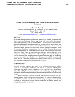
  • 1. Dynamic Analysis of an Offshore Wind Turbine: Wind-Waves Nonlinear Interaction Manenti S., Petrini F. University of Rome Sapienza, via Eudossiana, 18 – 00184 Rome (Italy) Phone: +39 06 44 585 265 Fax: +39 06 48 848 52 e-mail: sauro.manenti@uniroma1.it - francesco.petrini@uniroma1.it ABSTRACT An offshore wind turbine can be considered as a relatively complex structural system since several environmental factors (e.g. wind and waves) affect its dynamic behavior by generating both an active load and a resistant force to the structure’s deformation induced by simultaneous actions. Besides the stochastic nature, also their mutual interaction should be considered as nonlinear phenomena could be crucial for optimal and cost-effective design. Another element of complexity lies in the presence of different parts, each one with its peculiar features, whose mutual interaction determines the overall dynamic response to non-stationary environmental and service loads. These are the reasons why a proper and safe approach to the analysis and design of offshore wind turbines requires a suitable technique for carrying out a structural and performances decomposition along with the adoption of advanced computation tools. In this work a finite element model for coupled wind- waves analysis is presented and the results of the dynamic behavior of a monopile- type support structure for offshore wind turbine are shown. INTRODUCTION Owing to the major regularity and power of the wind forcing, open-sea turbines could be an advantageous alternative with respect to analogous inland plants; furthermore they could become competitive with respect to other conventional, exhaustible and high environmental impact sources of energy if a proper design approach is established assuring a good compromise between safety and costs related aspects. Anyway boundary conditions (i.e. loads and constraints) are highly time- and space-dependent, along with mechanical properties of the materials that are subject to significant variation over the structural life owing to fatigue, marine growth, corrosion etc. Furthermore different configurations must be handled, passing from complete functionality to rotor stop. 2014 Earth and Space 2010: Engineering, Science, Construction, and Operations in Challenging Environments © 2010 ASCE
  • 2. As a consequence these structures can be defined “complex” and this requires a critical revision of the design procedure according to a systemic approach (Bontempi, 2008b), i.e. a systemic decomposition of the relevant elements both physical (e.g. the constituting parts) and environmental related (i.e. identification of the structural loads and constraints). Different aspects and various performances under several load conditions have to be investigated for this type of structures. Referring to all possible system configurations that can be assumed by the blades and then by the rotor, one need explicitly: 1. to ensure that the components are designed for the extreme loads allowing a fair survivability; 2. to assure that the fatigue life of the components is guaranteed for the service life; 3. to define component stiffness with respect to vibrations and critical deflections in a way that the behavior of the turbine can keep under control by a careful matching of stiffness. In this context an important task concerns the proper definition of nonlinear interaction between the forcings (e.g. wind and wave) that can influence significantly the numerical prediction of the dynamic response and, consequently, the durability and the cost-effectiveness of the turbine (OWTES, 2003). Since an offshore wind turbine is generally planned for installation in intermediate depth water (with respect to a representative design wave length), its dynamic characteristics are fairly different from an offshore platform for oil industry: the latter usually has a design natural frequency higher than the wave excitation, while the former is wedged between the wind and wave frequency; so in the last case nonlinear interaction between the environmental forcings should be properly considered during the design phase as it can led to a beneficial aerodynamic damping by lowering the structural stiffness of the turbine’s support: this would lead to both an increase fatigue life and reduce the cost of the support. Relevant codes and standards (BSH, DNV, GL, IEC) provides an accurate description of the analytical methods for estimating the random action by wind and waves separately; anyway nonlinear interaction phenomena still requires an in depth and careful investigation with the aim to give reliable estimate of the loads: such an aspect could play a crucial role in the calculation procedure of economical and safe offshore wind turbines. This work is part and continues an early study on the modeling and design of offshore wind turbines (Bontempi, 2009); its approach follows structural and performances decomposition in order to organize the qualitative and quantitative assessment in various sub-problems, which can be faced by sub-models of different complexity both for structural behavior and load scenarios. In the present work the dynamic analysis of a turbine and its monopile support structure in the frequency domain is carried out by means of the ANSYS finite element model. Initially the loading induced by wind and random waves acting separately is considered; subsequently the nonlinear effects by their mutual 2015 Earth and Space 2010: Engineering, Science, Construction, and Operations in Challenging Environments © 2010 ASCE
  • 3. interaction are accounted with the aim of pointing out the implication on the design procedure. The outline of the paper is as follow: • the main features of both the ANSYS finite element and the analytical models for the wind and wave random forcing are illustrated; • the results of the analyses carried out are discussed by pointing out the nonlinear effect induced by wind-waves interaction; • final conclusions concerning the study are then illustrated at the end of the paper. MODEL DESCRIPTION In the present work a 5MW 3-bladed offshore wind turbine with monopile-type support is considered for carrying out the coupled wind-wave spectral analysis: it represents a structure of interest for possible planning of an offshore wind farm in the Mediterranean Sea near the south-eastern cost of Italy. Tab. 1. Main geometrical characteristics of the structure. Monopile type support Z Y X Aerodynamic Fluid- dynamic Geotechnical Foundation Submerged Emergent d lfound H mud line Z Y X Z Y X Aerodynamic Fluid- dynamic Geotechnical Foundation Submerged Emergent d lfound H mud line H = 100m d=35m lfound=40m D =5m tw=0.05m Dfound=6m D = diameter of the tubular tower; tw = thickness of the tower tubular member; The main geometrical characteristics are summarized in Tab. 1: a Vestas-V90 turbine with rotor diameter of 100m; the hub height is positioned 100m above mean sea level (m.s.l.); the tower, with a steel tubular section, has a diameter of 5m with a 2016 Earth and Space 2010: Engineering, Science, Construction, and Operations in Challenging Environments © 2010 ASCE
  • 4. thickness of 50mm; water depth is 35m. At this stage of investigation the effect of foundation medium has been neglected and the lower node of the pile is assumed fixed at the sea bottom. Even if such an hypothesis looks like far from the actual behavior of the structure, it has been possible, during an early phase, to check the numerical model by comparing the numerical results with the analytical solution for an equivalent one-degree of freedom body. Additional investigations have to be carried out for introducing the effect of marine soil on the dynamic response of the wind turbine and the support (here after the structure). The monopile support has been selected as it appear economically convenient for intermediate water depth purposes: according to the DNV (2004) classification its range of application is around 25m water depth and it would be a possible design solution for planning an offshore wind farm in the southern Adriatic Sea. Moreover it is a relatively simple support structure and this allow to reduce the uncertainties related to the wave-induced loads estimation on submerged sloping members (Chakrabarti et al., 1975). In this work the analysis is performed by considering typical wind and waves forcing with relatively small recurrence period (i.e. exercise load condition) that could be crucial for fatigue-induced long term damage; an early investigation based on extreme events for monopile-type and other support structure has been yet carried out in Bontempi (2008a). In the following subsections a description of the main features relevant to the finite element model is provided; then the analytical models for the estimate of wind and waves random loads are shown separately. z y x,x’ z’ y’ W ater level (medium) Mud line Waves Medium wind Current P (t)vP (t)wP (t)uP Turbulent wind Vm(zP) P Water level (medium) Mud line Hub level R H h vw(z’) Vcur(z’) z y z y x,x’ z’ y’ x,x’ z’ y’ W ater level (medium) Mud line Waves Medium wind Current P (t)vP (t)wP (t)uP P (t)vP (t)wP (t)uP Turbulent wind Vm(zP) P Water level (medium) Mud line Hub level R H h vw(z’) Vcur(z’) Fig. 1 Problem sketch and actions configuration. 2017 Earth and Space 2010: Engineering, Science, Construction, and Operations in Challenging Environments © 2010 ASCE
  • 5. Model Features. The finite element model is realized with the ANSYS finite element code by adopting beam elements (BEAM4) for simulating the tower, while the blades and nacelle have been represented by a concentrated mass Mtop on the tower top by means of MASS21 element on which is applied the random horizontal force caused by the wind trust. The tower base is assumed to be fixed for the reasons explained above. A suitable discretization of the exposed structure is carried out for load application; at each node a spectral force is specified which corresponds to the effect of random waves (for nodes below the mean sea level) or wind excitation acting on the corresponding area of pertinence. Calculation of the force spectrum for both environmental factors has been carried out by applying the analytical models described in the following. Tab. 2 summarizes the principal mechanical parameters for calculation of the random loads: E is the elastic modulus, ρ is the density, cD is the drag coefficient, cM is the hydrodynamic added mass coefficient and cL is the lift coefficient. Tab. 2. Summary of the most relevant model parameters. Vm10 [m/s] 14.5 Esteel [kg/m2 ] 2.059E+11 Eblade [kg/m2 ] 3.100E+20 ρsteel [kg/m3 ] 7.980E+3 ρwater [kg/m3 ] 1.024E+3 cD hydr 1.05 cM hydr 1.00 cD tow 0.50 cD blade 0.15 cL blade 1.00 Mtop [kg] 1.1E+5 Wave Forcing. In the present work a Pierson-Moskowitz wave spectrum (for fully developed sea condition) is adopted for dynamic analysis of the support structure for the offshore wind turbine (Kamphuis, 2000): 4 4 4 5 2 74.0 , 4 5 ,0081.0 exp2)( ⎟ ⎠ ⎞ ⎜ ⎝ ⎛ === ⎥ ⎥ ⎦ ⎤ ⎢ ⎢ ⎣ ⎡ ⎟⎟ ⎠ ⎞ ⎜⎜ ⎝ ⎛ −⋅ ⋅ = V g g S PM pPMPM p PM PM β ωβα ω ω β ω α πωηη (1) with ω =2π/T=2π f angular frequency, ωp spectral peak angular frequency, η(t) local free surface elevation with respect to the mean sea level (m.s.l.), V intensity of characteristic wind speed at the reference height of 19.5m above m.s.l. (see Eq. (12) for variation of the mean wind sped over the height). 2018 Earth and Space 2010: Engineering, Science, Construction, and Operations in Challenging Environments © 2010 ASCE
  • 6. According to the linear wave theory and making use of complex algebra the time evolution of the free surface elevation η and of the horizontal components of the water particles velocity x& and acceleration x&& for each spectral wave component of angular frequency ω are respectively: ),(),( )( sinh cosh ),( )exp()( 0 tzxitzx t kd kz tzx tiat &&& & ω ηω ωη −= ⋅= −= ; (2) By applying the Fourier transform and its conjugate to the variable x& , the spectrum of the horizontal velocity component of the water particles can be obtained: )( sinh cosh ),( 2 ωωω ηηS kd kz zS xx ⋅⎟ ⎠ ⎞ ⎜ ⎝ ⎛ =&& ; (3) where from Sηη is defined by Eq. (1); the standard deviation of the water particles velocity component is then given by: ∫∫ ∞∞ ⋅⎟ ⎠ ⎞ ⎜ ⎝ ⎛ == 0 2 0 2 )( sinh cosh ),()( ωωωωωσ ηη dS kd kz dzSz xxx &&& . (4) In this work the Morison et al. (1950) empirical formula for evaluating the force induced by a regular surface non-breaking wave on a slender and partially submerged vertical cylinder is adopted. d |z| z x d+z dF(z,t)dz A A Sect. A-A D tw d z x dF(z,t)dz A A Sect AA D tw Fig. 2 Specific force induced by regular wave on a partially submerged cylinder. 2019 Earth and Space 2010: Engineering, Science, Construction, and Operations in Challenging Environments © 2010 ASCE
  • 7. According to the scheme in Fig. 2 the force per unit length on the column is: ),(),(),(),( tzxtzxCtzxCtzdF DI &&&& += (5) which is the sum of two distinct contributions: i) inertial force, also called virtual mass force, that is proportional to the horizontal component of the water particle acceleration; ii) drag force, proportional to the square of the water particle horizontal velocity. The expression (5) implies that the axis of the cylinder is orthogonal to the direction of wave advance; the horizontal components of both water particle velocity and acceleration are evaluated at the column axis as if it was absent by adopting the linear wave theory (Dean & Dalrymple, 1991). The inertia and drag coefficients in Eq. (5) has the following expression for a cylinder having circular section of diameter D: DcCCCA D cC WDDAMWWMI ρρ π ρ 2 1 4 2 =+=+= . (6) The inertia coefficient is made up of two contribution: the former is due to hydrodynamic mass and the latter pertains the variation of the pressure gradient within the accelerating fluid. The added mass coefficient cM is tabulated for the geometries of technical interest (Hooft, 1978); the drag coefficient cD is a function of the Reynolds number. Moreover both coefficients depends also on the Keulegan-Carpenter number defined as: DTxKC max &= , (7) with maxx& the maximum horizontal component of the water-particle velocity, T is the wave period and D is the cylinder diameter (Chakrabarti et al., 1976). Assuming that the velocity of the fluid particles is a Gaussian process with zero mean it is possible to eliminate nonlinearity from the drag term in Eq. (11)5 and write the linearized Morison force per unit length as follows: ),(),( 8 ),(),( tzxtzCtzxCtzdF xDI &&& &σ π += , (8) being x&σ the standard deviation of the water-particle velocity component in x direction given by Eq. (4). The Eq. (5) holds for a vertical cylinder (not necessary circular); when dealing with certain structures containing some members forming an angle with the vertical direction, such as steel lattice type, there is no general agreement on how the Morison Eq. should be extended to deal with. A method has been proposed in Chakrabarti et al. (1975) that generalize the formulation given in (5) for a vertical cylinder. 2020 Earth and Space 2010: Engineering, Science, Construction, and Operations in Challenging Environments © 2010 ASCE
  • 8. The force dF acting per unit length on the wet part of the support structure associated to a random sea state with spectral energy density Sηη as defined by Eq. (1) can be obtained by considering the expression of η, xx &&& and in (8) and substituting into Eq. (5): )()()cosh( 8 )cosh( sinh ),( tzkzCkziC kd tzF xDI ησ π ω ω ⎥ ⎦ ⎤ ⎢ ⎣ ⎡ +−= & , (9) being k=2π/L the wave number and L the wave length; note that the complex response method is adopted for representation of the harmonic variables (i denotes the imaginary unit). By making the Fourier transform of such an expression the force spectrum is obtained as a function of the wave energy spectral density: [ ] )()()cosh( 8 )cosh( )sinh( ),( 2 2 2 ωσ π ω ω ω ηηSzkzCkzC kd zS xDIFF ⋅ ⎪⎭ ⎪ ⎬ ⎫ ⎪⎩ ⎪ ⎨ ⎧ ⎥ ⎦ ⎤ ⎢ ⎣ ⎡ +⎥ ⎦ ⎤ ⎢ ⎣ ⎡ = & , (10) where the expression between braces in Eq. (10) is the force transfer function. Wind Forcing. Concerning the wind modeling for computing the aerodynamic actions, a Cartesian three-dimensional coordinate system (x,y,z), with origin at water level and the z-axis oriented upward is adopted as shown in Fig. 1. Focusing on a short time period analysis the three components of the wind velocity field Vx(j), Vy(j), Vz(j) at each spatial point j (the variation with time is omitted for simplicity) can be expressed as the sum of an averaged (time-invariant) value Vm and the turbulent components u(j), v(j), w(j) with zero mean. Assuming that Vm is non zero only in x direction, the three components of the total velocity are given by: )()();()();()()( jwjVjvjVjujVjV zymx ==+= . (11) The mean velocity Vm(j) can be determined by a database of values recorded at or near the site, and evaluated as the record average over a proper time interval (e.g. 10 minutes). The variation of the mean velocity Vm with z over an horizontal surface of homogeneous roughness can be described, as usual, by an exponential law: α ⎟⎟ ⎠ ⎞ ⎜⎜ ⎝ ⎛ = hub hubm z z VzV )( . (12) In this expressions, Vhub is the reference wind velocity at the rotor elevation zhub, α=0.14 for extreme wind conditions; Vhub it is usually obtained as the mean of the wind velocity on a 10 minutes time period V10. 2021 Earth and Space 2010: Engineering, Science, Construction, and Operations in Challenging Environments © 2010 ASCE
  • 9. The turbulent components of the wind velocity are modeled as zero-mean Gaussian ergodic independent processes; by adopting an Eulerian description and a discretization of the spatial domain in N points representing the locations where the wind acts on the structure, each Gaussian process is completely characterized by the power spectral density matrix [S]i, (i = u, v, w). The diagonal terms Sijij(n, z) (i = u, v, w and j = 1,2,…,N) of [S]i are given by the normalized half-side von Karman’s power spectral density (Solari and Piccardo, 2001): [ ] 6522 8701 4 / i i ijij (z)n. n σ (n,z)nS i + = , (13) where n is the current frequency (in Hz), z is the height (in m), σi 2 is the variance of the velocity fluctuations, given by (Solari and Piccardo, 2001): ( )[ ] 2 0 2 751logarctan116 *i u.)(zg.-σ += , (14) with z0 is the roughness length, u* is the friction or shear velocity (in m/s), given by: (0.006)1/2 Vm(z=10), while ni(z) is a non-dimensional height dependent frequency given by: )( )( )( zV znL zn m i i = . (15) The integral scale Li(z) of the turbulent component can be derived respectively for i = u, v, w according to the procedure given in ESDU (2001). The out of diagonal terms Sijik(n, z) (k = 1,2,…,N) of [S]i are given by: ))(exp()()()( nfnSnSnS jkikikijijijik −= , (15) being: ( ))()(2 )( )( 22 kmjm kjz jk zVzV zzCn nf + − = π , (16) where Cz represents the decay coefficient, that is inversely proportional to the spatial correlation of the process. By considering a drag and lift force produced by undisturbed wind velocity acting on exposed turbine parts, the proposed model allows to estimate the force spectrum at the j-point of the structure. When considering mobile structural parts such as the rotor blades, relative wind speed (in a frame of reference moving with the blade) should be assumed for drag and lift force computation. For more details about such topics refers to Bontempi et al. (2008a). 2022 Earth and Space 2010: Engineering, Science, Construction, and Operations in Challenging Environments © 2010 ASCE
  • 10. DISCUSSION OF RESULTS In the following results for the analyses carried out are discussed: first wave and wind forcing are treated separately and then their mutual interaction is investigated; the values adopted for the most relevant model parameters are summarized in Tab. 2. Fig. 3 shows the input spectra to the finite element model: both have been plotted for a mean wind speed of 14.5m/s at 10m elevation above m.s.l. directed in x- direction and correspond to the parametric formulation given in previous Sections. 1.0E-01 1.0E+01 1.0E+03 1.0E+05 1.0E+07 1.0E+09 1.0E+11 1.E-04 1.E-02 1.E+00 1.E+02 1.E+04 freq [Hz] Forcespectra[N 2 /Hz] Wind Wave Fig. 3 Wind and wave force energy density spectra. Wave Forcing. Fig. 4 shows the results for the case of wave forcing acting alone on the structure. 1.0E-03 1.0E-02 1.0E-01 1.0E+00 1.0E+01 1.E-04 1.E-03 1.E-02 1.E-01 1.E+00 freq [Hz] Responsespectra[m 2 /Hz] X direction Fig. 4 Response spectra for wave forcing only. 2023 Earth and Space 2010: Engineering, Science, Construction, and Operations in Challenging Environments © 2010 ASCE
  • 11. The frequency of the first relative peak corresponds to the peak frequency of the wave force spectrum (about 0.1Hz); the maximum of the structural response occurs however at about 0.2Hz which is very close to the first vibration mode of the structure. Wind Forcing. Fig. 5 shows the results for the case of wind forcing acting alone on the structure. 1.0E-03 1.0E-02 1.0E-01 1.0E+00 1.0E+01 1.E-04 1.E-03 1.E-02 1.E-01 1.E+00 freq [Hz] Responsespectra[m 2 /Hz] X direction Y direction Fig. 5 Response spectra for wind forcing only. In this case the structural response in y-direction (i.e. orthogonal with respect to the mean wind direction) is non-zero since the two speed turbulent components are correlated as explained above. The spectral response is however higher along the x-direction as expected since the wind energy distribution is greater. In both cases a maximum peak appear for the peak frequency of the wind spectrum and close to the first mode frequency of the structure. Combined Wind-Wave. When considering the effects of both wind and wave on the structure, the increasing roughness length of the sea surface owing to the presence of propagating waves has been modeled according to an iterative process following Holmes 2001. Fig. 6 shows calculated response spectra in each coordinate horizontal direction. While along the y-axis the results are not affected by the presence of waves propagating in the orthogonal direction, when considering the x-oriented response spectrum it shows, in addition to the case of wind only (Fig. 5), the characteristic relative maximum at the wave peak frequency (about 1Hz); furthermore, at the structure’s natural frequency (i.e. 0.2Hz) the curve is above the value of 1.0m2 /Hz but it is not exactly the summation of those related to the wind and the wave alone (Fig. 4 and 5). 2024 Earth and Space 2010: Engineering, Science, Construction, and Operations in Challenging Environments © 2010 ASCE
  • 12. 1.0E-03 1.0E-02 1.0E-01 1.0E+00 1.0E+01 1.E-04 1.E-03 1.E-02 1.E-01 1.E+00 freq [Hz] Responsespectra[m2/Hz] X direction Y direction Fig. 6 Response spectra for combined wind-wave forcing. The phenomenon described above is the result of a destructive interference between wind and wave forcings: the resultant energy density of the response spectra at the structure’s natural frequency is less than the sum of the corresponding values related to the wind and wave acting separately. CONCLUSIONS In this work a finite element model for the dynamic analysis of a monopile-type support structure for offshore wind turbine has been presented. The structural response in the frequency domain has been analyzed for both wind and wave spectral forcings obtained starting from a characteristic wind velocity which is representative of the exercise condition to be adopted for fatigue-damage analysis. These forcings have been considering as acting separately in the first phase, and then their mutual interaction has been simulated. Obtained results have shown that the response spectrum at the natural frequency of the structure exhibit a destructive interference between wind and wave forcings acting simultaneously. As a consequence, nonlinear interaction should be considered in the design phase of a safe and cost-effective offshore wind turbine as the actual load on the structure could be lower than that extrapolated from the linear superposition of the effects produced by the single forcings acting separately. ACKNOWLEDGEMENTS The present work has been developed within the research project “SICUREZZA ED AFFIDABILITA' DEI SISTEMI DELL'INGEGNERIA CIVILE: IL CASO DELLE TURBINE EOLICHE OFFSHORE", C26A08EFYR, financed by University of Rome La Sapienza Fruitful discussions with Prof. Franco Bontempi are also acknowledged 2025 Earth and Space 2010: Engineering, Science, Construction, and Operations in Challenging Environments © 2010 ASCE
  • 13. REFERENCES APAT. 2006 Italian wave atlas. Bontempi F., Manenti S., Gkoumas K.. 2009. Basis of design for offshore wind turbines. Proc. Of Seminar OWEMES May 21-23 2009, Brindisi (Italy). Bontempi F., Li H., Petrini F., Manenti S.. (a) 2008. Numerical modelling for the analysis and design of offshore wind turbines, ASEM’08 Int. Conf. 26-28 May 2008, Jeju (Korea). Bontempi, F., Gkoumas, K. and Arangio, S.. (b) 2008. Systemic approach for the maintenance of complex structural systems. Structure and infrastructure engineering, vol. 4; pp. 77-94. BSH. (2007) Design of Offshore Wind Turbines, 20 December 2007. Chakrabarti S.K., Wolbert A.L., Tam W.A.. 1976. Wave forces on vertical circular cylinder. Proc. ASCE (waterways, Harbours and Coastal Eng. Div.) 102. Chakrabarti S.K., Tam W.A., Wolbert A.L.. 1975. Wave forces on a randomly oriented tube. OTC 2190 Proc. Offshore Technology Conf. Huston. Davenport, A.G.. 1998. Probabilistic methods in wind engineering for long span bridges, Proc. of the Int. Symp. on Advances in Bridge Aerodynamics, May 1998, Copenhagen, Denmark. Dean R.G., Dalrymple R.A.. 1991. Water wave mechanics for engineers and scientists. The Advanced Series on Ocean Engineering. World scientific, Vol. 2. ESDU. 2001. Report N. 86010: Characteristic of atmospheric turbulence near the ground. Part III: variations in space and time for strong winds (neutral atmosphere). Available at www.esdu.com. DNV-OS-J101. (2004) Offshore standards-Design of offshore wind turbine structures. GL. 2005 Guidelines for certification of offshore wind turbines. Holmes, J.D., 2001. Wind loading of structures, Spoon Press. Hooft J.C.. 1978. Advanced dynamics of marine structures. New York: John Wiley & Sons. IEC 61400-3. (2005) Wind Turbines - Part 3: Design Requirements for Offshore Wind Turbines, Committee Draft, December 2005. Kamphuis J.W.. 2000. Introduction to coastal engineering and management. The Advanced Series on Ocean Engineering. World scientific, Vol. 16. Morison J.R., O’Brien M.P., Johnson J.W., Schaaf S.A.. 1950. The force exerted by surface waves on piles. Petrol. Trans. AIME 189. OWTES-Design Methods for Offshore Wind Turbines at Exposed Sites. 2003. Hydrodynamic loading on offshore wind turbines. TUDelft Editor. Solari G. and Piccardo G.. 2001. Probabilistic 3-D turbulence modelling for gust buffeting of structures, Probabilistic Engineering Mechanics, (16), 73–86. Zienkiewicz O.C., Lewis R.W., Stagg K.G. et al.. 1978. Numerical methods in offshore engineering. J. Wiley & Sons- Interscience Publication. 2026 Earth and Space 2010: Engineering, Science, Construction, and Operations in Challenging Environments © 2010 ASCE