
Recommandé
Contenu connexe
Tendances
Tendances (20)
En vedette
En vedette (20)
Similaire à Gajendra rathore
Similaire à Gajendra rathore (20)
Dernier
Dernier (20)
Gajendra rathore
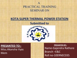
- 1. A PRACTICAL TRAINING SEMINAR ON KOTA SUPER THERMAL POWER STATION Submitted to PRESANTED TO:- Miss.Akansha Vyas Mem PRESANTED BY:- Name-Gajendra Rathore Branch –E&C Roll no-10ERNEC035
- 2. WELCOME
- 3. CONTENTS 1. INTRODUCTION 2. COAL HANDLING PLANT 3. ASH HANDLING PLANT 4. ESP 5. BOILER 6. STREAM TURBINE 7. TURBO GENERATOR 8. WATER TREATMENT PLANT 9. TRANSFORMER 10. CONTROL ROOM
- 4. LOCATION Ideally on the left bank of Chambal River at Up Stream of Kota Barrage The 220 KV GSS is within ½ Kms. LAND Land measuring approx. 250 hectares was required for the project in 1976 COAL Coal India limited supply coal from its coal producing subsidiaries BCCL, SECL & ECL through railway wagons WATER The source of water for power station is reservoir formed by Kota Barrage on the Chambal River
- 5. STAGE I 2x110 MW STAGE Il 2x210 MW STAGE Ill 1x210 MW STAGE IV 1x195 MW STAGE I 1x195 MW Net Power Generation = 1240 MW 3
- 7. POWER SYSTEM COMPONENTS • , 220 kV Power Plant Generation Residential Customer Commercial/ Industrial Customer Residential Customer Distribution Pole Urban Customers Primary Distribution 66 kV Transmission Distribution Transformer (11/0.415 kV) Secondary Grid (66/11 kV) Primary Grid (220/66 kV) Secondary Distribution Underground Cable To Other 66Kv Substations Primary Transmission(132/220/400/765KV) Secondary Transmission(66/132KV) CBX’mer (11/220kV)Sending end SS Bus-bar Bus-bar Steel Tower CB V V Nagar GCET
- 8. 2. COAL HANDLING PLANT • This plant have 3 parts... A. Wagon unloading system. B. Conveying belt system. C. Crushing system.
- 9. IMAGE OF COAL HANDLING PLANT
- 10. COAL LOADED BY TRAIN • SOURCE OF COAL : COAL INDIA LTD. BCCL,SECL & ECL • MEANS OF TRANSPORTATION: - RAILWAY WAGONS • TYPE OF COAL : BITUMINOUS TAKEN TO COAL MILLS THROUGH CONVEYOR BELTS. CRUSHED INTO POWDERED FORM IN COAL MILLS. WITH THE HELP OF PRIMARY AIR FANS IT IS TAKEN TO BOILER. • COAL HANDLING PLANTCOAL HANDLING PLANT
- 11. A. Wagon unloading system • Unload the coal from wagon to hopper. • Hopper allows to pass coal pieces ≤ 200mm • From hopper coal fall on vibrator which is supported by roller.
- 12. C.Conveying system • Belt are used to convey coal from coal handling plant to furnance. • Specification:- – Belt width : 1400mm – Speed : 2.2m/sec – Total install power : 360kw – Capacity : 1350/750 ton/hr – No. of conveyor: 38
- 14. 5. BOILER with FURNANCE
- 15. four part is connected with the boiler & furnance section 1. Water treatment plant. 2. Ash handling plant. 3. ESP(Chimeny) 4. Turbine section.
- 16. • SOURCE OF WATER :- CHAMBAL RIVER W.T.P. DIVIDED IN TWO PARTS :- FILTERATION WATER PLANT DEMINERALISED WATER PLANT
- 17. CHART OF W.T.P
- 18. IMAGE OF D.M. WATER PLANT
- 19. ASH HANDLING PLANT ASH HANDLING PLANT
- 20. ASH HANDLING PLANT This plant can be divided into three sub plants as follows :- 1)Fuel and Ash Plant:- 2)Air and Gas Plant:- 3) Ash Disposal and & Dust Collection Plant:-
- 23. 6.TURBINE
- 24. Designed for continuous operation at the rated output. Directly coupled with steam turbine, rotated at high speed of 3000 RPM. Two major parts:- (i) Stator (ii) Rotor Major parts of stator are (i) Stator frame. (ii)Stator core. (iii)Stator bars. (iv)Stator windings.
- 25. Working of turbine & generator:- STEAM TURBINE MECHANICAL ENERGY GENERATOR ELECTRICAL ENERGY
- 26. 8.Cooling System • In KSTPS hydrogen cooling system is employed for generator cooling. • Hydrogen is used because of its superior cooling properties & low density. • Thermal conductivity of H2 7.3 times of air. • Seal oil system are used in turbine for less friction in bearing. • Water cooling also used for any kind of fire.
- 27. 10. Transformer
- 28. Various Transformers In KSTPS – Generating Transformer – Unit Auxiliary Transformer (U.A.T.) – Station Transformer (S.T.) – Exciting Transformer – Earthing Transformer – Instrument Transformer
- 31. 11.SWITCH YARD
- 32. CIRUCIT BREKER Minimum oil circuit breaker Sf6 circuit breaker
- 33. MAIN CONTROL ROOM • This room is control every plant… 1) Fan control desk. 2) Fuel control desk. 3) Steam & water desk. 4) Turbine desk. 5) Generator control panel.
Notes de l'éditeur
- Specification of U.A.T.