SlideShare une entreprise Scribd logo
1  sur  6
Télécharger pour lire hors ligne
International Journal of Modern Engineering Research (IJMER)
www.ijmer.com Vol. 3, Issue. 4, Jul - Aug. 2013 pp-2275-2280 ISSN: 2249-6645
www.ijmer.com 2275 | Page
Satish Choudhary1
, Dr. Bhupendra Gupta2
, Dr. Mukesh pandey3
Dr. Prashant Baredar4
1
Student, Master of Engineering, Heat Power, JEC, Jabalpur
2
Assistant Professor, Jabalpur Engineering College, Jabalpur, India
3
Professor, School of Energy and Environment, UIT, RGPV Bhopal, India
4
Associate Professor, MANIT, Bhopal, India
ABSTRACT: The air and water flow distribution are experimentally studied for a round header – flat tube geometry
simulating a parallel flow heat exchanger. The number of branch flat tube is 25. The effects of tube outlet direction, tube
protrusion depth and quality are investigated. The flow at the header inlet is identified as annular. For the upward flow
configuration, the water flow distribution is significantly affected by the tube protrusion depth. For flush-mounted
configuration, most of the water flows through frontal part of the header. As the protrusion depth increases, minimum water
is forced to the rear part of the header. Possible explanations are provided based on the flow visualization results.
KEYWORDS: Flow distribution; Parallel flow heat exchanger; Air and water flow measurement; Reverse upward flow;
Two-phase; Experimental approach.
I. INTRODUCTION
Two-phase flow distribution of Air and water was experimentally investigated in a parallel flow heat exchanger
comprised of two horizontal headers and twenty five vertical channels. Most of the flow in the header inlet was identified as
stratified flow. The effect of tube protrusion depth was also investigated. It was observed that, For upward flow, significant
portion of liquid was forced to rear part of the header. The effect of quality and protrusion depth on the liquid distribution
was also investigated.
Aluminum based heat exchangers consist of flat tubes of 5 mm hydraulic diameter. For the vertical header configuration,
most of the liquid flowed through the frontal part of the header, and the effect of the inlet pipe direction was not significant.
For a horizontal header, the flow distribution was highly dependent on the inlet pipe direction, and better distribution was
obtained for the parallel configuration.
II. EXPERIMENTAL SETUP
The Experimental Setup used for this study is shown in Figure 2.1. The hydraulic diameter of the present flat tube is
5 mm, and the flow cross sectional area is 25 mm2
. The test section consists of the 16 mm internal Diameter round upper and
lower headers, which are 90 cm apart, and 25 flat tubes inserted at 3 mm pitches. This configuration was chosen to simulate
the actual parallel flow heat exchanger. Twenty five flat holes were machined at the bottom for insertion of flat tubes. An
aluminum plate, which had matching flat holes, was installed underneath the header as illustrated in Fig. 2.1Flat tubes were
secured, and the protrusion depth was adjusted using O-rings between the header and the aluminum plate. Transition blocks
were installed in the test section to connect the flat tubes and the 5.0 mm ID round tubes. The round tubes served as flow
measurement lines. At the inlet of the header, 1.0 m long aluminum tube having the same internal diameter as the header was
attached. The tube served as a flow development section.
Figure 2.1: Experimental setup Figure 2.2: Water flow meter
Figure 2.3: Flow distribution system Figure 2.4: Electrical control panel
Effect on Efficiency of Two-phase Flow Distribution in a
Parallel Flow Heat Exchanger with Reverse Upward Flow
International Journal of Modern Engineering Research (IJMER)
www.ijmer.com Vol. 3, Issue. 4, Jul - Aug. 2013 pp-2275-2280 ISSN: 2249-6645
www.ijmer.com 2276 | Page
Table 2.1: Components used in Setup
Sr.No. Name of component Specification
1 Air blower 15 amp.220 v ac
2 Water heater 1000 w
3 Water pump 65w
4 Water flow meter ½ inch Diameter
5 Air flow meter ½ inch Diameter
6 Air and water Separator 4 inch Diameter
7 Flexible pipe 15 mm Diameter
8 Thirteen valve ½ inch Diameter
9 Vertical square aluminum pipe Thickness 1.5mm
10 Vertical circular aluminum pipe Thickness 1.5mm
11 Inlet tank 40Liters
12 Outlet tank 25 Liters
13 Electrical control panel 15 amp.
III. METHODOLOGY
III.1. UPWARD FLOW: An upward flow was observed at the header inlet. The liquid motion in the lower header was
unstable and intermittent. Liquid was supplied into the channels by electrical water pump. The Air and water distribution is
generally reverse to the liquid distribution. The flow visualization results that the liquid is forced to frontal part of the header
as the quality increases. The liquid is forced to frontal part of the header as the quality decreases, yielding better liquid
distribution. The explanation at lower quality, more liquid is supplied into the header, supplying more liquid to frontal part
may be provided. The annular flow using air and water revealed that more water was forced to frontal part of the header at a
higher quality. The reason was attributed to the increased water film thickness at the upper part of the header at increased
quality. The part of the incoming water impinges at the first protrusion, separates at the top, reattaches at the bottom of the
header due to the action of gravity. The separated water, along with the water from lower part of the header, is forced to the
rear end of the header, and starts to fill in the tubes from backward.
IV. RESULT AND DISCUSSION
IV.1. Reverse upward flow: In reverse upward flow, the air and water are flow in the direction of upward and after that
air and water are achieve in separator. Temperature at inlet is 50 °C., Temperature at outlet is 45.8 °C.
Time taken during reading = 10 sec.
Temperature at inlet =50 °C
Temperature at outlet =45.8 °C
H= witch insert in pipe
D= 16mm diameter of pipe
Table 4.1.1: Air flow in different h/d and Reverse upward flow
Sr.
No.
Channel
no.
Air
flow
(m3
/sec)
At h/d
= 0/16
=0.0
Air
flow
(m3
/sec)
At h/d
= 4/16
=0.25
Air
flow
(m3
/sec)
At h/d
=8/16
=0.5
1 1-5 0.5 1.5 1.5
2 6-10 1.2 1.4 1.2
3 11-15 1.3 1.2 1.0
4 16-20 0.5 0.5 1.0
5 21-25 0.2 0 0.0
Fig. 4.1.1: Air flow in different h/d and Reverse upward flow
International Journal of Modern Engineering Research (IJMER)
www.ijmer.com Vol. 3, Issue. 4, Jul - Aug. 2013 pp-2275-2280 ISSN: 2249-6645
www.ijmer.com 2277 | Page
Table 4.1.2 Water flow in different h/d and Reverse upward flow
Sr. No. Channel no. Water flow (L/ sec) At
h/d = 0/16 =0.0
Water flow (L/ sec) At
h/d = 4/16 =0.25
Water flow (L/ sec)
At h/d = 8/16
=0.5
1 1-5 2.0 0.5 0.4
2 6-10 0.5 0.4 0.5
3 11-15 0.4 0.4 0.5
4 16-20 1.0 0.5 1.4
5 21-25 2.2 1.5 2.3
Figure 4.1.2: Water flow in different h/d and Reverse upward flow
Efficiency:
Temperature at inlet =50 °C
Temperature at outlet =45.8 °C
ή= (Temperature at inlet - Temperature at outlet) / Temperature at inlet
= (50-45.8)/50 =08.40%
IV.2. REVERSE UPWARD FLOW: In reverse upward flow, the air and water are flow in the direction of upward and
after that air and water are achieve in separator. Temperature at inlet is 60 °C., Temperature at outlet is 53.6 °C.
Time taken during reading = 10 sec.
Temperature at inlet =60 °C.
Temperature at outlet =53.6 °C
H= witch insert in pipe
D= 16 mm diameter of pipe
Table 4.2.1: Air flow in different h/d and Reverse upward flow
Sr. No. Channel no. Air flow (m3
/sec)
At h/d = 0/16
=0.0
Air flow (m3
/sec)
At h/d = 4/16
=0.25
Air flow (m3
/sec)
At h/d =8/16
=0.5
1 1-5 0.6 1.6 1.5
2 6-10 1.3 1.5 1.3
3 11-15 1.4 1.3 1.2
4 16-20 0.7 0.4 1.1
5 21-25 0.2 0.3 0.1
Figure 4.2.1: Air flow in different h/d and Reverse upward flow
International Journal of Modern Engineering Research (IJMER)
www.ijmer.com Vol. 3, Issue. 4, Jul - Aug. 2013 pp-2275-2280 ISSN: 2249-6645
www.ijmer.com 2278 | Page
Table 4.2.2: Water flow in different h/d and Reverse upward flow
Sr. No. Channel no. Water flow (L/ sec) At
h/d = 0/16 =0.0
Water flow (L/ sec) At
h/d = 4/16 =0.25
Water flow (L/ sec)
At h/d = 8/16
=0.5
1 1-5 2.1 0.5 0.4
2 6-10 0.6 0.4 0.5
3 11-15 0.5 0.4 0.6
4 16-20 1.2 0.5 0.9
5 21-25 2.4 0.9 1.6
Figure 4.2.2: Water flow in different h/d and Reverse upward flow
Efficiency
Temperature at inlet =60 °C.
Temperature at outlet =53.6 °C
ή= (Temperature at inlet - Temperature at outlet) / Temperature at inlet
= (60-53.6)/60 =10.66%
IV.3. REVERSE UPWARD FLOW: In reverse upward flow, the air and water are flow in the direction of upward and
after that air and water are achieve in separator. Temperature at inlet is 70 °C., Temperature at outlet is 63.8 °C.
Time taken during reading = 10 sec.
Temperature at inlet =70 °C
Temperature at outlet =63.8 °C
H= witch insert in pipe
D= 16mm diameter of pipe
Table 4.3.1: Air flow in different h/d and Reverse upward flow
Sr. No. Channel no. Air flow (m3
/sec)
At h/d = 0/16
=0.0
Air flow (m3
/sec)
At h/d = 4/16
=0.25
Air flow (m3
/sec)
At h/d =8/16
=0.5
1 1-5 0.7 1.7 1.6
2 6-10 1.4 1.6 1.3
3 11-15 1.6 1.4 1.2
4 16-20 0.8 0.5 1.2
5 21-25 0.1 0.9 0.2
Figure 4.3.1: Air flow in different h/d and Reverse upward flow
International Journal of Modern Engineering Research (IJMER)
www.ijmer.com Vol. 3, Issue. 4, Jul - Aug. 2013 pp-2275-2280 ISSN: 2249-6645
www.ijmer.com 2279 | Page
Table 4.3.2: Water flow in different h/d and Reverse upward flow
Sr. No. Channel no. Water flow (L/ sec) At
h/d = 0/16 =0.0
Water flow (L/ sec) At
h/d = 4/16 =0.25
Water flow (L/ sec)
At h/d = 8/16
=0.5
1 1-5 2.3 0.5 0.5
2 6-10 0.7 0.4 0.6
3 11-15 0.6 0.4 0.7
4 16-20 1.3 0.5 2.2
5 21-25 2.4 0.9 2.4
Figure 4.3.2: Water flow in different h/d and Reverse upward flow
Efficiency
Temperature at inlet =70 °C
Temperature at outlet =63.8 °C
ή= (Temperature at inlet - Temperature at outlet) / Temperature at inlet
= (70-63.8)/70 =8.85%
IV.4. REVERSE UPWARD FLOW: In reverse upward flow, the air and water are flow in the direction of upward
and after that air and water are achieve in separator. Temperature at inlet is 80 °C and temperature at outlet is 73.2 °C.
Time taken during reading = 10 sec.
Temperature at inlet =80°C
Temperature at outlet =73.2 °C
H= witch insert in pipe
D= 16mm diameter of pipe
Table 4.4.1: Air flow in different h/d and Reverse upward flow
Sr. No. Channel no. Air flow (m3
/sec)
At h/d = 0/16
=0.0
Air flow (m3
/sec)
At h/d = 4/16
=0.25
Air flow (m3
/sec)
At h/d =8/16
=0.5
1 1-5 0.8 1.8 1.7
2 6-10 1.4 1.6 1.4
3 11-15 1.6 1.5 1.3
4 16-20 0.9 0.6 1.4
5 21-25 0.2 0.4 0.4
Figure 4.4.1: Air flow in different h/d and Reverse upward flow
International Journal of Modern Engineering Research (IJMER)
www.ijmer.com Vol. 3, Issue. 4, Jul - Aug. 2013 pp-2275-2280 ISSN: 2249-6645
www.ijmer.com 2280 | Page
Table 4.4.2: Water flow in different h/d and Reverse upward flow
Sr. No. Channel no. Water flow (L/ sec) At
h/d = 0/16 =0.0
Water flow (L/ sec) At
h/d = 4/16 =0.25
Water flow (L/ sec)
At h/d = 8/16
=0.5
1 1-5 2.4 0.6 0.5
2 6-10 0.8 0.5 0.6
3 11-15 0.7 0.5 0.8
4 16-20 1.4 0.6 1.6
5 21-25 2.3 1.2 2.5
Figure 4.4.2: Water flow in different h/d and Reverse upward flow
Efficiency:
Temperature at inlet =80°C
Temperature at outlet =73.2 °C
ή= (Temperature at inlet - Temperature at outlet) / Temperature at inlet
= (80-73.2)/80 = 08.50%
V. CONCLUSION
[1] The effects of tube outlet direction, tube protrusion depth and quality are investigated. It is observed that the
incoming water impinges at the protrusions, and the separated water reattaches at the rear part of the header. The
reattachment length increases as the protrusion depth increases. The effect of quality is qualitatively the same as that
of the protrusion depth. Increase of the mass flux or quality forces the water to rear part of the header.
[2] For the upward flow configuration, most of the water flows through the rear part of the header. The protrusion depth,
quality does not significantly alter the flow distribution. Different from the downward flow configuration, the
separated water from upper protrusions reattaches at the bottom of the header.
[3] Thus, the variation of reattachment length by the change of protrusion depth, quality is not like to significantly affect
the flow distribution. Negligible difference on the water flow distribution was observed between the parallel flow and
the reverse flow configuration. Using of Reverse upward flow the obtain maximum efficiency are 10.66% at
Temperature at inlet =60 °C and Temperature at outlet =53.6 °C
REFERENCES
[1]. C. Schenone et.al. (2008) Experiments on two-phase flow distribution inside parallel channels of compact heat exchangers
International Journal of Multiphase Flow 34 (2008) 128–144.
[2]. Galip Temir et. al. (2009) Heat transfer of horizontal parallel pipe ground heat exchanger and experimental verification Applied
Thermal Engineering 29 (2009) 224–233.
[3]. Karen A. Thole et.al. (1999) Entry region of louvered ®n heat exchangers Experimental Thermal and Fluid Science 19 (1999)
223=232.
[4]. Lee, J.K., et.al.., (2004). Distribution of two-phase annular flow at header-channel junctions. Exp. Therm. Fluid Sci. 28, 217–
222.
[5]. Rong, X., et.al. (1995). Two-phase header flow distribution in a stacked plate heat exchanger. Gas Liquid Flows Fed- Vol. 225,
115–215.
[6]. Tompkins, et.al. (2002). Flow distribution and pressure drop in micro channel manifolds. In: 9th
Int. Refrigeration and Air
Conditioning Conference at Purdue, R6-4.
[7]. Tae-Ryong Sin et. al. (2006) Two-phase flow distribution of air–water annular flow in a parallel flow heat exchanger
International Journal of Multiphase Flow 32 (2006) 1340–1353.
[8]. Visit, S., et.al (2004). Two-phase flow distribution in compact heat exchanger manifolds. Exp. Thermal Fluid Sci. 28, 209–215.
[9]. Watanabe, et.al (1995). Two-phase flow distribution in multi-pass tube modeling serpentine type evaporator. ASME/JSME
Thermal Eng. Conf. 2, 35–42.
[10]. Yansong Ma et. al. (2010) Experimental investigation of header configuration on two-phase flow distribution in plate-fin heat
exchanger International Communications in Heat and Mass Transfer 37 (2010) 116–120.

Contenu connexe

Tendances

4356 4360.output
4356 4360.output4356 4360.output
4356 4360.output
j1075017
 

Tendances (20)

Duct system
Duct systemDuct system
Duct system
 
Ijmet 06 07_012
Ijmet 06 07_012Ijmet 06 07_012
Ijmet 06 07_012
 
What is NPSH
What is NPSHWhat is NPSH
What is NPSH
 
Anaesthesia Vaporizers by Dr shailendra
Anaesthesia Vaporizers by Dr shailendraAnaesthesia Vaporizers by Dr shailendra
Anaesthesia Vaporizers by Dr shailendra
 
Multiphase Flow Performance in Piping Systems
Multiphase Flow Performance in Piping SystemsMultiphase Flow Performance in Piping Systems
Multiphase Flow Performance in Piping Systems
 
IRJET- A Review Paper on Analysis of Vortex Tube Cold Outlet for Radiator...
IRJET-  	  A Review Paper on Analysis of Vortex Tube Cold Outlet for Radiator...IRJET-  	  A Review Paper on Analysis of Vortex Tube Cold Outlet for Radiator...
IRJET- A Review Paper on Analysis of Vortex Tube Cold Outlet for Radiator...
 
Thermo hydraulics performance of turbulent flow heat transfer through square ...
Thermo hydraulics performance of turbulent flow heat transfer through square ...Thermo hydraulics performance of turbulent flow heat transfer through square ...
Thermo hydraulics performance of turbulent flow heat transfer through square ...
 
Thermo hydraulics performance of turbulent flow heat transfer through square ...
Thermo hydraulics performance of turbulent flow heat transfer through square ...Thermo hydraulics performance of turbulent flow heat transfer through square ...
Thermo hydraulics performance of turbulent flow heat transfer through square ...
 
Kn3618041809
Kn3618041809Kn3618041809
Kn3618041809
 
Liquid Piping Systems
Liquid Piping SystemsLiquid Piping Systems
Liquid Piping Systems
 
4356 4360.output
4356 4360.output4356 4360.output
4356 4360.output
 
PRESENTATION ON DUCT DESIGN
PRESENTATION ON DUCT DESIGNPRESENTATION ON DUCT DESIGN
PRESENTATION ON DUCT DESIGN
 
Nozzle
NozzleNozzle
Nozzle
 
Vaporizers
VaporizersVaporizers
Vaporizers
 
A.C. Duct
A.C. DuctA.C. Duct
A.C. Duct
 
Bernoullis theorem
Bernoullis theoremBernoullis theorem
Bernoullis theorem
 
Tube expansion
Tube expansionTube expansion
Tube expansion
 
Duct design .ppt
Duct design .pptDuct design .ppt
Duct design .ppt
 
Liquid Level Measurement Using the Bubbler Method
Liquid Level Measurement Using the Bubbler MethodLiquid Level Measurement Using the Bubbler Method
Liquid Level Measurement Using the Bubbler Method
 
Basic instrumentation
Basic instrumentationBasic instrumentation
Basic instrumentation
 

En vedette

დეპრესია
დეპრესიადეპრესია
დეპრესია
Nini Talabadze
 
Dl3211461149
Dl3211461149Dl3211461149
Dl3211461149
IJMER
 
Design and Implementation of Wireless Embedded Systems at 60 GHz Millimeter-W...
Design and Implementation of Wireless Embedded Systems at 60 GHz Millimeter-W...Design and Implementation of Wireless Embedded Systems at 60 GHz Millimeter-W...
Design and Implementation of Wireless Embedded Systems at 60 GHz Millimeter-W...
IJMER
 

En vedette (20)

Query Answering Approach Based on Document Summarization
Query Answering Approach Based on Document SummarizationQuery Answering Approach Based on Document Summarization
Query Answering Approach Based on Document Summarization
 
Design and Development of Gate Signal for 36 Volt 1000Hz Three Phase Inverter
Design and Development of Gate Signal for 36 Volt 1000Hz Three  Phase InverterDesign and Development of Gate Signal for 36 Volt 1000Hz Three  Phase Inverter
Design and Development of Gate Signal for 36 Volt 1000Hz Three Phase Inverter
 
Samecniero akademia
Samecniero akademiaSamecniero akademia
Samecniero akademia
 
Reality tv
Reality tvReality tv
Reality tv
 
დეპრესია
დეპრესიადეპრესია
დეპრესია
 
The Impacts of Social Networking and Its Analysis
The Impacts of Social Networking and Its AnalysisThe Impacts of Social Networking and Its Analysis
The Impacts of Social Networking and Its Analysis
 
Estimation of Cost Analysis for 4 Kw Grids Connected Solar Photovoltiac Plant
Estimation of Cost Analysis for 4 Kw Grids Connected Solar Photovoltiac PlantEstimation of Cost Analysis for 4 Kw Grids Connected Solar Photovoltiac Plant
Estimation of Cost Analysis for 4 Kw Grids Connected Solar Photovoltiac Plant
 
1. grados conj y ac. i grado
1. grados conj y ac. i grado1. grados conj y ac. i grado
1. grados conj y ac. i grado
 
London
LondonLondon
London
 
The Computational Algorithm for Supported Solutions Set of Linear Diophantine...
The Computational Algorithm for Supported Solutions Set of Linear Diophantine...The Computational Algorithm for Supported Solutions Set of Linear Diophantine...
The Computational Algorithm for Supported Solutions Set of Linear Diophantine...
 
Gecko Stick
Gecko StickGecko Stick
Gecko Stick
 
Online Bus Arrival Time Prediction Using Hybrid Neural Network and Kalman fil...
Online Bus Arrival Time Prediction Using Hybrid Neural Network and Kalman fil...Online Bus Arrival Time Prediction Using Hybrid Neural Network and Kalman fil...
Online Bus Arrival Time Prediction Using Hybrid Neural Network and Kalman fil...
 
A Review of FDM Based Parts to Act as Rapid Tooling
A Review of FDM Based Parts to Act as Rapid ToolingA Review of FDM Based Parts to Act as Rapid Tooling
A Review of FDM Based Parts to Act as Rapid Tooling
 
Báo cáo nguyễn mạnh tường
Báo cáo nguyễn mạnh tườngBáo cáo nguyễn mạnh tường
Báo cáo nguyễn mạnh tường
 
Hiv
Hiv Hiv
Hiv
 
Effective Devops - Velocity New York 2015
Effective Devops - Velocity New York 2015 Effective Devops - Velocity New York 2015
Effective Devops - Velocity New York 2015
 
Dl3211461149
Dl3211461149Dl3211461149
Dl3211461149
 
Design and Implementation of Wireless Embedded Systems at 60 GHz Millimeter-W...
Design and Implementation of Wireless Embedded Systems at 60 GHz Millimeter-W...Design and Implementation of Wireless Embedded Systems at 60 GHz Millimeter-W...
Design and Implementation of Wireless Embedded Systems at 60 GHz Millimeter-W...
 
Smiling fish
Smiling fishSmiling fish
Smiling fish
 
Garrett’s moving inc
Garrett’s moving incGarrett’s moving inc
Garrett’s moving inc
 

Similaire à Effect on Efficiency of Two-phase Flow Distribution in a Parallel Flow Heat Exchanger with Reverse Upward Flow

Heat transfer and Marangoni flow in a circular heat pipe using self rewetting...
Heat transfer and Marangoni flow in a circular heat pipe using self rewetting...Heat transfer and Marangoni flow in a circular heat pipe using self rewetting...
Heat transfer and Marangoni flow in a circular heat pipe using self rewetting...
Mohammadreza Bohloul
 

Similaire à Effect on Efficiency of Two-phase Flow Distribution in a Parallel Flow Heat Exchanger with Reverse Upward Flow (20)

Sub1571
Sub1571Sub1571
Sub1571
 
Energy losses in Bends, loss coefficient related to velocity head.Pelton Whee...
Energy losses in Bends, loss coefficient related to velocity head.Pelton Whee...Energy losses in Bends, loss coefficient related to velocity head.Pelton Whee...
Energy losses in Bends, loss coefficient related to velocity head.Pelton Whee...
 
Study and Analysis of Vortex Tube
Study and Analysis of Vortex TubeStudy and Analysis of Vortex Tube
Study and Analysis of Vortex Tube
 
Ld35191119013
Ld35191119013Ld35191119013
Ld35191119013
 
SPEECH EMOTION RECOGNITION SYSTEM USING RNN
SPEECH EMOTION RECOGNITION SYSTEM USING RNNSPEECH EMOTION RECOGNITION SYSTEM USING RNN
SPEECH EMOTION RECOGNITION SYSTEM USING RNN
 
Calibration of venturi and orifice meters
Calibration of venturi and orifice metersCalibration of venturi and orifice meters
Calibration of venturi and orifice meters
 
Ijetr042336
Ijetr042336Ijetr042336
Ijetr042336
 
0exp11 pipe friction_01
0exp11 pipe friction_010exp11 pipe friction_01
0exp11 pipe friction_01
 
HEAT TRANSFER AUGMENTATION IN STEEL QUENCHING BY SPRAY IMPINGEMENT COOLING ME...
HEAT TRANSFER AUGMENTATION IN STEEL QUENCHING BY SPRAY IMPINGEMENT COOLING ME...HEAT TRANSFER AUGMENTATION IN STEEL QUENCHING BY SPRAY IMPINGEMENT COOLING ME...
HEAT TRANSFER AUGMENTATION IN STEEL QUENCHING BY SPRAY IMPINGEMENT COOLING ME...
 
d-2.pptx
 d-2.pptx d-2.pptx
d-2.pptx
 
Experimental Study and Investigation of Helical Pipe Heat Exchanger with Vary...
Experimental Study and Investigation of Helical Pipe Heat Exchanger with Vary...Experimental Study and Investigation of Helical Pipe Heat Exchanger with Vary...
Experimental Study and Investigation of Helical Pipe Heat Exchanger with Vary...
 
Heat transfer and Marangoni flow in a circular heat pipe using self rewetting...
Heat transfer and Marangoni flow in a circular heat pipe using self rewetting...Heat transfer and Marangoni flow in a circular heat pipe using self rewetting...
Heat transfer and Marangoni flow in a circular heat pipe using self rewetting...
 
A046040105
A046040105A046040105
A046040105
 
Analisis rewetting time dan distribusi temperatur plat english rev04
Analisis rewetting time dan distribusi temperatur plat english rev04Analisis rewetting time dan distribusi temperatur plat english rev04
Analisis rewetting time dan distribusi temperatur plat english rev04
 
Ijmet 10 01_008
Ijmet 10 01_008Ijmet 10 01_008
Ijmet 10 01_008
 
Ijmet 06 07_012
Ijmet 06 07_012Ijmet 06 07_012
Ijmet 06 07_012
 
Fm lab manual
Fm lab manual Fm lab manual
Fm lab manual
 
HEAT TRANSFER CORRELATION FOR NON-BOILING STRATIFIED FLOW PATTERN | J4RV3I11006
HEAT TRANSFER CORRELATION FOR NON-BOILING STRATIFIED FLOW PATTERN | J4RV3I11006HEAT TRANSFER CORRELATION FOR NON-BOILING STRATIFIED FLOW PATTERN | J4RV3I11006
HEAT TRANSFER CORRELATION FOR NON-BOILING STRATIFIED FLOW PATTERN | J4RV3I11006
 
pipe friction for turbulent
pipe friction for turbulentpipe friction for turbulent
pipe friction for turbulent
 
Effect of Geometric Modifications on the Performance of Vortex Tube - A Review
Effect of Geometric Modifications on the Performance of Vortex Tube - A ReviewEffect of Geometric Modifications on the Performance of Vortex Tube - A Review
Effect of Geometric Modifications on the Performance of Vortex Tube - A Review
 

Plus de IJMER

Fabrication & Characterization of Bio Composite Materials Based On Sunnhemp F...
Fabrication & Characterization of Bio Composite Materials Based On Sunnhemp F...Fabrication & Characterization of Bio Composite Materials Based On Sunnhemp F...
Fabrication & Characterization of Bio Composite Materials Based On Sunnhemp F...
IJMER
 
Intrusion Detection and Forensics based on decision tree and Association rule...
Intrusion Detection and Forensics based on decision tree and Association rule...Intrusion Detection and Forensics based on decision tree and Association rule...
Intrusion Detection and Forensics based on decision tree and Association rule...
IJMER
 
Material Parameter and Effect of Thermal Load on Functionally Graded Cylinders
Material Parameter and Effect of Thermal Load on Functionally Graded CylindersMaterial Parameter and Effect of Thermal Load on Functionally Graded Cylinders
Material Parameter and Effect of Thermal Load on Functionally Graded Cylinders
IJMER
 

Plus de IJMER (20)

A Study on Translucent Concrete Product and Its Properties by Using Optical F...
A Study on Translucent Concrete Product and Its Properties by Using Optical F...A Study on Translucent Concrete Product and Its Properties by Using Optical F...
A Study on Translucent Concrete Product and Its Properties by Using Optical F...
 
Developing Cost Effective Automation for Cotton Seed Delinting
Developing Cost Effective Automation for Cotton Seed DelintingDeveloping Cost Effective Automation for Cotton Seed Delinting
Developing Cost Effective Automation for Cotton Seed Delinting
 
Study & Testing Of Bio-Composite Material Based On Munja Fibre
Study & Testing Of Bio-Composite Material Based On Munja FibreStudy & Testing Of Bio-Composite Material Based On Munja Fibre
Study & Testing Of Bio-Composite Material Based On Munja Fibre
 
Hybrid Engine (Stirling Engine + IC Engine + Electric Motor)
Hybrid Engine (Stirling Engine + IC Engine + Electric Motor)Hybrid Engine (Stirling Engine + IC Engine + Electric Motor)
Hybrid Engine (Stirling Engine + IC Engine + Electric Motor)
 
Fabrication & Characterization of Bio Composite Materials Based On Sunnhemp F...
Fabrication & Characterization of Bio Composite Materials Based On Sunnhemp F...Fabrication & Characterization of Bio Composite Materials Based On Sunnhemp F...
Fabrication & Characterization of Bio Composite Materials Based On Sunnhemp F...
 
Geochemistry and Genesis of Kammatturu Iron Ores of Devagiri Formation, Sandu...
Geochemistry and Genesis of Kammatturu Iron Ores of Devagiri Formation, Sandu...Geochemistry and Genesis of Kammatturu Iron Ores of Devagiri Formation, Sandu...
Geochemistry and Genesis of Kammatturu Iron Ores of Devagiri Formation, Sandu...
 
Experimental Investigation on Characteristic Study of the Carbon Steel C45 in...
Experimental Investigation on Characteristic Study of the Carbon Steel C45 in...Experimental Investigation on Characteristic Study of the Carbon Steel C45 in...
Experimental Investigation on Characteristic Study of the Carbon Steel C45 in...
 
Non linear analysis of Robot Gun Support Structure using Equivalent Dynamic A...
Non linear analysis of Robot Gun Support Structure using Equivalent Dynamic A...Non linear analysis of Robot Gun Support Structure using Equivalent Dynamic A...
Non linear analysis of Robot Gun Support Structure using Equivalent Dynamic A...
 
Static Analysis of Go-Kart Chassis by Analytical and Solid Works Simulation
Static Analysis of Go-Kart Chassis by Analytical and Solid Works SimulationStatic Analysis of Go-Kart Chassis by Analytical and Solid Works Simulation
Static Analysis of Go-Kart Chassis by Analytical and Solid Works Simulation
 
High Speed Effortless Bicycle
High Speed Effortless BicycleHigh Speed Effortless Bicycle
High Speed Effortless Bicycle
 
Integration of Struts & Spring & Hibernate for Enterprise Applications
Integration of Struts & Spring & Hibernate for Enterprise ApplicationsIntegration of Struts & Spring & Hibernate for Enterprise Applications
Integration of Struts & Spring & Hibernate for Enterprise Applications
 
Microcontroller Based Automatic Sprinkler Irrigation System
Microcontroller Based Automatic Sprinkler Irrigation SystemMicrocontroller Based Automatic Sprinkler Irrigation System
Microcontroller Based Automatic Sprinkler Irrigation System
 
On some locally closed sets and spaces in Ideal Topological Spaces
On some locally closed sets and spaces in Ideal Topological SpacesOn some locally closed sets and spaces in Ideal Topological Spaces
On some locally closed sets and spaces in Ideal Topological Spaces
 
Intrusion Detection and Forensics based on decision tree and Association rule...
Intrusion Detection and Forensics based on decision tree and Association rule...Intrusion Detection and Forensics based on decision tree and Association rule...
Intrusion Detection and Forensics based on decision tree and Association rule...
 
Natural Language Ambiguity and its Effect on Machine Learning
Natural Language Ambiguity and its Effect on Machine LearningNatural Language Ambiguity and its Effect on Machine Learning
Natural Language Ambiguity and its Effect on Machine Learning
 
Evolvea Frameworkfor SelectingPrime Software DevelopmentProcess
Evolvea Frameworkfor SelectingPrime Software DevelopmentProcessEvolvea Frameworkfor SelectingPrime Software DevelopmentProcess
Evolvea Frameworkfor SelectingPrime Software DevelopmentProcess
 
Material Parameter and Effect of Thermal Load on Functionally Graded Cylinders
Material Parameter and Effect of Thermal Load on Functionally Graded CylindersMaterial Parameter and Effect of Thermal Load on Functionally Graded Cylinders
Material Parameter and Effect of Thermal Load on Functionally Graded Cylinders
 
Studies On Energy Conservation And Audit
Studies On Energy Conservation And AuditStudies On Energy Conservation And Audit
Studies On Energy Conservation And Audit
 
An Implementation of I2C Slave Interface using Verilog HDL
An Implementation of I2C Slave Interface using Verilog HDLAn Implementation of I2C Slave Interface using Verilog HDL
An Implementation of I2C Slave Interface using Verilog HDL
 
Discrete Model of Two Predators competing for One Prey
Discrete Model of Two Predators competing for One PreyDiscrete Model of Two Predators competing for One Prey
Discrete Model of Two Predators competing for One Prey
 

Dernier

IAC 2024 - IA Fast Track to Search Focused AI Solutions
IAC 2024 - IA Fast Track to Search Focused AI SolutionsIAC 2024 - IA Fast Track to Search Focused AI Solutions
IAC 2024 - IA Fast Track to Search Focused AI Solutions
Enterprise Knowledge
 
Artificial Intelligence: Facts and Myths
Artificial Intelligence: Facts and MythsArtificial Intelligence: Facts and Myths
Artificial Intelligence: Facts and Myths
Joaquim Jorge
 
Histor y of HAM Radio presentation slide
Histor y of HAM Radio presentation slideHistor y of HAM Radio presentation slide
Histor y of HAM Radio presentation slide
vu2urc
 
EIS-Webinar-Prompt-Knowledge-Eng-2024-04-08.pptx
EIS-Webinar-Prompt-Knowledge-Eng-2024-04-08.pptxEIS-Webinar-Prompt-Knowledge-Eng-2024-04-08.pptx
EIS-Webinar-Prompt-Knowledge-Eng-2024-04-08.pptx
Earley Information Science
 

Dernier (20)

GenAI Risks & Security Meetup 01052024.pdf
GenAI Risks & Security Meetup 01052024.pdfGenAI Risks & Security Meetup 01052024.pdf
GenAI Risks & Security Meetup 01052024.pdf
 
Apidays Singapore 2024 - Building Digital Trust in a Digital Economy by Veron...
Apidays Singapore 2024 - Building Digital Trust in a Digital Economy by Veron...Apidays Singapore 2024 - Building Digital Trust in a Digital Economy by Veron...
Apidays Singapore 2024 - Building Digital Trust in a Digital Economy by Veron...
 
Powerful Google developer tools for immediate impact! (2023-24 C)
Powerful Google developer tools for immediate impact! (2023-24 C)Powerful Google developer tools for immediate impact! (2023-24 C)
Powerful Google developer tools for immediate impact! (2023-24 C)
 
IAC 2024 - IA Fast Track to Search Focused AI Solutions
IAC 2024 - IA Fast Track to Search Focused AI SolutionsIAC 2024 - IA Fast Track to Search Focused AI Solutions
IAC 2024 - IA Fast Track to Search Focused AI Solutions
 
Finology Group – Insurtech Innovation Award 2024
Finology Group – Insurtech Innovation Award 2024Finology Group – Insurtech Innovation Award 2024
Finology Group – Insurtech Innovation Award 2024
 
08448380779 Call Girls In Civil Lines Women Seeking Men
08448380779 Call Girls In Civil Lines Women Seeking Men08448380779 Call Girls In Civil Lines Women Seeking Men
08448380779 Call Girls In Civil Lines Women Seeking Men
 
Artificial Intelligence: Facts and Myths
Artificial Intelligence: Facts and MythsArtificial Intelligence: Facts and Myths
Artificial Intelligence: Facts and Myths
 
What Are The Drone Anti-jamming Systems Technology?
What Are The Drone Anti-jamming Systems Technology?What Are The Drone Anti-jamming Systems Technology?
What Are The Drone Anti-jamming Systems Technology?
 
Bajaj Allianz Life Insurance Company - Insurer Innovation Award 2024
Bajaj Allianz Life Insurance Company - Insurer Innovation Award 2024Bajaj Allianz Life Insurance Company - Insurer Innovation Award 2024
Bajaj Allianz Life Insurance Company - Insurer Innovation Award 2024
 
Histor y of HAM Radio presentation slide
Histor y of HAM Radio presentation slideHistor y of HAM Radio presentation slide
Histor y of HAM Radio presentation slide
 
🐬 The future of MySQL is Postgres 🐘
🐬  The future of MySQL is Postgres   🐘🐬  The future of MySQL is Postgres   🐘
🐬 The future of MySQL is Postgres 🐘
 
Strategize a Smooth Tenant-to-tenant Migration and Copilot Takeoff
Strategize a Smooth Tenant-to-tenant Migration and Copilot TakeoffStrategize a Smooth Tenant-to-tenant Migration and Copilot Takeoff
Strategize a Smooth Tenant-to-tenant Migration and Copilot Takeoff
 
Handwritten Text Recognition for manuscripts and early printed texts
Handwritten Text Recognition for manuscripts and early printed textsHandwritten Text Recognition for manuscripts and early printed texts
Handwritten Text Recognition for manuscripts and early printed texts
 
Mastering MySQL Database Architecture: Deep Dive into MySQL Shell and MySQL R...
Mastering MySQL Database Architecture: Deep Dive into MySQL Shell and MySQL R...Mastering MySQL Database Architecture: Deep Dive into MySQL Shell and MySQL R...
Mastering MySQL Database Architecture: Deep Dive into MySQL Shell and MySQL R...
 
Exploring the Future Potential of AI-Enabled Smartphone Processors
Exploring the Future Potential of AI-Enabled Smartphone ProcessorsExploring the Future Potential of AI-Enabled Smartphone Processors
Exploring the Future Potential of AI-Enabled Smartphone Processors
 
Boost Fertility New Invention Ups Success Rates.pdf
Boost Fertility New Invention Ups Success Rates.pdfBoost Fertility New Invention Ups Success Rates.pdf
Boost Fertility New Invention Ups Success Rates.pdf
 
Understanding Discord NSFW Servers A Guide for Responsible Users.pdf
Understanding Discord NSFW Servers A Guide for Responsible Users.pdfUnderstanding Discord NSFW Servers A Guide for Responsible Users.pdf
Understanding Discord NSFW Servers A Guide for Responsible Users.pdf
 
EIS-Webinar-Prompt-Knowledge-Eng-2024-04-08.pptx
EIS-Webinar-Prompt-Knowledge-Eng-2024-04-08.pptxEIS-Webinar-Prompt-Knowledge-Eng-2024-04-08.pptx
EIS-Webinar-Prompt-Knowledge-Eng-2024-04-08.pptx
 
Automating Google Workspace (GWS) & more with Apps Script
Automating Google Workspace (GWS) & more with Apps ScriptAutomating Google Workspace (GWS) & more with Apps Script
Automating Google Workspace (GWS) & more with Apps Script
 
04-2024-HHUG-Sales-and-Marketing-Alignment.pptx
04-2024-HHUG-Sales-and-Marketing-Alignment.pptx04-2024-HHUG-Sales-and-Marketing-Alignment.pptx
04-2024-HHUG-Sales-and-Marketing-Alignment.pptx
 

Effect on Efficiency of Two-phase Flow Distribution in a Parallel Flow Heat Exchanger with Reverse Upward Flow

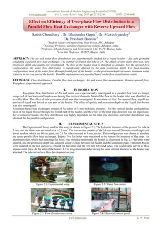
  • 1. International Journal of Modern Engineering Research (IJMER) www.ijmer.com Vol. 3, Issue. 4, Jul - Aug. 2013 pp-2275-2280 ISSN: 2249-6645 www.ijmer.com 2275 | Page Satish Choudhary1 , Dr. Bhupendra Gupta2 , Dr. Mukesh pandey3 Dr. Prashant Baredar4 1 Student, Master of Engineering, Heat Power, JEC, Jabalpur 2 Assistant Professor, Jabalpur Engineering College, Jabalpur, India 3 Professor, School of Energy and Environment, UIT, RGPV Bhopal, India 4 Associate Professor, MANIT, Bhopal, India ABSTRACT: The air and water flow distribution are experimentally studied for a round header – flat tube geometry simulating a parallel flow heat exchanger. The number of branch flat tube is 25. The effects of tube outlet direction, tube protrusion depth and quality are investigated. The flow at the header inlet is identified as annular. For the upward flow configuration, the water flow distribution is significantly affected by the tube protrusion depth. For flush-mounted configuration, most of the water flows through frontal part of the header. As the protrusion depth increases, minimum water is forced to the rear part of the header. Possible explanations are provided based on the flow visualization results. KEYWORDS: Flow distribution; Parallel flow heat exchanger; Air and water flow measurement; Reverse upward flow; Two-phase; Experimental approach. I. INTRODUCTION Two-phase flow distribution of Air and water was experimentally investigated in a parallel flow heat exchanger comprised of two horizontal headers and twenty five vertical channels. Most of the flow in the header inlet was identified as stratified flow. The effect of tube protrusion depth was also investigated. It was observed that, For upward flow, significant portion of liquid was forced to rear part of the header. The effect of quality and protrusion depth on the liquid distribution was also investigated. Aluminum based heat exchangers consist of flat tubes of 5 mm hydraulic diameter. For the vertical header configuration, most of the liquid flowed through the frontal part of the header, and the effect of the inlet pipe direction was not significant. For a horizontal header, the flow distribution was highly dependent on the inlet pipe direction, and better distribution was obtained for the parallel configuration. II. EXPERIMENTAL SETUP The Experimental Setup used for this study is shown in Figure 2.1. The hydraulic diameter of the present flat tube is 5 mm, and the flow cross sectional area is 25 mm2 . The test section consists of the 16 mm internal Diameter round upper and lower headers, which are 90 cm apart, and 25 flat tubes inserted at 3 mm pitches. This configuration was chosen to simulate the actual parallel flow heat exchanger. Twenty five flat holes were machined at the bottom for insertion of flat tubes. An aluminum plate, which had matching flat holes, was installed underneath the header as illustrated in Fig. 2.1Flat tubes were secured, and the protrusion depth was adjusted using O-rings between the header and the aluminum plate. Transition blocks were installed in the test section to connect the flat tubes and the 5.0 mm ID round tubes. The round tubes served as flow measurement lines. At the inlet of the header, 1.0 m long aluminum tube having the same internal diameter as the header was attached. The tube served as a flow development section. Figure 2.1: Experimental setup Figure 2.2: Water flow meter Figure 2.3: Flow distribution system Figure 2.4: Electrical control panel Effect on Efficiency of Two-phase Flow Distribution in a Parallel Flow Heat Exchanger with Reverse Upward Flow
  • 2. International Journal of Modern Engineering Research (IJMER) www.ijmer.com Vol. 3, Issue. 4, Jul - Aug. 2013 pp-2275-2280 ISSN: 2249-6645 www.ijmer.com 2276 | Page Table 2.1: Components used in Setup Sr.No. Name of component Specification 1 Air blower 15 amp.220 v ac 2 Water heater 1000 w 3 Water pump 65w 4 Water flow meter ½ inch Diameter 5 Air flow meter ½ inch Diameter 6 Air and water Separator 4 inch Diameter 7 Flexible pipe 15 mm Diameter 8 Thirteen valve ½ inch Diameter 9 Vertical square aluminum pipe Thickness 1.5mm 10 Vertical circular aluminum pipe Thickness 1.5mm 11 Inlet tank 40Liters 12 Outlet tank 25 Liters 13 Electrical control panel 15 amp. III. METHODOLOGY III.1. UPWARD FLOW: An upward flow was observed at the header inlet. The liquid motion in the lower header was unstable and intermittent. Liquid was supplied into the channels by electrical water pump. The Air and water distribution is generally reverse to the liquid distribution. The flow visualization results that the liquid is forced to frontal part of the header as the quality increases. The liquid is forced to frontal part of the header as the quality decreases, yielding better liquid distribution. The explanation at lower quality, more liquid is supplied into the header, supplying more liquid to frontal part may be provided. The annular flow using air and water revealed that more water was forced to frontal part of the header at a higher quality. The reason was attributed to the increased water film thickness at the upper part of the header at increased quality. The part of the incoming water impinges at the first protrusion, separates at the top, reattaches at the bottom of the header due to the action of gravity. The separated water, along with the water from lower part of the header, is forced to the rear end of the header, and starts to fill in the tubes from backward. IV. RESULT AND DISCUSSION IV.1. Reverse upward flow: In reverse upward flow, the air and water are flow in the direction of upward and after that air and water are achieve in separator. Temperature at inlet is 50 °C., Temperature at outlet is 45.8 °C. Time taken during reading = 10 sec. Temperature at inlet =50 °C Temperature at outlet =45.8 °C H= witch insert in pipe D= 16mm diameter of pipe Table 4.1.1: Air flow in different h/d and Reverse upward flow Sr. No. Channel no. Air flow (m3 /sec) At h/d = 0/16 =0.0 Air flow (m3 /sec) At h/d = 4/16 =0.25 Air flow (m3 /sec) At h/d =8/16 =0.5 1 1-5 0.5 1.5 1.5 2 6-10 1.2 1.4 1.2 3 11-15 1.3 1.2 1.0 4 16-20 0.5 0.5 1.0 5 21-25 0.2 0 0.0 Fig. 4.1.1: Air flow in different h/d and Reverse upward flow
  • 3. International Journal of Modern Engineering Research (IJMER) www.ijmer.com Vol. 3, Issue. 4, Jul - Aug. 2013 pp-2275-2280 ISSN: 2249-6645 www.ijmer.com 2277 | Page Table 4.1.2 Water flow in different h/d and Reverse upward flow Sr. No. Channel no. Water flow (L/ sec) At h/d = 0/16 =0.0 Water flow (L/ sec) At h/d = 4/16 =0.25 Water flow (L/ sec) At h/d = 8/16 =0.5 1 1-5 2.0 0.5 0.4 2 6-10 0.5 0.4 0.5 3 11-15 0.4 0.4 0.5 4 16-20 1.0 0.5 1.4 5 21-25 2.2 1.5 2.3 Figure 4.1.2: Water flow in different h/d and Reverse upward flow Efficiency: Temperature at inlet =50 °C Temperature at outlet =45.8 °C ή= (Temperature at inlet - Temperature at outlet) / Temperature at inlet = (50-45.8)/50 =08.40% IV.2. REVERSE UPWARD FLOW: In reverse upward flow, the air and water are flow in the direction of upward and after that air and water are achieve in separator. Temperature at inlet is 60 °C., Temperature at outlet is 53.6 °C. Time taken during reading = 10 sec. Temperature at inlet =60 °C. Temperature at outlet =53.6 °C H= witch insert in pipe D= 16 mm diameter of pipe Table 4.2.1: Air flow in different h/d and Reverse upward flow Sr. No. Channel no. Air flow (m3 /sec) At h/d = 0/16 =0.0 Air flow (m3 /sec) At h/d = 4/16 =0.25 Air flow (m3 /sec) At h/d =8/16 =0.5 1 1-5 0.6 1.6 1.5 2 6-10 1.3 1.5 1.3 3 11-15 1.4 1.3 1.2 4 16-20 0.7 0.4 1.1 5 21-25 0.2 0.3 0.1 Figure 4.2.1: Air flow in different h/d and Reverse upward flow
  • 4. International Journal of Modern Engineering Research (IJMER) www.ijmer.com Vol. 3, Issue. 4, Jul - Aug. 2013 pp-2275-2280 ISSN: 2249-6645 www.ijmer.com 2278 | Page Table 4.2.2: Water flow in different h/d and Reverse upward flow Sr. No. Channel no. Water flow (L/ sec) At h/d = 0/16 =0.0 Water flow (L/ sec) At h/d = 4/16 =0.25 Water flow (L/ sec) At h/d = 8/16 =0.5 1 1-5 2.1 0.5 0.4 2 6-10 0.6 0.4 0.5 3 11-15 0.5 0.4 0.6 4 16-20 1.2 0.5 0.9 5 21-25 2.4 0.9 1.6 Figure 4.2.2: Water flow in different h/d and Reverse upward flow Efficiency Temperature at inlet =60 °C. Temperature at outlet =53.6 °C ή= (Temperature at inlet - Temperature at outlet) / Temperature at inlet = (60-53.6)/60 =10.66% IV.3. REVERSE UPWARD FLOW: In reverse upward flow, the air and water are flow in the direction of upward and after that air and water are achieve in separator. Temperature at inlet is 70 °C., Temperature at outlet is 63.8 °C. Time taken during reading = 10 sec. Temperature at inlet =70 °C Temperature at outlet =63.8 °C H= witch insert in pipe D= 16mm diameter of pipe Table 4.3.1: Air flow in different h/d and Reverse upward flow Sr. No. Channel no. Air flow (m3 /sec) At h/d = 0/16 =0.0 Air flow (m3 /sec) At h/d = 4/16 =0.25 Air flow (m3 /sec) At h/d =8/16 =0.5 1 1-5 0.7 1.7 1.6 2 6-10 1.4 1.6 1.3 3 11-15 1.6 1.4 1.2 4 16-20 0.8 0.5 1.2 5 21-25 0.1 0.9 0.2 Figure 4.3.1: Air flow in different h/d and Reverse upward flow
  • 5. International Journal of Modern Engineering Research (IJMER) www.ijmer.com Vol. 3, Issue. 4, Jul - Aug. 2013 pp-2275-2280 ISSN: 2249-6645 www.ijmer.com 2279 | Page Table 4.3.2: Water flow in different h/d and Reverse upward flow Sr. No. Channel no. Water flow (L/ sec) At h/d = 0/16 =0.0 Water flow (L/ sec) At h/d = 4/16 =0.25 Water flow (L/ sec) At h/d = 8/16 =0.5 1 1-5 2.3 0.5 0.5 2 6-10 0.7 0.4 0.6 3 11-15 0.6 0.4 0.7 4 16-20 1.3 0.5 2.2 5 21-25 2.4 0.9 2.4 Figure 4.3.2: Water flow in different h/d and Reverse upward flow Efficiency Temperature at inlet =70 °C Temperature at outlet =63.8 °C ή= (Temperature at inlet - Temperature at outlet) / Temperature at inlet = (70-63.8)/70 =8.85% IV.4. REVERSE UPWARD FLOW: In reverse upward flow, the air and water are flow in the direction of upward and after that air and water are achieve in separator. Temperature at inlet is 80 °C and temperature at outlet is 73.2 °C. Time taken during reading = 10 sec. Temperature at inlet =80°C Temperature at outlet =73.2 °C H= witch insert in pipe D= 16mm diameter of pipe Table 4.4.1: Air flow in different h/d and Reverse upward flow Sr. No. Channel no. Air flow (m3 /sec) At h/d = 0/16 =0.0 Air flow (m3 /sec) At h/d = 4/16 =0.25 Air flow (m3 /sec) At h/d =8/16 =0.5 1 1-5 0.8 1.8 1.7 2 6-10 1.4 1.6 1.4 3 11-15 1.6 1.5 1.3 4 16-20 0.9 0.6 1.4 5 21-25 0.2 0.4 0.4 Figure 4.4.1: Air flow in different h/d and Reverse upward flow
  • 6. International Journal of Modern Engineering Research (IJMER) www.ijmer.com Vol. 3, Issue. 4, Jul - Aug. 2013 pp-2275-2280 ISSN: 2249-6645 www.ijmer.com 2280 | Page Table 4.4.2: Water flow in different h/d and Reverse upward flow Sr. No. Channel no. Water flow (L/ sec) At h/d = 0/16 =0.0 Water flow (L/ sec) At h/d = 4/16 =0.25 Water flow (L/ sec) At h/d = 8/16 =0.5 1 1-5 2.4 0.6 0.5 2 6-10 0.8 0.5 0.6 3 11-15 0.7 0.5 0.8 4 16-20 1.4 0.6 1.6 5 21-25 2.3 1.2 2.5 Figure 4.4.2: Water flow in different h/d and Reverse upward flow Efficiency: Temperature at inlet =80°C Temperature at outlet =73.2 °C ή= (Temperature at inlet - Temperature at outlet) / Temperature at inlet = (80-73.2)/80 = 08.50% V. CONCLUSION [1] The effects of tube outlet direction, tube protrusion depth and quality are investigated. It is observed that the incoming water impinges at the protrusions, and the separated water reattaches at the rear part of the header. The reattachment length increases as the protrusion depth increases. The effect of quality is qualitatively the same as that of the protrusion depth. Increase of the mass flux or quality forces the water to rear part of the header. [2] For the upward flow configuration, most of the water flows through the rear part of the header. The protrusion depth, quality does not significantly alter the flow distribution. Different from the downward flow configuration, the separated water from upper protrusions reattaches at the bottom of the header. [3] Thus, the variation of reattachment length by the change of protrusion depth, quality is not like to significantly affect the flow distribution. Negligible difference on the water flow distribution was observed between the parallel flow and the reverse flow configuration. Using of Reverse upward flow the obtain maximum efficiency are 10.66% at Temperature at inlet =60 °C and Temperature at outlet =53.6 °C REFERENCES [1]. C. Schenone et.al. (2008) Experiments on two-phase flow distribution inside parallel channels of compact heat exchangers International Journal of Multiphase Flow 34 (2008) 128–144. [2]. Galip Temir et. al. (2009) Heat transfer of horizontal parallel pipe ground heat exchanger and experimental verification Applied Thermal Engineering 29 (2009) 224–233. [3]. Karen A. Thole et.al. (1999) Entry region of louvered ®n heat exchangers Experimental Thermal and Fluid Science 19 (1999) 223=232. [4]. Lee, J.K., et.al.., (2004). Distribution of two-phase annular flow at header-channel junctions. Exp. Therm. Fluid Sci. 28, 217– 222. [5]. Rong, X., et.al. (1995). Two-phase header flow distribution in a stacked plate heat exchanger. Gas Liquid Flows Fed- Vol. 225, 115–215. [6]. Tompkins, et.al. (2002). Flow distribution and pressure drop in micro channel manifolds. In: 9th Int. Refrigeration and Air Conditioning Conference at Purdue, R6-4. [7]. Tae-Ryong Sin et. al. (2006) Two-phase flow distribution of air–water annular flow in a parallel flow heat exchanger International Journal of Multiphase Flow 32 (2006) 1340–1353. [8]. Visit, S., et.al (2004). Two-phase flow distribution in compact heat exchanger manifolds. Exp. Thermal Fluid Sci. 28, 209–215. [9]. Watanabe, et.al (1995). Two-phase flow distribution in multi-pass tube modeling serpentine type evaporator. ASME/JSME Thermal Eng. Conf. 2, 35–42. [10]. Yansong Ma et. al. (2010) Experimental investigation of header configuration on two-phase flow distribution in plate-fin heat exchanger International Communications in Heat and Mass Transfer 37 (2010) 116–120.