Removal of Clutter by Using Wavelet Transform For Wind Profiler

ABSTRACT: Removal of clutter in the radar wind profiler is the utmost important consideration in radar. Wavelet transform is very effective method to remove the clutter. This paper presents a technique based on the wavelet transform to remove the clutter. In this technique we used Fourier transform and descrete wavelet transform after that applied inverse discrete wavelet transform for signal. These techniques applied for inphase and quadrature phase, total spectrum and single range gate. Very encouraging results got with this technique that have shown practical possibilities for a real time implementation and for applications related to frequency domain. Keywords: Wind profiler, wavelet transform, Fourier transform, clutter, signal processing

Recommandé
Contenu connexe
Tendances
Tendances (20)
En vedette
En vedette (20)
Similaire à Removal of Clutter by Using Wavelet Transform For Wind Profiler
Similaire à Removal of Clutter by Using Wavelet Transform For Wind Profiler (20)
Plus de IJMER
Plus de IJMER (20)
Removal of Clutter by Using Wavelet Transform For Wind Profiler
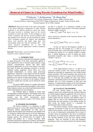
- 1. International Journal of Modern Engineering Research (IJMER) www.ijmer.com Vol.2, Issue.6, Nov-Dec. 2012 pp-4591-4594 ISSN: 2249-6645 Removal of Clutter by Using Wavelet Transform For Wind Profiler P.Srilaxmi, 1 I. Kullayamma, 2 M. Durga Rao3 1 Department of ECE, SVU College of Engineering, Tirupati, Andhra Pradesh, India 2 Assistant Professor, Department of ECE, SVU College of Engineering, Tirupati, Andhra Pradesh, India. 3 Scientist Engineer SC-D, NARL, Gadanki ABSTRACT: Removal of clutter in the radar wind profiler (u) that is a function of a continuous variable in one is the utmost important consideration in radar. Wavelet dimension called the signal domain.† Its Fourier transform, transform is very effective method to remove the clutter. denoted as X(Ω), is given by This paper presents a technique based on the wavelet X (Ω) = ) du Ω ∈ (−∞,∞) (1) transform to remove the clutter. In this technique we used Fourier transform and descrete wavelet transform after And is said to be a function in the transform domain. The that applied inverse discrete wavelet transform for signal. inverse transform is These techniques applied for inphase and quadrature phase, total spectrum and single range gate. Very encouraging results got with this technique that have X (u) = ) du u ∈ (−∞, ∞) (2) shown practical possibilities for a real time implementation and for applications related to frequency In Esq. (1) And (2), the frequency variable is in domain. radians per unit of u. For example, if u = t, that is, u is in units of seconds, then is the usual radian frequency in units Keywords: Wind profiler, wavelet transform, Fourier of radians per second; if u is a spatial variable in meters, transform, clutter, signal processing. then is spatial frequency in units of radians per meter. Equivalents transform pair using a cyclical frequency I. INTRODUCTION variable F =Ω /2π is Wavelet analysis attracted much attention recently in signal processing. It has been successfully applied in X (F) = ) du F ∈ (−∞,∞) many applications such as transient signal analysis, image analysis, communication systems and other signal X (u) = ) dF u ∈ (−∞,∞) processing applications. It is not a new theory in the sense that many of ideas and techniques involved in wavelets If the signal domain is time (u = t), then F is in (subband coding, quadrature mirror filters etc.) were cycles per second, or hertz. The various wavelet analysis devolped independently in various signal processing methods are described in comparison to the widely known applications. Especially, it has turned out that the specific Fourier transform. The Fourier transform only retrieves the features of wavelets can also be efficiently used for certain global frequency content of a signal, all time information is problems in the context of radar signal analysis. The aim of lost. To overcome this problem the short time Fourier this paper is to give an overview on the analysis of RWP transform is developed, however this method suffers from a data and to explain how wavelets can be utilized for clutter limitation due to a fixed resolution in both time and removal. frequency. A multiresolution analysis of the local frequency The goal of RWP systems is to gather information content of a signal is made possible by wavelet analysis. concerning the three dimensional atmospheric wind vectors. Radio frequency pulses are emitted and backscattered from III. WAVELET TRANSFORMS small in homogeneities in the atmosphere. The term wavelet means a small wave. The The reflected signal is sampled at certain rates smallness refers to the condition that this (window) function corresponding to different heights. The Doppler shift of the is of finite length (compactly supported). The wave refers to atmospheric (clear-air) signal, which can assumed to be the condition that this function is oscillatory. The term constant over the small measurement period mother implies that the functions with different region of (quasistationarity), generates a peak in the Fourier power support that are used in the transformation process are spectrum. derived from one main function, or the mother wavelet. In other words, the mother wavelet is a prototype for II. FOURIER TRANSFORMS generating the other window functions. The Fourier transform is as ubiquitous in radar Like Fourier analysis, wavelet analysis deals with signal processing as in most other signal processing fields. expansion of functions in terms of a set of basis functions. Frequency domain representations are often used to Unlike Fourier analysis, wavelet analysis expands functions separate desired signals from interference; the Doppler shift not in term of trigonometric polynomials but in terms of is a frequency domain phenomenon of critical importance; wavelets which are generated in the form of translations and it will be seen that in some radar systems, especially and dilations of a fixed function called the mother wavelet. imaging systems, the collected data are related to the The wavelets obtained in this way have special scaling desired end product by a Fourier transform. Both properties. They are localized in time and frequency, continuous and discrete signals are of interest, and therefore permitting a closer con nection between the function being Fourier transforms are required for both. Consider a signal x www.ijmer.com 4591 | Page
- 2. International Journal of Modern Engineering Research (IJMER) www.ijmer.com Vol.2, Issue.6, Nov-Dec. 2012 pp-4591-4594 ISSN: 2249-6645 represented and their coefficients. Greater numerical except under unusual conditions. The development of stability in reconstruction and manipulation is ensured. modern wind profiler is an outgrowth of research work The objective of wavelet analysis is to define these done with radars designed to probe the ionosphere, where powerful wavelet basis functions and find efficient methods longer wavelengths and extreme sensitivity was required. for their computation. It can be shown that every application using the fast Fourier transform (FFT) can be BASIC PRINCIPLE OF WIND PROFILING RADARS formulated using wave lets to provide more localized Wind profiling radars depend upon the scattering temporal (or spatial) and fre quency information. Thus, of electromagnetic energy by minor irregularities in the instead of a frequency spectrum, for example, one gets a index of refraction of the air. The index of refraction is a wavelet spectrum. In signal process ing, wavelets are very measure of the speed at which electromagnetic waves useful for processing nonstationary signals. A major propagate through a medium. For wind profiling, this advance in wavelet theory was the discovery of smooth medium is the atmosphere. A spatial variation in this index mother wavelets whose set of discrete translations Two encountered by a propagating electromagnetic (radio wave) different kinds of wavelet transform can be distinguished, a causes a minute amount of the energy to be scattered (or continuous and a discrete wavelet transform. The dispersed) in all directions. Most of the energy incident on continuous wavelet transform is calculated by the the refractive irregularity propagates through it without convolution of the signal and a wavelet function. A wavelet being scattered. function is a small oscillatory wave which contains both The analysis and the window function. The V. SIGNAL PROCESSING discrete wavelet transform uses filter banks for the analysis The purpose of radar signal processing is to extract and synthesis of a signal. The filter banks contain wavelet desired data from radar backscattered echoes. The desired filters and extract the frequency content of the signal in data usually concerns the detection of a target of interest, various sub bands. the location of the target in space. The accuracy of the data available from radar is CONTINUOUS WAVELET TRANSFORM limited by thermal noise introduced by the radar receiver, At the most redundant end, one has the CWT. For echoes from targets of no interest (clutter), and externally CWT the parameters vary in a continuos fashion. This generated interface. representation offers the maximum freedom in the choice of Radar signal processing is used to enhance signals the analysis wavelet. The only requirement is that the and to suppress clutter and externally generated signals. In wavelet satisfies an admissibility condition; in particular it the case of atmospheric radars the target generated by the must have zero mean. The condition is also crucial to be process of refractive index fluctuations. These signals are CWT invertible on its range. very weak even for powerful radar systems. So, sophisticated signal processing technique is required to DISCRETE WAVELET TRANSFORM extract these signals. Here, we have discrete function f(n) and the definition of An elementary form of radar consists of discrete wavelet transform (DWT) is given by transmitter, antenna and an energy detecting device, which C(a,b) =C( j,k ) ѱj,k(n) may be receiver. Single antenna is used for both Where ѱj,k is a discrete wavelet defined as: transmission and reception. The signal transmitted by the ѱj,k(n)=2-j/2ѱ(2-jn –k) transmitting antenna gets reflected by the target and is re- The parameters a,b are defined in such a way that a = 2j,b = radiated in all directions. This energy re-radiated in the 2j k . Sometimes the analysis is called dyadic as well. One backward directions, is of prime interest to radar. of the function of wavelet transform is Daubechies. DAUBECHIES The Daubechies familie is named after Ingrid Daubechies who invented the compactly supported orthonormal wavelet, making wavelet analysis in discrete time possible. The first order Daubechieswavelet is also known as the Haar wavelet, which wavelet function resembles a step function. Higher order Daubechies functions are not easy to describe with an analytical expression. Theorder of the Daubechies functions denotes the number of vanishing moments, or the number of zero moments of the wavelet function. This is weakly related to the number of oscillations of the wavelet function. The larger the number of vanishing moments, the better the frequency localization of the decomposition. IV. WIND PROFILING RADARS Conventional Doppler weather radars, which are designed to detect hydrometeor, are not sensitive enough because of their short wavelengths to detect the clear air, www.ijmer.com 4592 | Page
- 3. International Journal of Modern Engineering Research (IJMER) www.ijmer.com Vol.2, Issue.6, Nov-Dec. 2012 pp-4591-4594 ISSN: 2249-6645 Fig (a): Processing steps for extraction of parameters Figure2.shows the Quadrature phase signal in which we have both signals. which are before and after The receiving antenna captures the returned wavelets. signals and channels it to the receiver, where it is processed By using wavelet transform remove the clutter in to detect the presence of target and to extract its location inphase and quadrature signals. and relative velocity. The distance of the target is determined by measuring the time taken for the radar signal to travel between target and radar the shift in carrier of the reflected wave is a measure of the target’s relative velocity and may be used to distinguish moving objects from stationary objects. to the target and back. If relative motion exists NARL LAWP Most important feature or NARL LAWP is the simplified active array configuration. In this configuration, each element of the planar micro strip patch antenna array is fed directly by dedicated low power solid-state Figure 1. Time-series data from a 1280MHz wind transceiver module consisting of a power amplifier (PA) profiler.The original inphasecomponent is shown in blue, and LNA connected to the common antenna port through a the wavelet re moved clutter component in red. circulator. A transmit/receive (T/R) switch switches the input port between the PA and LNA. These transceiver modules are made with commercially available communication components, making them low cost and affordable. Signal-to-Noise Ratio (SNR), thereby the range performance is significantly improved as the feed loss is eliminated. This configuration reduces the antenna size significantly (at least by a factor of 4-6) when compared to a conventional passive array system for the given range performance and makes the wind profiler compact and transportable. The second important feature of this system is the utilization of a low power two-dimensional passive multi-beam forming network, which simplifies the beam Figure 2. Time-series data from a 1280MHz wind formation. profiler.The original quadrature component is shown in IN-PHASE AND QUADRATURE COMPONENTS blue, the wavelet re moved clutter component in red. Method and apparatus are disclosed for correcting amplitude and phase imbalances between the "in phase" and Figure3. Shows the power spectrum compared to the after "quadrature" channels of a digital signal processor by wavelet. This spectrum for single range gate. The descrete waveet transform is used for to remove the clutter which is determining a correction coefficient from a test signal present in the range gate periodically introduced into the quadrature phase detector . of a radar system. Figure4. Shows the power spectrum before the wavelet The frequency spectrum of the signal at the output of the phase detector in response to each such test signal is transform. In which clutter is present. utilized to produce a correction coefficient for application to radar return signals passing through the phase detector Figure5. Shows the power spectrum after the wavelet. during normal radar operation, thereby providing true In which clutter is removed.We collect the LAWP data upto 7km. quadrature radar return signals for digital processing. The ground clutter signal characteristic with a 90- degree phase difference between I and Q components. The mountains through the radar beam causes a frequency sweep, and a localized appearance during the dwell period. This type of vibrating signal can be analyzed with the discrete wavelets. The frequency presentation of a discrete wavelet that covers a band of frequencies. In the time-domain, the wavelet consists of real and imaginary sinusoidal wavelets that closely match with the mountain signal.The discrete wavelet transform can be calculated using a Fast Fourier Transform. To avoid frequency leakage, a strong radar return signal should first be removed with the wavelet method. Figure 3. power spectrum (blue) is compared to the Figure1.shows the inphase signal in which we removed clutter power spectrum (red). have both signals.which are before and after wavelets. www.ijmer.com 4593 | Page
- 4. International Journal of Modern Engineering Research (IJMER) www.ijmer.com Vol.2, Issue.6, Nov-Dec. 2012 pp-4591-4594 ISSN: 2249-6645 VII. ACKNOWLEDGEMENTS The Authors thank to M.Durga Rao, Scientist engineer,SC- D, National Atmospheric Research Laboratory Department of Space, Government of India Gadanki India and I .kullayamma,Assistant Professor, S.V.U. College Of Engineering,Tirupathi,India for their encouragement and infrastructure facilities to carry out this work. REFERENCES [1] Newland, D. E., 1994: Wavelet analysis of vibration, Part 1: Theory. J. Vibration Acoust, 116, 409–416. [2] Anandan, V. K., Atmospheric Data Processor – Technical and User reference manual, National Atmospheric Research Laboratory, Gdansk. [3] Liu, P. C., and G. S. Miller, 1996: Wavelet transforms and ocean current data analysis. J. Atmos. Oceanic Technol., 13, Figure4. Power spectra before wavelets. 1090–1099. [4] BOISSE, J.-C., V. KLAUS, J.-P. AUBAGNAC, 1999: Wavelets transform technique for removing airplane echos from ST radar signals. – J. Atmos. Oceanic Technol. 16,334–346. [5] HLAWATSCH, F., G. BOUDREAUX- BARTELS, 1992: Linear and quadratic Time- frequency signal representations. –IEEE Sig. Proc. Magazine, 21–67. [6] FLANDRIN, P., 1999: Time-Frequency / Time- Scale Analysis. Wavelet Analysis and Its Applications. – Academi Press. [7] DAUBECHIES, I., 1992: Ten Lectures on Wavelets. – SIAM, Philadelphia. [8] COHEN, L., 1989: Time-frequency distributions –A review. –Proc. IEEE 77(7), 941–981. [9] Riddle, A.C., and W.M. Angevine, 1992: Ground Clutter removal from profiler spectra. Proc. Fifth Workshop of Technical and Scientific Aspects of MST Radar, Figure5. Power spectra after wavelets. Aberystwyth, Wales, United Kingdom, URSI/SCOSTEP 418- 420. VI. CONCLUSION [10] Benjamin, Z. B., and D. S. Zrnic, 1991: Clutter Rejection for Doppler weather radars which use Staggered pulses. The wavelet transform method presented in this IEEE Trans. Geosci. Remote Sens., 29, 610–620. paper can efficiently remove clutter appearing in wind [11] F. C. A. Fernandes, R. v. Spaendonck, M. J. Coates, and S. profiler. Signals represented in the time domain can be Burrus, Directional Complex-Wavelet Processing," evaluated for their properties in the frequency Domain by Proceedings of Society of Photo-Optical applying signal analysis. InstrumentalEngineers|SPIE2000, Wavelet Applications in The most commonly known method to analyze a Signal Processing VIII, San Diego. , 2000. time signal for its frequency content is the Fourier [12] Strang, G., and T. Nguyen, 1996: Wavelets and Filter transform. The wavelet transform is a relatively new Banks. Wellesley- Cambridge Press, 490pp. technique which has some attractive characteristics. It has been found by the discrete wavelet transform. The raw data is stored in host processor first it converts into spectral data. Spectral data is also stored in digital receiver. The spectral data is processed by MATLAB programming. The clutter is removed from the inphase and quadrature phase signals and also from the total spectrum by using the discrete wavelet transform for LAWP radar which is used at NARL, Gadanki. By using different wavelet transform techniques the clutter is removed from the wind profiler. www.ijmer.com 4594 | Page