White Line Follower Using Fire Bird V Robot

Robotic technology has the origin from the year 1954 and has very vast application in the field like energy, health, agriculture, education, research, motion and space etc. The disadvantage of any autonomous robot is that, it is very difficult to maintain stability of its traverse condition. In this paper, we have introduced and achieved maximum stability for the traverse condition through white line following technique. Here we are using the Fire Bird V robotic technology as our robotic medium, which has the Atmega2560 as its microcontroller and where it uses Studio 4 as its controller’s software platform. The control dynamic to the robot is sent via the software platform which is embedded ‘C’ language and the traverse condition is maintained. This robot runs at step down voltage value of 9V AC supply and has also uses lithium 9v battery as a stand by back up.

Recommandé
Contenu connexe
Tendances
Tendances (20)
En vedette
Similaire à White Line Follower Using Fire Bird V Robot
Similaire à White Line Follower Using Fire Bird V Robot (20)
Plus de IJSRD
Plus de IJSRD (20)
Dernier
Dernier (20)
White Line Follower Using Fire Bird V Robot
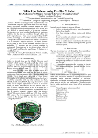
- 1. IJSRD - International Journal for Scientific Research & Development| Vol. 3, Issue 10, 2015 | ISSN (online): 2321-0613 All rights reserved by www.ijsrd.com 224 White Line Follower using Fire Bird V Robot RM.Nachammai1 N.Mrujool Kansara2 G.Lavanya3 R.Gopalakrishnan4 1,2,3 Student 4 Assistant Professor 1,2,3,4 Department of Instrumentation and Control Engineering 1,2,3,4 Saranathan College of Engineering, Panjapur, Tiruchirapalli Tamilnadu Abstract— Robotic technology has the origin from the year 1954 and has very vast application in the field like energy, health, agriculture, education, research, motion and space etc. The disadvantage of any autonomous robot is that, it is very difficult to maintain stability of its traverse condition. In this paper, we have introduced and achieved maximum stability for the traverse condition through white line following technique. Here we are using the Fire Bird V robotic technology as our robotic medium, which has the Atmega2560 as its microcontroller and where it uses Studio 4 as its controller‟s software platform. The control dynamic to the robot is sent via the software platform which is embedded „C‟ language and the traverse condition is maintained. This robot runs at step down voltage value of 9V AC supply and has also uses lithium 9v battery as a stand by back up. Key words: IR Sensor, Proximity Sensor, Position Encoder, White Line Sensor, Photo Transistor, Buzzer, LED I. INTRODUCTION Robot is derived from an Old Church Slavonic word “robota” which means “forced labor”. So robots were designed to help the human in order to reduce our work pressure. The first programmable robot was designed by George Devol in the year 1954. Here we use a Fire Bird V robot which is a microcontroller based robot used for any kind of robotic application. This was designed by IIT-Bombay along with MHRD. This is based upon a principal of „Open Source Philosophy‟ in its software and hardware design therefore it would be compatible with any other software like Keil, Matlab, Scilab and LabVIEW. By using this robot we could make use of complex applications to run on it. It has the name Fire Bird V robot because it is the 5th in it series. It uses 2 atmega controller where it acts as a master and a slave controller. The basic components in this robot is that it has IR sensors, proximity sensors, white line sensors, SHARP IR sensors, buzzers, LCD and LED along with Ni- MH battery. The two Atmega controllers are the master control is the Atmega 2560 and the slave control is the Atmega 8 controller. Fig. 1: The Basic Structure of Fire Bird V Robot II. NEED FOR ROBOTICS In simple words this can be given as follows: Robots are employed in places where human can‟t be involved directly. E.g. Deep mining, welding, cutting and drilling areas. It can be used in jobs where it is stressful, boring or labour intensive for humans. It can be used in places where human doesn‟t want to do the kind of job like cleaning of under -ground drainage system. III. ROBOTIC LAWS The law of robotics was well defined by the scientist Issac Asimov. The robotic laws are stated as follows: A robot may not injure a human being or through inaction allow a human being to come to any harm. A robot must obey the orders given to it by human beings except where such orders would not conflict the first law. A robot must protect its own existence as long as such protection does not conflict with the first or second law. IV. APPLICATION Robots include all branches of engineering since each part of the robot has various branches of engineering involved in designing. These branches constitute of electrical, electronics, mechanical, computer science, instrumentation along with the physics and mathematics. Therefore robots have a wider application range. Some of the application areas are General purpose autonomous robots Industrial robots Educational robots Military robots Healthcare robots Research robots Entertainment
- 2. White Line Follower using Fire Bird V Robot (IJSRD/Vol. 3/Issue 10/2015/053) All rights reserved by www.ijsrd.com 225 V. BLOCK DIAGRAM Fig. 2: Basic Block Diagram of Atmega 2560 based Robot VI. DESIGN OF THE SYSTEM The basic block diagram of Atmega 2560 based robot is shown above. The various components involved in designing of the white line follower robot consist of the following Power management Sensing Actuation(locomotion) Communication Intelligence(microcontroller) Other peripherals A. Power Management: Fire Bird v robot uses a nickel metal hydride (Ni-MH) battery with a 9.6V rechargeable pack. The battery voltage can vary between 12V (fully charged) and 8V (discharged) condition. B. Sensors: Sensor is an object which is used to sense an event or changes in the area. Sensors are basically a transducer and they give the output in electrical or optical terms. In this robot the following sensors are being used. The sensors include Sharp IR sensors Analog IR Proximity sensors White line sensors Position encoder Infrared TSOP sensor(photo transistor) Servo mounted sensor pod Accelerometer Gyroscope Ultrasonic sensor Motion sensor C. Actuators: Actuator is a type of motor that is responsible for controlling a mechanism. Here the actuators are used for moving the robot. The following are being used in it. This includes Two 60rpm geared motor Servo motor D. Communication: Communication between the robot and the system can be done through two modes. Here the robot could talk or communicate with other robot or PC. They are Wired communication Wireless communication In wired communication the data transfer takes place with the help of cables. The commonly used cables are USB, RS-232 cables and USB to serial communication cables etc. In wireless communication the data transfer takes place with the help of other devices which acts as an intermediate device through protocols. These devices include Zigbee based on IEEE 802.15.4protocols, Wi-Fi communication, Bluetooth communication and infrared remote mode. E. Intelligence: The language used for programming is „embedded C‟ which is similar to C program. Here the microcontroller or microprocessor acts as the brain of the robot. Here the ATMEL manufactured AVR architecture based Atmega 2560 controller acts as the master controller while the Atmega 8 controller acts as the slave controller. F. Other Peripherals: The other peripherals consist of the indicating or displaying devices. These displays are used to indicate the final value or indicate if any error is present by displaying or by giving sound. The devices used for indicating are 16 x 2 alpha numeric LCD LED Buzzer VII. WORKING OF THE SYSTEM Here as the name indicates white line sensor are being used for tracking the white line on the surface. They are used for sensing the location of the system there by tracking could be done. The sensing of the line is done by a red LED which is used to illuminate the path of white line and a phototransistor is used for sensing the line. This LED and photo transistor forms the major part of white line sensor. Here the path of the robot is found whether it is going in the right path or not is found out by using a simple mechanism. When the robot tracks the white line more amount of light gets illuminated in the path and therefore the leakage current is also high. If the path is not tracked properly the leakage current value is decreased since the amount of light illuminated is also less. Fig. 3: A Schematic Diagram of White Line Sensor Module in Main Board
- 3. White Line Follower using Fire Bird V Robot (IJSRD/Vol. 3/Issue 10/2015/053) All rights reserved by www.ijsrd.com 226 VIII. ADVANTAGE OF USING RED LED The main advantage of using red LED is that It is near to the infra red region It could be easily seen with eyes and used for easier calibration All phototransistor and photo diodes are sensitive to infra red but not to red light IX. CODING The coding used for designing the tracking of the surface is done through embedded c program. The following coding is being used for sensing the white line #include <avr/io.h> #include <avr/interrupt.h> #include <util/delay.h> #include <math.h> #include "lcd.c" void port_init(); void timer5_init(); void velocity(unsigned char, unsigned char); void motors_delay(); unsigned char ADC_Conversion(unsigned char); unsigned char ADC_Value; unsigned char flag = 0; unsigned char Left_white_line = 0; unsigned char Center_white_line = 0; unsigned char Right_white_line = 0; void lcd_port_config (void) { DDRC = DDRC | 0xF7; PORTC = PORTC & 0x80; } void adc_pin_config (void) { DDRF = 0x00; PORTF = 0x00; DDRK = 0x00; PORTK = 0x00; } void motion_pin_config (void) { DDRA = DDRA | 0x0F; PORTA = PORTA & 0xF0; DDRL = DDRL | 0x18; PORTL = PORTL | 0x18; } void port_init() { lcd_port_config(); adc_pin_config(); motion_pin_config(); } void timer5_init() { TCCR5B = 0x00; TCNT5H = 0xFF; TCNT5L = 0x01; OCR5AH = 0x00; OCR5AL = 0xFF; OCR5BH = 0x00; OCR5BL = 0xFF; OCR5CH = 0x00; OCR5CL = 0xFF; TCCR5A = 0xA9; TCCR5B = 0x0B; } void adc_init() { ADCSRA = 0x00; ADCSRB = 0x00; ADMUX = 0x20; ACSR = 0x80; ADCSRA = 0x86; } unsigned char ADC_Conversion(unsigned char Ch) { unsigned char a; if(Ch>7) { ADCSRB = 0x08; } Ch = Ch & 0x07; ADMUX= 0x20| Ch; ADCSRA = ADCSRA | 0x40; while((ADCSRA&0x10)==0); a=ADCH; ADCSRA = ADCSRA|0x10; ADCSRB = 0x00; return a; } void print_sensor(char row, char coloumn,unsigned char channel) { ADC_Value = ADC_Conversion(channel); lcd_print(row, coloumn, ADC_Value, 3); } void velocity (unsigned char left_motor, unsigned char right_motor) { OCR5AL = (unsigned char)left_motor; OCR5BL = (unsigned char)right_motor; } void motion_set (unsigned char Direction) { unsigned char PortARestore = 0; Direction &= 0x0F; PortARestore = PORTA; PortARestore &= 0xF0; PortARestore |= Direction; PORTA = PortARestore; } void forward (void) { motion_set (0x06); } void stop (void) { motion_set (0x00); } void init_devices (void) { cli(); port_init();
- 4. White Line Follower using Fire Bird V Robot (IJSRD/Vol. 3/Issue 10/2015/053) All rights reserved by www.ijsrd.com 227 adc_init(); timer5_init(); sei(); } int main() { init_devices(); lcd_set_4bit(); lcd_init(); while(1) { Left_white_line = ADC_Conversion(3); Center_white_line = ADC_Conversion(2); Right_white_line = ADC_Conversion(1); flag=0; print_sensor(1,1,3); print_sensor(1,5,2); print_sensor(1,9,1); if(Center_white_line<0x28) { flag=1; forward(); velocity(150,150); } if((Left_white_line>0x28) && (flag==0)) { flag=1; forward(); velocity(130,50); } if((Right_white_line>0x28) && (flag==0)) { flag=1; forward(); velocity(50,130); } if(Center_white_line>0x28&& Left_white_line>0x28&& Right_white_line>0x28) { forward(); velocity(0,0); } } } By using this code the sensing could be done and red LED illuminates the path and the sensor tracks or senses the line position and the robot moves accordingly. X. SIMULATION The coding of the white line program was compiled in the AVR studio 4 and it is checked for errors and warnings. When the program has build with no errors then the default header file is being created and then it is being burnt into the controller using AVR Bootloader. Then when the program is being run the following output is obtained and it is tabulated below. The output is obtained for a distance of few meters and the corresponding voltage is being obtained. The corresponding graph is being obtained when we draw a graph between distances versus voltage. XI. TABULATION The table below is the output of the white line follower robot. When the robot runs for a particular distance the corresponding values are being read by the sensors due to leakage current and it is displayed in terms of voltage. Distance Sensor 1 Sensor 2 Sensor 3 10 120 010 111 20 119 009 009 30 124 011 013 40 130 095 028 50 126 036 022 60 128 009 036 70 134 010 076 80 135 010 010 90 062 011 120 100 077 010 110 Table 1: Output of the White Line Follower Robot Fig. 4: Graph of Distance Vs Voltage In the Fig.4 distance is X-axis and voltage is Y- axis. The values of the three white line sensors is being ploted in three different colours. Red line indicates sensor 1 output, green line indicates sensor 2 output and blue line indicates sensor 3 output. XII. CONCLUSION Thus the maximum stability for the traverse condition through white line following technique is achieved. As the robot path condition is controlled by three white line sensors with maximum proximity, the path alignment is achieved .Here the robot completes the task assigned in both low speed and top speed condition, which is done with the help of perfect coding. Whenever the robot is deviated from its original track it gets resolved quickly by sensing the leakage current and it returns to its original path. REFERENCES [1] Fire Bird V ATMEGA 2560 Hardware Manual, IIT Bombay [2] M. S. Islam & M. A. Rahman, “Design and Fabrication of Line Follower Robot”, Asian Journal of Applied Science and Engineering, Volume 2, No 2 (2013) ISSN 2305-915X [3] Ramshetty K Sure, Savita Patil, “ANDROID BASED AUTONOMOUS COLOURED LINE FOLLOWER ROBOT”, IJRET: International Journal of Research in Engineering and Technology EISSN: 2319-1163 | PISSN: 2321-7308
- 5. White Line Follower using Fire Bird V Robot (IJSRD/Vol. 3/Issue 10/2015/053) All rights reserved by www.ijsrd.com 228 [4] M.Z.A RASHID, H.N.M Shah, M.S.M Aras, M.N.Kamaruddin, A.M. Kassim, H.I.Jaaafar,” METAL LINE DETECTION: A NEW SENSORY SYSTEM FOR LINE FOLLOWING MOBILE ROBOT”, Journal of Theoretical and Applied Information Technology. ISSN: 1992-8645 [5] Mr. Pankaj Ande, Mr. Azeem Dafedar, Prof. Rahul Bhandari,” Solar Operated Photovoltaic Line Follower Robot”, International Journal of Scientific & Engineering Research, Volume 5, Issue 10, October- 2014 ISSN 2229-5518 [6] Deepak Punetha, Neeraj Kumar, Vartika Mehta, “Development and Applications of Line Following Robot Based Health Care Management System”, International Journal of Advanced Research in Computer Engineering & Technology (IJARCET) Volume 2, Issue 8 [7] Inian Roy. A, Karthick raja. B, Chakkaravarthy. G, Arun Prakash. C, “LINE FOLLOWING ROBOT BASED ON VISION TECHNIQUES”, International Journal of Advanced Technology in Engineering and Science www.ijates.com Volume No.03, Special Issue No. 02, February 2015