
Recommended
Recommended
More Related Content
What's hot
What's hot (8)
Similar to Proficy machine edition logic pc view ethernet
Similar to Proficy machine edition logic pc view ethernet (20)
More from Iamtubalcain
More from Iamtubalcain (10)
Recently uploaded
Recently uploaded (20)
Proficy machine edition logic pc view ethernet
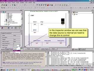
- 1. In the inspector window we can see that the data source is internal we need to change this to control
- 2. Change data source to control Help on data source in companion
- 5. Configure I/O set IP address
- 6. Add number of slots
- 7. Add modules to slot
- 9. From the tools folder we need to use the set IP address utility
- 12. We will now create a new Target that will hold our NIU configuration.
- 13. Configure the IP address we have already set and add the required modules
- 14. Right click here
- 15. Right click and configure the EBI
- 16. Double click here and enter IP address
- 17. Match these settings to your PC Red crosses mean we still have discrepancies and will not be able to download
- 18. Set to 1
- 19. Set to 1
- 20. Download configuration to NIU and power cycle the NIU
- 21. Drag from here To here Map our variables to our hardware
- 22. Select here Drag to here to include all new rungs Add a little more logic
- 23. Drop the highlighted logic to directly over the ladder element of our class
- 24. Download Project
- 25. Check feedback zone for download progress
- 26. We can see “Latch1” now reflects our changes
- 27. Grab parts from toolchest
- 28. See a preview of the part you want
- 29. Graphics may need transparency setting changed
- 30. Look into the property inspector
- 31. All navy elements are now transparent
- 33. Duplicate these pipes(right click) Drag and drop here
- 34. Double click rectangle set properties
- 35. Drag and drop all elements over the graphic in our toolchest
- 36. When we bring in a linked copy we are prompted for a name of our existing logic with which to associate it
- 37. Each tank is completely independent of the others
Editor's Notes
- Up until now all of our logic and graphics have been referenced to INTERNAL variables which is great for testing and commisioning but not much use for the REAL world
- We have changed the data source to Control but as yet have not specified the Control driver
- In the navigator window we select the control I/O driver icon
- As you can see we haven’t selected the I/O type as yet so you can develop the whole project with timers counters and PID loops etc and THEN select which manufacturers I/O you will use. We are using ethernet I/O
- Double click the newly created ethernet I/O driver. You will see the current default properties
- In the inspector window we can configure our I/O setup. Node number is ok, 2 slots, and change the address to match our network
- Select the slot and in the inspector window and the in the dropdown box select the module
- And again for slot 2. This configuration will be stored to our Logic controller on the PC
- We will temporarily set an IP address to enable our configuration to be stored to the NIU
- We need to enter the mac address and the required IP address
- It is all straight forward and is simply a tool that negates the need to know about TELNET and ARP commands
- Right click on the main rack icon
- There are one or two settings in the etherenet interface that need to put in correctly to enable save and download
- Enter the IP address
- Enter subnet mask these setting must match your network settings on your PC
- Set the produced and consumed exchanges to one
- After these are set the red crosses should disappear. We can now download. After downloading power cycle the NIU
- To map variables we simply drag from the variable inspector window onto the I/O map if you make an error right click and select unmap
- To add a bit more functionality we will add an up down counter CTUD you will as ever find all the information on how this works in the help simply by pressing F1 with CTUD element on the logic panel or by selcting help in the companion window or going to the help index
- After making these changes to the original element drop it in the toolbox directly onto the ladder element
- Download the project
- Download progress, warnings and errors shown the feedback zone
- You can now see our linked elements have been updated also. If we have a specific need for one switch to be attached to the same logic part in all of our linked objects we can use the universal variable this is denoted by the $ sign. You might want to include for instance an emergency stop button that applies to all circuits
- Let’s add some more graphics to represent our up down counter. Select the Home panel You can get graphics from the Machine Edition supplemental disk or from your own libraries to achieve aesthetically pleasing graphics we need to combine .bmps jpegs etc.. With ME animated objects. I have saved several parts to my toolchest
- The quick way is to drag and drop the parts on the panel
- Some appear a little odd but we can deal with that in a moment
- The motor pump graphic is showing a navy border to get rid of this simply go to the properties inspector window and set transparency to true and click on navy now all navy coloured parts will be transparent
- By dragging and resizing we can quickly mate up our individual parts send to back and front are useful to get the appearance just right There is a quick test feature that enables us to see how our panel will look without the need to download the complete project
- By duplicating the pipework I have ready made parts that just need placing I have added a round rectangle, even this has an entry in the help system, to the tank to show fill level
- By double clicking the round rectangle we can assign a variable through the animation properties window. Here I have assigned tank.cv which is the current value of the CTUD element. Here we set from 0% to 100% is equivalent to 0 to 3000 which is the counter preset in our logic
- Having completed our tank system we will place in the toolchest alongside our start stop panel directly over class name
- We now have original on the panel and we can in a similar way to the logic duplication bring in two linked copies which we will assign the offered structure names
- Now we can see each tank and start stop panel operating independently here Tank one is on and rising
- Tanks 1 and 2
- Finally Tanks 1,2 and 3 all running with linked logic and graphics but totally independent