CALIBRE’s exclusive, patented design mounts separate wireless radar receivers behind the front grill and rear bumper ~ strategically positioned for the fastest capture of radar signals. Distinct verbal or tone and visual alerts let you know exactly when and where to look for police.
With it's wireless & Datadyne technologies CALIBRE is simply the most powerful radar & laser protection system you can buy.
CALIBRE is also the only system you control with a hand-held remote, about the size of a key fob. And it's just as easy to use. With no permanently installed buttons to clutter your interior or to fuss with, you just click to select these modes: On/Off, City/Highway, Voice/Tone and Volume/Mute, then put your Wireless OneTouch™ Remote Control away until you want to change preferences.
More than Just Lines on a Map: Best Practices for U.S Bike Routes
Calibre Install Guide
1. Installation
Instructions
& Recommended
Procedures
The included CALIBRE Remote Control is used to allow the driver to adjust settings on the
CALIBRE and to mute audio alerts during prolonged encounters. It may be mounted virtually
anywhere inside the vehicle with the included double stick tape or remain unmounted.
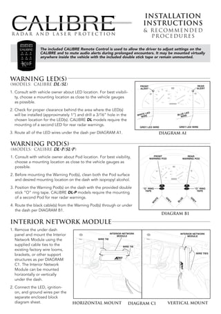
Warning LED(s)
FRONT REAR
ALERT ALERT
1. Consult with vehicle owner about LED location. For best visibili-
ty, choose a mounting location as close to the vehicle gauges
as possible.
2. Check for proper clearance behind the area where the LED(s)
E LED LED
will be installed (approximately 1”) and drill a 3/16” hole in the WHIT IRE BLUE E
W WIR
chosen location for the LED(s). CALIBRE DL models require the
mounting of a second LED for rear radar warnings. GREY LED WIRE
GREY LED WIRE
3. Route all of the LED wires under the dash per DIAGRAM A1. DIAGRAM A1
Warning Pod(s)
1. Consult with vehicle owner about Pod location. For best visibility, FRONT
WARNING POD
REAR
WARNING POD
choose a mounting location as close to the vehicle gauges as
possible.
2. Before mounting the Warning Pod(s), clean both the Pod surface
and desired mounting location on the dash with isopropyl alcohol.
3. Position the Warning Pod(s) on the dash with the provided double “O” RING “O” RING
TAPE TAPE
stick “O” ring tape. CALIBRE DL-P models require the mounting
of a second Pod for rear radar warnings.
G
UE
TE
G
R
R
HI
BL
EY
EY
W
4. Route the black cable(s) from the Warning Pod(s) through or under
the dash per DIAGRAM B1.
DIAGRAM B1
Interior Network Module
1. Remove the under dash
INTERIOR NETWORK
panel and mount the Interior MODULE
INTERIOR NETWORK
MODULE
Network Module using the WIRE TIE
supplied cable ties to the WIRE TIE
existing factory wire looms,
WIRE TIES
brackets, or other support
structures as per DIAGRAM
C1. The Interior Network
Module can be mounted
horizontally or vertically
under the dash.
2. Connect the LED, ignition-
on, and ground wires per the
separate enclosed block
diagram sheet. HORIZONTAL MOUNT DIAGRAM C1 VERTICAL MOUNT
2. Amplified Speaker
1. Route the amplified speaker cable around a panel
edge and reattach the under dash panel per
DIAGRAM D1.
2. For maximum audio output and concealment, DASH PANEL
mount the amplified speaker to the outside of the
SPEAKER
under dash panel with the supplied screws per SPEAKER
CABLE
DIAGRAM D1.
NOTE: If the vehicle is not equipped with an under
dash panel (e.g., Porsche), mount the ampli- SCREWS
fied speaker to existing factory wire looms,
brackets, or support structures with the
supplied cable ties.
DIAGRAM D1
Front Radar Receiver
1. Choose a mounting location in the front of the vehicle per DIAGRAM E1. The radar receiver can be mounted
horizontally or vertically provided the arrows are pointing forward, towards the road ahead.
2. Mount the front radar receiver with the supplied screws or wire ties to the vehicle’s structure per DIAGRAM E1.
3. Route the wires to the desired connection point and connect per the separate enclosed block diagram sheet.
NOTE: All radar receivers can be mounted behind plastic, rubber, or fiberglass up to 1/4” thick. Do not
mount radar receiver behind metal, carbon fiber or chromed plastic.
RADAR
RECEIVER
SELF-
TAPPING
SCREWS RADAR
RECEIVER
METAL SELF-
SUPPORT TAPPING
SCREWS
VERTICAL HORIZONTAL
MOUNT MOUNT
DIAGRAM E1
REAR RADAR RECEIVER
1. The rear radar receiver can be fastened to the vehicle using
the supplied self-tapping screws or cable ties. See DIAGRAM F1.
2. Route the rear radar receiver cable into trunk through factory
grommet.
3. If a factory grommet is not available, use the provided strain
relief:
a. Choose a location in the trunk compartment as close to
the radar receiver as possible. METAL
SUPPORT
b. Drill a 1/2” hole into the chosen location for the strain relief.
c. Install the strain relief and tighten the mounting nut securely.
d. Route the rear radar receiver cable through the strain RECEIVER
SCREWS
relief, leaving a little slack in the receiver cable.
e. Tighten the waterproof gasket nut to create a water- REAR RADAR RECEIVER
(BEHIND BUMPER COVER)
proof seal.
4. Connect wires per the separate enclosed block diagram sheet. DIAGRAM F1
44586-1 07/07
3. 1. The Calibre radar receivers are interchangeable. It’s the wire color code that differentiates
between front or rear radar. When you cut the cables to length, remember that the White wire
is battery power for the front receiver and the Blue wire is battery power for the rear receiver.
If the same color is used for both the front and the rear receivers only one receiver will be recognized.
2. Calibre radar receiver cables and EX Defuser cables should be cut to length. If the additional
wire is “balled up” it can act as an “RF” choke and cause operational anomalies.
3. Calibre radar receiver cables and EX Defuser cables are color-coded the same. The connections
are Brown to Brown, Yellow to Yellow, and Black to Black to Ground.
4. The ground wires on the Interior Network Module and the radar receivers should be connected
to an independent ground and not connected to a factory ground wire or lug.
5. The radar receivers and the Interior Network Module should never have their power wires or
ground wires connected to each other or to the same power or ground point.
6. The Interior Network Module must be connected to an isolated source of +12 Volt Ignition-on
and should not be connected in parallel with any other aftermarket accessory. Use of a factory
wire of less than 16ga requires an Ignition control relay.
7. The radar receivers should be connected to +12 volt battery power. A +12 volt Ignition-on
source is an option if battery power is not available.
8. Do not reset the Calibre system components when doing a new installation or a re-installation
of original components. A reset should only be done when a radar receiver or Interior Network
Module has been replaced. Replacement of a handheld remote or the addition of an EX
Defuser does not require that a reset be done.
9. Do not use any fuse larger that 1 amp for any components.
10. Use only Duracell AAAA batteries for replacement in the handheld remote control. Use of any
other brand batteries may result in erratic operation. Common signs that the batteries need
to be replaced are intermittent communication between the handheld remote control and the
Interior Network Module and pulsing or flashing remote control LED’s after a button press.
Any questions please call: 800.323.6768 24hr. Technical Support: 800.759.7243
Enter 55880 Press # and follow directions.