Graphs made easy with SAS ODS Graphics Designer (PAPER)

Graphs can provide the visual patterns and clarities that are not apparent in tables and listings, but sometimes it takes too long to create ones. Now, The ODS Graphics Designer makes it much easier. The paper is intended for Clinical Trial SAS® programmers who are interested in creating graphs using ODS Graphics Designer. The ODS Graphics Designer is a SAS/GRAPH GUI based interactive tool. The codes in ODS Graphics Designer are based on the Graph Template Language (GTL), but SAS programmers can create graphs using its point-and-click interaction without any programming. The ODS Graphics Designer allows SAS programmers to create many kinds of graphs such as scatter plots, series plots, step plot, histogram, box and more. The paper will show how to start the ODS Graphics Designer in SAS. The paper will also show how easy to create simple or complex graphs using the designer and how to enhance graphs using other features such as legends, cell properties, plot properties and so on. The paper will demonstrate how to create GTL and template codes from designer that will also create the exact graphs in SAS programming. The setting is set up in CDISC environment, so ADaM datasets will be used as source data.

Recommandé
Contenu connexe
Tendances
Tendances (10)
Similaire à Graphs made easy with SAS ODS Graphics Designer (PAPER)
Similaire à Graphs made easy with SAS ODS Graphics Designer (PAPER) (20)
Plus de Kevin Lee
Plus de Kevin Lee (20)
Dernier
Dernier (20)
Graphs made easy with SAS ODS Graphics Designer (PAPER)
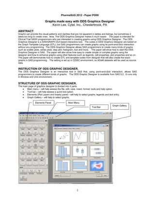
- 1. PharmaSUG 2012 - Paper PO09 Graphs made easy with ODS Graphics Designer Kevin Lee, Cytel, Inc., Chesterbrook, PA ABSTRACT Graphs can provide the visual patterns and clarities that are not apparent in tables and listings, but sometimes it takes too long to create ones. Now, The ODS Graphics Designer makes it much easier. The paper is intended for Clinical Trial SAS® programmers who are interested in creating graphs using ODS Graphics Designer. The ODS Graphics Designer is a SAS/GRAPH GUI based interactive tool. The codes in ODS Graphics Designer are based on the Graph Template Language (GTL), but SAS programmers can create graphs using its point-and-click interaction without any programming. The ODS Graphics Designer allows SAS programmers to create many kinds of graphs such as scatter plots, series plots, step plot, histogram, box and more. The paper will show how to start the ODS Graphics Designer in SAS. The paper will also show how easy to create simple or complex graphs using the designer and how to enhance graphs using other features such as legends, cell properties, plot properties and so on. The paper will demonstrate how to create GTL and template codes from designer that will also create the exact graphs in SAS programming. The setting is set up in CDISC environment, so ADaM datasets will be used as source data. INSTRUCTION OF ODS GRAPHIC DESIGNER. The ODS Graphics Designer is an interactive tool in SAS that, using point-and-click interaction, allows SAS programmers to create different kinds of graphs. The ODS Graphic Designer is available from SAS 9.2. It runs only in Window and Unix environment. STRUCTURE OF ODS GRAPHIC DESIGNER. The main page of graphics designer is divided into 4 parts. • Main menu – will help assess the file, edit, view, insert, format, tools and help option. • Tool bar – will help assess a quick tool option. • Elements (Plot Layers and Insets) panel – will help to select graphs, legends and text entry. • Graph Gallery – will help to select graphs. Elements Panel Main Menu Tool Bar 1 Graph Gallery
- 2. ADDITIONAL FUNCTIONALITY OF ODS GRAPHIC DESIGNER. The ODS Graphics Designer has many more functions. Once the graph is created, SAS programmers can right-click on the graph area and the additional functionality will be displayed. • Assign data o Select library and datasets in library o Variables Panel variables • Select column or row variables in data lattice and class variables in data panel Plot variables • Select x, y and group variables for plots • Plot Properties o Select inside color and outline of wall. o Select style element, color, pattern and thickness of lines o Select style element, color, symbol, size and weight of markets o Select the transparency of lines and markets • Axis Properties o Display label, value, grid and tick of axes o Display style element, color, font family, font size and font style of label and values in axes o Select color, pattern and thickness of grid in axes o Select type of plot(linear, log2, log10 and discrete), range of axes, tick sequence, reverse plots in axes. • Cell Contents o Remove the plots or move their positions to center, top and bottom of the graph. o Remove the plots or move their positions to center, top and bottom of the graph. • Add an Element – add plots, insets, titles or footnotes over the current graph • Add a Row – add another row of plots in the current graph • Add a Column – add another column of plots in the current graph • Remove a Row – remove a row of the plots • Remove a Column – remove a column of the plots • Move Row – move a row of the plots • Move Column – move a column of the plots • Graph Properties – modify the style, background(color and outline) and size(width and height) of the plots. Some of functions will be shown in below examples. HOW TO START ODS GRAPHICS DESIGNER There are two ways to create ODS Graphics Designer. After opening SAS session, • Select “Tools” and then select “ODS Graphics Designer” • Run macro statements of %sgdesign; or %sgdesign(); CREATE GRAPHS USING ODS GRAPHICS DESIGNER The paper will show examples of how some plots are created and enhanced using ODS Graphics Designer. Below are the examples of how some of graphs were created using ODS Graphics Designer. EXAMPLE 1 The example will show the comparison of mean PK concentration between two treatments over time points. 1. Prepare the work dataset of PKPD in SAS interactive environment. proc sql; **** the mean concentration and standard deviation range of PK; create table adpk as select trtpn, trtp, atptn, atpt, mean(aval) as mean_pk, std(aval) mean(aval)-std(aval) as lostd_pk, mean(aval)+std(aval) as from adam.adpk where pprotfl = 'Y' group by trtpn, trtp, atptn, atpt order by trtpn, trtp, atptn, atpt ; **** the mean concentration and standard deviation range of PD; create table adpd as select trtpn, trtp, atptn, atpt, mean(aval) as mean_pd, std(aval) mean(aval)-std(aval) as lostd_pd, mean(aval)+std(aval) as from adam.adpd where pprotfl = 'Y' group by trtpn, trtp, atptn, atpt order by trtpn, trtp, atptn, atpt ; quit; data pkpd; set adpk adpd; run; 2 as std, histd_pk as std, histd_pd
- 3. %sgdesign; 2. Run %SGDESIGN macro in SAS. ODS Graphic Designer splash screen is displayed, and then ODS Graphic Designer application interface will show immediately. ODS Graphic Designer Splash Screen ODS Graphic Designer Application Interface 3. Select Graph type (Here, Scatter plot) either in Graph Gallery or Plot Layers. Then, select WORK in “Library”, PKPD in “Data Set”, ATPTN (Analysis Time Point) in “X variable”, MEAN_PK(Mean Concentration of PK) in “Y variable”, and TRTP(Planned Treatment) in “Group variable”. 3
- 4. 4. We have a scatter plot graph below. 5. Click on View and then Code in main menu and now we can see Graph Template Language(GTL) codes. 6. Copy GTL codes and paste them into the SAS program editor window. The red-highlighted ones are GTL codes from ODS Graphic Designer. We can add more GTL codes for further customization. %macro graph; proc template; define statgraph sgdesign; dynamic _ATPTN _MEAN_PK _TRTP; begingraph; layout lattice _id='lattice' / columndatarange=data columngutter=10 rowdatarange=data rowgutter=10; layout overlay _id='overlay' /; seriesplot _id='series' x=_ATPTN y=_MEAN_PK / connectorder=xaxis group=_TRTP name='series'; endlayout; endlayout; endgraph; end; run; proc sgrender data=WORK.PKPD template=sgdesign; dynamic _ATPTN="ATPTN" _MEAN_PK="'MEAN_PK'n" _TRTP="TRTP"; run; %mend; **** ODS Graph Macro; %ODSGraph; 4
- 5. The macro %ODSGraph and style template could be set up so that SAS programmers can create graphs by simply copying and pasting GTL codes. SAS programmers also can customize the graphs further by adding more GTL codes. 7. It is recommended to set up the permanent style template. The permanent style template will be read by each graph program, so all the graphs are created in the same format. Below is an example of the style template macro that will create the permanent style template (i.e. templat.sas7bitm). The following codes are run in a separate SAS batch program. %macro template_GTL(font=Courier, height=1.25pct, heightg=8pt, path=C:study01Graph); *********************************************************************************; **** Create Style Template; *********************************************************************************; **** Prepare Graph Environment; options orientation=landscape missing="" nonumber nodate; libname myLib "&path"; ods path myLib.templat(update) sashelp.tmplmst(read); **** Set margins for RTF destination; proc template; define style myLib.chgRTF; parent = styles.rtf; style body from body / leftmargin = 1.0 in rightmargin = 1.0 in topmargin = 1.0 in bottommargin = 0 in ; replace GraphFonts / 'GraphDataFont' = ("&font",&heightg) 'GraphValueFont' = ("&font",&heightg) 'GraphLabelFont' = ("&font",&heightg) 'GraphFootnoteFont' = ("&font",&heightg) 'GraphTitleFont' = ("&font",&heightg) 'GraphUnicodefont' = ("&font",&heightg) 'GraphAnnoFont' = ("&font",&heightg) ; replace StatGraphFitLine / linethickness = 8px; style Graph from Graph / outputwidth = 9in outputheight = 6in; end; run; quit; %mend; %template_GTL; 8. The %ODSGraph macro sets up ODS settings for graphs, links to the style templates and saves the graphs in the permanent location. The %ODSGraph macro will call in %graph macro and create the graphs. %macro ODSGraph; **** Set up macro variables; %let path = C:study01Graph; %let font = Courier; **** ODS Option; ods trace on; ods listing close; libname myLib "&path"; ods path work.templat(update) myLib.templat(read) sashelp.tmplmst(read); ods graphics on ; ods rtf file="&path&pgm..doc" style=myLib.chgRTF bodytitle ; goptions reset=goptions device=png target=png ftext="&font" ftitle="&font"; ods noptitle; %graph; **** Closing ODS; options orientation=landscape ; ods path sashelp.tmplmst(read); ods rtf close; ods graphics off; ods listing; ods trace off; %mend; 5
- 6. EXAMPLE 2 We also have the ability to enhance the graph by adding standard error bars for the mean. show how to add additional graphs in the current graph. 1. This example will also After output has been created, right-click on graph and select “Plot properties” and click on “Markers” tab. We can see the changes (markers in each data point) in the graph immediately. 2. Right click on the graph screen and select “Add an Element…” 3. Select “Scatter” plots. 6
- 7. 4. Please note that “Library” and “Data Set” option was set to WORK and ADPK”. Now, select “X”, “Y” and “Group variables” (ATPTN, MEAN_PK and TRTP respectively) and click on “More Variables”. In “More Variables” window, assign “Y Error Upper” (HISTD_PK) and “Y Error Lower”(LOSTD_PK). 5. Hi and Low bars were added to the graph. After hi and low bars were created, we can rest your mouse to see what each point represents. EXAMPLE 3 Examples 1 and 2 discussed plots for Pharmacokinetic data. We also have the option of adding plots of pharmacodynamic data. This example will show how to add additional plots in the current graph and also how to add the legend and to modify axes. 1. Right click on the graph screen in the PK mean concentration plots and select “Add an Element…” 7
- 8. 2. Select “Series” plot. 3. Select “X”, “Y”, “Group variables” (ATPTN, MEAN_PD, TRTP) and select Y2 in “Axis”. Please note that this graph is called “series2”. 4. The PD mean concentration plots were added to the graph. The plots without the markers are a newly added PD mean concentration plots. 8
- 9. 5. We also have the option to apply markers to the newly added plots. Please note that the current graph has two plots and each plots’ property should be set separately, Click the PD mean concentration plots. 6. As previously explained, select “plot properties” and click on “Markers” tab. As shown below, markers were applied to PD concentration plots. 7. If we click “OK”, now we see both PK and PD mean concentration plots in the graph. 9
- 10. 8. In the current graph, we cannot really tell which one is PK or PD mean concentration plots, so let’s divide them using Y axes. First, right-click on right Y-axis. The right Y-axis is “Y2” axis. 9. Select “Advanced” tab and “Custom Axis Range”, then assign 0 to “Min” and 2 to “Max” in “Custom Axis Range” and 0 to “Start”, 1 to “End” and 0.5 to “Inc” in “Tick Sequence” for “Y2” axis. 10. Let’s do a similar modification on left Y axis. 10
- 11. 11. Let’s add a legend. Click “Discrete Legend” in “Insects” section and drag to anywhere we want in the graph. We can put the legend inside of graph, outside graph or anywhere in the graph. 12. Since we have two plots using the same groups in the graph, we have duplicate treatment groups. We can simply remove the duplicate ones by selecting only “series” in “Legend Contents” 13. After typing the title, footnote and label for the axes, the final graph is displayed below. 11
- 12. 14. We can also view the GTL codes for PK and PD mean concentration graph. BENEFITS The followings are the benefits of ODS Graphics Designer: • Very easy to use • Not much programming involved • Quick method to produce graphs • Interactive • Many different types of graphs can be done • Easy conversion to Graph Template Language(GTL) codes LIMITATIONS The followings are the limitations of ODS Graphics Designer. • Only one designer session can be open at a time. • Only a one page graph can be created. • Sometimes there are connection issues to the work library ( If there is a libref that points to a directory that does not exist, ODS Graphics Designer is unable to read the work directory) CONCLUSION As illustrated above, the ODS Graphics Designer is very easy to use. Both SAS programmers and statisticians can create graphs quickly and with very little SAS code. The benefits of ODS Graphic Designer definitely outweigh the few limitations. With the proper usage, SAS programmers can save a lot of time and effort for the creation of graph displays. REFERENCES SAS (R) 9.3 ODS Graphics Designer: User’s Guide CONTACT INFORMATION Your comments and questions are valued and welcomed. Please contact the author at Kevin Lee Cytel, Inc. Chesterbrook, PA (610) 994 - 9840 Email:Kevin.lee@cytel.com TRADEMARKS SAS and all other SAS Institute Inc. product or service names are registered trademarks or trademarks of SAS Institute Inc. in the USA and other countries. ® indicates USA registration. Other brand and product names are registered trademarks or trademarks of their respective companies. 12