Modern OpenGL Usage: Using Vertex Buffer Objects Well
•
21 likes•34,618 views

This tutorial explains how to use OpenGL vertex buffer objects (VBOs) well. Written in September 2008.

Recommended
Recommended
More Related Content
What's hot
What's hot (20)
Similar to Modern OpenGL Usage: Using Vertex Buffer Objects Well
Similar to Modern OpenGL Usage: Using Vertex Buffer Objects Well (20)
More from Mark Kilgard
More from Mark Kilgard (20)
Recently uploaded
Recently uploaded (20)
Modern OpenGL Usage: Using Vertex Buffer Objects Well
- 1. Modern OpenGL Usage: Using Vertex Buffer Objects Well Mark J. Kilgard NVIDIA Corporation Austin, Texas September 9, 2008 1 Introduction This whitepaper is a follow-up to an article titled Avoiding 16 Common OpenGL Pitfalls written back in 19981 for a course on OpenGL game development at the (then-named) Computer Game Developers Conference, now known as the Game Developer Conference (GDC). This new whitepaper focuses on what to do—instead of what to avoid—to get the most out of modern OpenGL implementations. OpenGL’s functionality has evolved remarkably since 1998. Back then, the OpenGL standard was just on the verge of supporting multi-texturing. Today’s GPUs shade vertices, primitives, and fragments all in 32-bit floating-point. OpenGL implementations available today expose all the features present in DirectX 10-class GPUs such as the GeForce 8. Back in 1998, I found OpenGL had a lot of programming pitfalls that novices stumbled over repeatedly. A decade later, there are thousands of experienced OpenGL programmers who know how to avoid OpenGL’s pitfalls, but these programmers still don’t always know the best ways to use OpenGL to get the best performance and quality from their GPU. So rather than focus on API pitfalls (I do mention a few along the way…), this whitepaper concentrates what to do to maximize your OpenGL application’s vertex transformation rate. The approach discussed is primarily through using vertex buffer objects efficiently and optimizing vertex index orders. 2 Maximizing Vertex Processing Rates To sustain the vertex transformation and primitive assembly rates of modern GPUs, high- performance OpenGL applications should store vertex attributes in vertex buffer objects and then assemble vertices by specifying vertex array indices. Vertex arrays stored in vertex buffer objects are in contrast to OpenGL’s original so-called immediate mode API 1 In an update in 2000, the original pitfall article was expanded from 16 to 19 pitfalls. Download the PDF from http://developer.nvidia.com/object/Avoiding_Common_ogl_Pitfalls.html 1
- 2. where vertex attributes such as colors, texture coordinate sets, and positions are specified one function call at a time using glColor4f, glTexCoord2fv, glVertex3f, etc. Vertex buffer objects have been part of core OpenGL since version 1.5. If you’ve not switched your application over to using vertex buffers, now is the time. Hopefully most OpenGL applications (surely yours, right?) have already switched over to vertex buffers for bulk vertex rendering. Still all advice should be taken in moderation. While sourcing vertex arrays stored in vertex buffers is crucial for attaining a GPU’s fastest vertex processing rates, the notion that an OpenGL application is “wrong” to ever use immediate mode is overzealous. The OpenGL 3.0 specification has even gone so far as to mark immediate mode in OpenGL for “deprecation” (whatever that means!); such extremism is counter-productive and foolish. The right way to encourage good API usage isn’t to try to deprecate or ban API usage, but rather educate developers about the right API usage for particular situations. The truth is that modern OpenGL implementations are highly tuned at processing immediate mode; there are many simple situations where immediate mode is more convenient and less overhead than configuring and using vertex arrays with buffer objects. 2.1 Immediate Mode versus Vertex Arrays If you are sending tens of thousands of vertices to render a complex model, sure, it certainly makes sense to use vertex arrays stored in vertex buffers. But if part of what your application does is interactively stretching a single, large shaded rectangle over the screen, there’s nothing wrong with immediate mode to render such a rectangle. Indeed, because immediate mode doesn’t require extra commands to enable and specify vertex arrays and there’s no coding to create, initialize, and bind vertex buffer objects, immediate mode winds up being easier to code, easier to debug, and roughly as fast— potentially faster—in rendering situations where you are rendering primitives with just a few vertices. Likewise, immediate mode commands can also be compiled into very efficient display lists which can surpass the performance of even carefully used vertex arrays in vertex buffer objects. 3 Start with Immediate Mode Let’s review how to use vertex arrays with vertex buffer objects. First let’s consider an immediate mode routine to draw a list of rectangles: 2
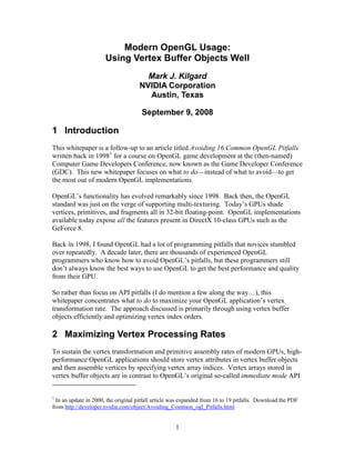
- 3. typedef struct { GLfloat x, y, width, height; GLfloat depth_order; GLfloat left_side_color[3]; // red, green, then blue GLfloat right_side_color[3]; // red, green, then blue } RectInfo; void drawRectangles(int count, const RectInfo *list) { glBegin(GL_QUADS); for (int i=0; i<count; i++) { const RectInfo *r = &list[i]; glColor3fv(r->left_side_color); glVertex3f(r->x, r->y, r->depth_order); glColor3fv(r->right_side_color); glVertex3f(r->x+r->width, r->y, r->depth_order); // right_side_color “sticks” glVertex3f(r->x+r->width, r->y+r->height, r->depth_order); glColor3fv(r->left_side_color); glVertex3f(r->x, r->y+r->height, r->depth_order); } glEnd(); } As shown in Figure 1, each rectangle has an (x,y) anchor position, a depth order (used as the rectangle’s depth for depth testing), width and height dimensions, and a left- and right-side color. The drawRectangles routine iterates over all the rectangles, drawing each as a quadrilateral (quad for short) with the appropriate left- and right-side colors assigned. left side color 1.0 right side color depth order height 0.0 (x,y) width Figure 1: Rectangle with its parameters. 3
- 4. 4 Convert to Conventional Vertex Arrays Let’s first convert the drawRectangle function to use vertex arrays instead of immediate mode commands. 4.1 Initializing Vertex Array Memory The initVarrayRectangles routine below allocates a buffer of system memory and initializes the memory with the same pattern of RGB and (x,y,z) vertex attributes as the immediate mode routine sends to OpenGL. void *initVarrayRectangles(int count, const RectInfo *list) { void *varray = (char*) malloc(sizeof(GLfloat)*6*4*count); GLfloat *p = varray; for (int i=0; i<count; i++, p+=24) { const RectInfo *r = &list[i]; // quad vertex #1 memcpy(&p[0], r->left_side_color, sizeof(GLfloat)*3); p[3] = r->x; p[4] = r->y; p[5] = r->depth_order; // quad vertex #2 memcpy(&p[6], r->right_side_color, sizeof(GLfloat)*3); p[9] = r->x+r->width; p[10] = r->y; p[11] = r->depth_order; // quad vertex #3 memcpy(&p[12], r->right_side_color, sizeof(GLfloat)*3); p[15] = r->x+r->width; p[16] = r->y+r->height; p[17] = r->depth_order; // quad vertex #4 memcpy(&p[18], r-> left_side_color, sizeof(GLfloat)*3); p[21] = r->x; p[22] = r->y+r->height; p[23] = r->depth_order; } return varray; } The system memory used to store the vertex arrays generated vertex attributes is just regular memory allocated from your process heap by malloc. This is memory belongs to your application’s process and is part of the process’s address space. The CPU can read and write this memory; but the GPU does not have unfettered access to your application’s address space and memory. When your application calls OpenGL commands, the OpenGL library passes data within your address space on to the GPU. The designers of OpenGL think of OpenGL as a sort of service for accessing the 3D rendering and imaging capabilities of graphics hardware. This is why OpenGL’s designers describe OpenGL as having client-server architecture. The client is your application and the server is the combination of the OpenGL library your application links with, an OpenGL driver residing in some combination of the operating system kernel and the window system, and the GPU. For this reason, the designers of OpenGL refer to your application’s address space and all the memory within it as client-memory. This memory includes your application’s global variables, its heap for dynamic memory allocations, its stack, and anything else mapped into its address space. By design, OpenGL accesses your application’s client memory only in direct response to your 4
- 5. application’s calling OpenGL commands and queries. Why I belabor this point will be clearer later and help you better appreciate the role of buffer objects in modern OpenGL programming. 4.2 Vertex Array Layout Figure 2 shows the layout of vertices initVarrayRectangles creates in memory. Each vertex requires 24 bytes (12 for color, 12 for position) so each independent quad requires 96 bytes of vertex attributes. float = 4 bytes red green color blue x vertex 0 y position z red green color blue x vertex 1 y position z Figure 2: Vertex array layout for rectangle list. Color and vertex attributes are interleaved. 4.3 Rendering with Conventional Vertex Arrays Now we can re-implement the drawRectangles routine so it initializes a system memory buffer with the appropriate vertex array data for the rectangles, configures OpenGL’s vertex array state to source the vertex attributes, and then draws the arrays: void drawVarrayRectangles(int count, const RectInfo *list) { char *varray = initVarrayRectangles(count, list); const GLfloat *p = (const GLfloat*) varray; const GLsizei stride = sizeof(GLfloat)*6; // 3 RGB floats, 3 XYZ floats glColorPointer(/*rgb*/3, GL_FLOAT, stride, p+0); glVertexPointer(/*xyz*/3, GL_FLOAT, stride, p+3); glEnableClientState(GL_COLOR_ARRAY); glEnableClientState(GL_VERTEX_ARRAY); glDrawArrays(GL_QUADS, /*firstIndex*/0, /*indexCount*/count*4); free(varray); } 5
- 6. Comparing the vertex array version to the immediate mode version, you’ll notice the vertex array version must allocate memory to store the entire set of rectangle vertex attributes. In contrast, the immediate mode version performs no memory allocation or de-allocation. If drawRectangles was used to render a just one rectangle, the immediate mode version is arguably more efficient since it would call 9 fast, simple OpenGL commands whereas the vertex array version calls 5 OpenGL state-configuration commands that involve reconfiguring and revalidating internal OpenGL state. This extra work is more involved than simply feeding vertex attributes, and then still has the burden of allocating, initializing, and de-allocating the vertex array memory. The point is that when we render enough rectangles—perhaps a dozen or more—the extra vertex array setup overhead is easily amortized over all the rectangles being processed. Something else not shown in the vertex array version of drawRectangles is that we are assuming that no other vertex arrays (for normal, texture coordinate sets, etc.) have been enabled. If so, we’d like to make additional glDisableClientState calls to disable these arrays. Using vertex arrays is more complicated because there’s a substantial amount of flexible state to first configure correctly. The immediate mode code has the benefit of being simpler, both to read and debug, if there are any problems. 4.4 Repeated Rendering from Vertex Arrays When we are rendering hundreds of rectangles, it’s no contest that the vertex array code is more efficient. When rendering hundreds of rectangles, amortizing the vertex array configuration overhead pays off well over all the rendered rectangles. The extra complexity of building the vertex buffer is justified by the more efficient communication of vertex attributes to OpenGL through a vertex array than a function call per vertex attribute with immediate mode. In the common situation where we render the same set of rectangles repeatedly, say once every window refresh, we can build the vertex array once with initVarrayRectangles and have a faster version of drawRectangles that expects the vertex array to be allocated and initialized. void drawInitializedVarrayRectangles(int count, const void *varray) { const GLfloat *p = (const GLfloat*) varray; const GLsizei stride = sizeof(GLfloat)*6; // 3 RGB floats, 3 XYZ floats glColorPointer(/*rgb*/3, GL_FLOAT, stride, p+0); glVertexPointer(/*xyz*/3, GL_FLOAT, stride, p+3); // Assume GL_COLOR_ARRAY and GL_VERTEX_ARRAY are already enabled! glDrawArrays(GL_QUADS, /*firstIndex*/0, /*indexCount*/count*4); } In the drawInitializedVarrayRectangles version of drawVarrayRectangles, we assume the varray parameter to be pre-initialized by a prior call to initVarrayRectangles. We also assume drawPreInitRectangles is not responsible for de-allocating varray. We also assume that the color and vertex arrays are already enabled. 6
- 7. 5 Motivation for Vertex Buffer Objects So far, we are sourcing vertex attributes through vertex arrays allocated in conventional system memory. The problem with conventional system memory is that the GPU doesn’t have arbitrary access to conventional system memory—remember this is the memory OpenGL designers call client-memory. So the OpenGL library must spoon-feed all the vertex attributes from system memory to the GPU when glDrawArrays is called. Rather than spoon-feeding the GPU, we’d really like to simply point the GPU at the vertex arrays and let the GPU read the vertex attributes from these arrays without the CPU having to be involved at all. This is hard with client-memory for a couple of reasons. First, the GPU runs asynchronously from the CPU running your application so there’s no easy way to arbitrate consistent access to your application’s address space and memory. Second, the GPU doesn’t, in general, have access to your application’s address space for lots of reasons including keeping the overall system operating robustly. The solution to this dilemma is storing vertex arrays in specially negotiated regions of memory maintained as OpenGL buffer objects that both your application and the OpenGL implementation can access and the OpenGL API can arbitrate a policy for consistent access to this memory. 5.1 GPU-accessible Buffer Objects With buffer objects, OpenGL can allow the GPU to source the vertex attributes directly where the GPU uses Direct Memory Access (DMA) to initiate the required memory read requests. Such DMA transfers are much more efficient than spoon-feeding vertex attributes in vertex arrays from conventional system memory to the GPU because the CPU is not involved in these DMA transfers. OpenGL allows such DMA transfers of vertex attributes when vertex array data is stored in what OpenGL calls a buffer object. Each buffer object in OpenGL is a range of contiguous untyped memory where the OpenGL implementation is allowed to configure the memory for use by the GPU. Both the GPU and CPU have access to the memory within a buffer object though OpenGL restricts how updates to the memory occur. There are commands to copy data to a buffer object and query data from a buffer object as well. An application can also map a buffer object into its address space (so-called client- memory from the OpenGL driver’s perspective), but a buffer object must be unmapped before the GPU can use it. Figure 3 and Figure 4 show the way vertex and command data flows when vertex arrays are sourced through client-memory and buffers objects respectively. 7
- 8. vertex application data travels command queue GPU transfer of (client) through command + vertex memory CPU data CPU writes of command + vertex command data processor vertex CPU vertex array puller hardware memory rendering reads pipeline CPU GPU Figure 3: Client-memory vertex array operation. All the vertex data typically ends up moving through the CPU in this mode of operation. application command queue GPU DMA transfer of (client) command data memory CPU writes of command + vertex command data processor Central vertex Processor puller hardware memory rendering OpenGL reads pipeline (vertex) buffer Graphics object Processor vertex GPU DMA transfer array of vertex data—CPU never touches data Figure 4: Client-memory vertex array operation. All the vertex data typically ends up moving through the CPU in this mode of operation. Calling the memory in a buffer object “untyped” means that the memory itself has no particular layout or format associated with it. Your application can place arbitrary words or bytes of memory within the buffer object. 5.2 Specifying Vertex Layout with a Buffer Object How the memory is interpreted depends on how OpenGL is told to access the memory. When you configure vertex arrays with the glVertexPointer, glColorPointer, etc. commands, your application is effectively telling OpenGL how to interpret the (otherwise untyped) data in a buffer object. 8
- 9. A buffer objects used to store vertex arrays is referred to as a Vertex Buffer Object or VBO for short. Buffer objects can be used for other purposes as well. For example, you can read or write pixel data from a buffer object. In this case, the buffer object is referred to as a Pixel Buffer Object or PBO for short. 5.3 Generic Nature of Buffer Objects While the terms VBO and PBO are handy jargon, please understand that there is nothing vertex-specific or pixel-specific about a given buffer object. A buffer object is described as a VBO if it is used to store vertex arrays; a buffer object is described as a PBO if it is used to read and write pixel data. When you create a buffer object, there’s nothing that forces a buffer object to be used only for pixels or only for vertices. In fact, a buffer object is just untyped memory that can be used for whatever usage OpenGL allows. Indeed, the ability to use an OpenGL buffer object any way you please is what makes buffer objects so powerful. Indeed, OpenGL 3.0 adds the ability to stream the results of vertex transformation into a buffer object. Other broadly-supported OpenGL extensions allow you to treat a buffer object as a special 1D texture object (the EXT_texture_buffer_object extension) or source parameters for an assembly shader directly from a buffer object (the NV_parameter_buffer_object extension), or source uniform values for a GLSL shader directly from a buffer object (the EXT_bindable_uniform extension). So when you use the terms VBO and PBO (or XBO, PaBO, BuBO for transform, parameter, and bindable uniform buffers respectively), keep in mind that you are describing your usage of the buffer but that description doesn’t require the buffer object to be used in that way only. A buffer object in OpenGL is a logically just a bucket of bytes (technically called the buffer’s data store) that the GPU knows how to directly access. A buffer object can be used as a VBO, PBO, XBO, PaBO, and BuBO and that may dictate how the bytes will be interpreted but the buffer’s data store itself is just bytes. Ultimately this makes buffers a very powerful, efficient, and central mechanism for transferring and converting data within OpenGL. 6 Using Vertex Buffer Objects Using vertex buffer objects is not much harder than using vertex arrays. The primary difference is the vertex attributes must be stored in the data store of a buffer object rather the client memory. 6.1 Vertex Buffer Initialization The API for establishing a buffer object is simple enough. Buffer objects are named by 32-bit values of type GLuint (like textures, display lists, and other OpenGL objects). The glBindBuffer command binds a named object to a buffer binding. GL_ARRAY_BUFFER is the buffer binding used for vertex arrays. If you bind a buffer name that has not been used before, the name is initialized to a zero-length buffer. Once bound to a buffer, the 9
- 10. glBufferData command initializes the currently bound buffer for the specified buffer binding with a specified number of bytes of data. The initial data is copied into the buffer object. The initVarrayRectanglesInVBO initializes a buffer object named bufferName to contain the vertex attributes for the rectangles. void initVarrayRectanglesInVBO(GLuint bufferName, int count, const RectInfo *list) { char *varray = initVarrayRectangles(count, list); const GLsizei stride = sizeof(GLfloat)*6; // 3 RGB floats, 3 XYZ floats const GLint numVertices = 4*count; const GLsizeiptr bufferSize = stride*numVertices; glBindBuffer(GL_ARRAY_BUFFER, bufferName); glBufferData(GL_ARRAY_BUFFER, bufferSize, varray, GL_STATIC_DRAW); free(varray); } Because the data is copied into the buffer object, initVarrayRectanglesInVBO can free the data allocated by initVarrayRectangle after calling glBufferData. The GL_STATIC_DRAW usage parameter to glBufferData indicates how the buffer is expected to be used. The static-draw usage means that the buffer’s contents are expected to be static and the data itself will be used for drawing operations (rather than reading or copying). Static usage means the data is expected to remain unchanged. Dynamic usage means random-access updates to the buffer’s data are likely. Stream usage means the data with in the buffer will be used a few times and then replaced with new data and this process will repeat. Buffer objects can be used in lots of different ways and their usage pattern may change with time. Setting the usage parameter reasonably when the buffer is first created assists the OpenGL implementation to provide a good initial placement, but the nine different usage parameters (the combinations of draw, read, and copy with static, dynamic, and stream) don’t capture all varied ways buffer objects can be used. The usage parameter is really an initial seed for how the buffer object will be used. You can expect that the OpenGL implementation will allocate the buffer to maximize performance for the buffer’s actual usage based on how the buffer is actually observed to be used. 10
- 11. 6.2 Drawing with Vertex Attributes from a Vertex Buffer Once we have a way to initialize a VBO with the vertex attributes, we need a version of drawRectangles to draw the rectangles from the data in the VBO. void drawVarrayRectanglesFromVBO(GLuint bufferName, int count) { const char *base = NULL; const GLsizei stride = sizeof(GLfloat)*6; // 3 RGB floats, 3 XYZ floats glBindBuffer(GL_ARRAY_BUFFER, bufferName); glColorPointer(/*rgb*/3, GL_FLOAT, stride, base+0*sizeof(GLfloat)); glVertexPointer(/*xyz*/3, GL_FLOAT, stride, base+3*sizeof(GLfloat)); // Assume GL_COLOR_ARRAY and GL_VERTEX_ARRAY are already enabled! glDrawArrays(GL_QUADS, /*firstIndex*/0, /*indexCount*/count*4); } The drawVarrayRectanglesFromVBO routine looks a lot like the prior drawPreInitRectangles routine with several crucial differences. First, drawRectanglesFromVBO has an extra initial parameter bufferName that names the buffer object with which to bind before configuring the color and vertex arrays. The bufferName parameter should be passed the same non-zero 32-bit integer name previously past to initVarrayRectanglesInVBO. 6.2.1 Latched Nature of the Vertex Array Buffer Binding State Something rather unapparent happens when your application calls glColorPointer, glVertexPointer, or any of the other vertex array specification commands. Every vertex array specification command latches the current GL_ARRAY_BUFFER buffer binding name as part of the vertex array state being specified. So when you call glColorPointer or glVertexPointer, you are specifying a number of components (3 in all the examples so far), an array type (GL_FLOAT in all the examples so far), a stride, and a vertex array base pointer—but you are also latching the current GL_ARRAY_BUFFER buffer binding for the vertex array as well. 6.2.2 Special Meaning of Zero for the Vertex Array Buffer Binding The initial GL_ARRAY_BUFFER buffer binding state is zero—or the non-buffer. When a vertex array is bound to the non-buffer (that is, when a vertex array specification command is issued and the non-buffer—named zero—is latched for that array), glArrayElement, glDrawElements, glDrawArrays, and similar routines read vertex attributes immediately from the vertex array’s base pointer with the appropriate offset based on the array’s number of components, type, and stride, and the draw command’s specified vertex index. The vertex data isn’t coming from a buffer object but rather your application’s address space. (This is all completely consistent with how vertex arrays operated prior to the introduction of vertex buffer objects in OpenGL 1.5.) 11
- 12. Now what happens when the latched buffer binding for a vertex array is not zero? In this case, the vertex attributes are not fetched immediately from your application’s client address space. Instead, the vertex attributes are fetched from the vertex array’s currently latched buffer object. The vertex array’s pointer is re-interpreted as an offset in bytes into the latched buffer object. The actual fetching of the vertex attributes from the buffer object doesn’t happen immediately but is deferred—allowing the GPU to use DMA transfers to read (or pull) the vertex attributes from the buffer object when the GPU actually receives the command to perform vertex pulling. There’s a pitfall here! If you are updating an application using client-memory (pre-VBO) vertex arrays, you may find when you start adding VBO rendering paths that your old client-memory vertex array paths appear to stop working. Consider what would happen if we executed the following code: static RectInfo rect_list[] = { { 20, 40, 50, 30, 0.5, { 1.0, 0.0, 0.0 }, { 0.0, 0.0, 1.0 } }, { 70, 50, 50, 30, 0.5, { 0.0, 1.0, 0.0 }, { 0.0, 0.0, 1.0 } }, }; const int rect_count = sizeof(rect_list)/sizeof(rect_list[0]); initVarrayRectanglesInVBO(/*VBO name*/27, rect_count, rect_list); // Yikes, GL_ARRAY_BUFFER left bound to 27! // XXX Assumes GL_ARRAY_BUFFER should be bound to zero so client-memory // (rather than a VBO) is sourced by glDrawArrays! drawVarrayRectangles(rect_count, rect_list); The comments help explain why drawVarrayRectangles is not going to render the triangles we expect. When initVarrayRectanglesInVBO initializes VBO 27, the OpenGL array buffer binding is left bound to VBO 27 when initVarrayRectanglesInVBO returns. Next when drawVarrayRectangles is called, the vertex array based pointers into client-memory passed to glColorPointer and glVertexPointer will be treated as byte offsets into VBO 27 rather than pointers in the application’s address space. Since pointers are usually large values, treating the pointers as offsets will generate very large offsets unlikely to be within the byte size of the VBO. Attempting to pull vertex attributes from beyond the end of a VBO results in undefined behavior. The likely result is that the vertex index that generated the vertex attribute offset beyond the buffer’s byte size will simply be ignored, but results including application instability or termination are possible. You can avoid this pitfall by making sure to bind the GL_ARRAY_BUFFER target to zero prior to any vertex array state configuration assuming vertices will be sourced from client-memory. The above example could be fixed as follows: initVarrayRectanglesInVBO(/*VBO name*/27, rect_count, rect_list); glBindBuffer(GL_ARRAY_BUFFER, 0); // Pull from client memory, not a VBO drawVarrayRectangles(rect_count, rect_list); 12
- 13. Safer still is to call glBindBuffer the array buffer to zero within drawVarrayRectangles. 6.2.3 Debugging Vertex Array Buffer Binding Issues Finally if you are having problems with VBOs in your application suspect a problem with vertex buffer object bindings, debug your situation by querying the vertex array binding state prior to calling glDrawArrays, glDrawElements, or other vertex array rendering commands. You might want to query the array sizes, types, strides, boolean enable, and pointer (treated as an offset when using buffer objects). Here’s code to query the array buffer binding (what glBindBuffer with the GL_ARRAY_BUFFER target changes) and the color and vertex array buffer bindings (what glColorPointer and glVertexPointer latch respectively): GLuint arrayBuffer, colorArrayVBO, positionArrayVBO; glGetIntegerv(GL_ARRAY_BUFFER_BINDING, &arrayBuffer); glGetIntegerv(GL_COLOR_ARRAY_BUFFER_BINDING, &colorArrayVBO); glGetIntegerv(GL_VERTEX_ARRAY_BUFFER_BINDING, &vertexArrayVBO); Notice there’s one overall array buffer binding, but each individual array (color, vertex, etc.) has its own latched version of the array buffer binding. This example reinforces the way the array buffer bindings are latched: glBindBuffer(GL_ARRAY_BUFFER, 1992); glColorPointer(3, GL_FLOAT, /*stride*/24, /*offset*/((char*)0)+0); glVertexPointer(3, GL_FLOAT, /*stride*/24, /*offset*/((char*)0)+24); glGetIntegerv(GL_ARRAY_BUFFER_BINDING, &arrayBuffer); glGetIntegerv(GL_COLOR_ARRAY_BUFFER_BINDING, &colorArrayVBO); glGetIntegerv(GL_VERTEX_ARRAY_BUFFER_BINDING, &vertexArrayVBO); assert(arrayBuffer == 1992); assert(colorArrayVBO == 1992); assert(vertexArrayVBO == 1992); glBindBuffer(GL_ARRAY_BUFFER, 2008); glGetIntegerv(GL_ARRAY_BUFFER_BINDING, &arrayBuffer); glGetIntegerv(GL_COLOR_ARRAY_BUFFER_BINDING, &colorArrayVBO); glGetIntegerv(GL_VERTEX_ARRAY_BUFFER_BINDING, &vertexArrayVBO); assert(arrayBuffer == 2008); assert(colorArrayVBO == 1992); assert(vertexArrayVBO == 1992); glVertexPointer(3, GL_FLOAT, /*stride*/12, /*offset*/((char*)0)+0); glGetIntegerv(GL_ARRAY_BUFFER_BINDING, &arrayBuffer); glGetIntegerv(GL_COLOR_ARRAY_BUFFER_BINDING, &colorArrayVBO); glGetIntegerv(GL_VERTEX_ARRAY_BUFFER_BINDING, &vertexArrayVBO); assert(arrayBuffer == 2008); assert(colorArrayVBO == 1992); assert(vertexArrayVBO == 2008); Notice how binding the GL_ARRAY_BUFFER target to a different buffer object (from 1992 to 2008) doesn’t change the color and vertex array buffer binding—just the 13
- 14. GL_ARRAY_BUFFER_BINDING state changes. Yet once the array buffer target is changed to 2008, then the glVertexPointer command latches this updated value when glVertexPointer is called the second time. 6.3 Benefits of Using Vertex Buffer Objects Because the vertex pulling is done by the GPU using efficient DMA transfers, the CPU doesn’t have to move each vertex attribute through its registers and cache. So your application spends less CPU cycles within the OpenGL driver and your CPU’s cache doesn’t have to be “polluted” with vertex attributes intended for transformation by the GPU. In our rectangle rendering example, both the vertex position and color arrays are pulled from the same buffer object. That doesn’t have to be the case. Each array of vertex attributes can be pulled from its own buffer object. This would be the case in the above example where the color array buffer binding is left bound to 1992 while the vertex array buffer binding for position is left bound to 2008. 6.3.1 Interleaved versus Separate Arrays When each individual vertex arrays is kept in its own packed range of buffer or client memory, we refer to this vertex array configuration as separate arrays. The other case is interleaved arrays where different arrays are arranged so each vertex has its various vertex attributes packed together. OpenGL is very flexible in how vertex arrays are configured. Vertex arrays can be separate but still residing in the same buffer object, or the arrays can reside into different buffer objects. If two or more arrays are interleaved, that implies the vertex arrays are all in the same buffer. For good performance, you should make sure that if you use VBOs to render a set of vertices, you want all the vertex arrays to be stored in VBOs. Technically, OpenGL allows you to have some vertex arrays kept in client-memory (their buffer array binding would be latched to zero) and other arrays could pull vertices from VBOs. This isn’t a good combination because the CPU will still be required to feed the vertex attributes found in the client-memory arrays. That ends up defeating the benefits of DMA vertex pulling by the GPU. This situation may even be worse than simply having all your vertex arrays in client-memory. So when rendering a given object, make sure all your vertex arrays are either all pulling from VBOs or all pulling from client-memory. For good performance, go not mix the streams! 6.3.2 Vertex Buffer Cache In order to increase the efficiency of the GPU when pulling vertex attributes from vertex buffer objects, the GPU keeps a cache of recently pulled vertex buffer cache lines. If you vertex attributes are packed tightly together, that makes this caching more effective. This cache is hashed by cache line offset within each buffer. 14
- 15. If you randomize the order of your vertex indices, that may lead to poor vertex buffer caching. When you can, try to arrange indices so that the vertex attributes fetched by these indices are likely to have reasonable locality within the vertex buffer object. 6.3.3 Vertex Index Reuse Modern GPUs also optimize the case when a recently transformed vertex index is re-used in the sequence of vertex indices defining the primitive set to render. For example, when rendering meshes of triangles, it is common to send the same vertex index multiple times because the vertex may belong to several different triangles. A single vertex in a triangle mesh commonly belongs to six or more primitives. Figure 5 shows an example of such a shared vertex within a triangle mesh. B A C F D E Figure 5: Portion of a triangle mesh where a single central vertex is shared among the triangles A through F. The other vertices in the mesh are shared among other triangles as well. When a given vertex index that has recently been transformed is re-specified in the sequence of vertex indices specifying a batch of geometry primitives (triangles, quads, or lines), the GPU can simply re-use the prior transform result for the vertex. The GPU does this by maintaining a cache of post-transformed vertices, hashed by vertex index. 7 Optimizing Vertex Index Reuse When you use glDrawElements to send a list of indices, order the indices to maximize the locality of reused vertex indices. Generally when you are rendering opaque objects with depth testing for hidden surface elimination, the exact order of vertex indices (this order is often called object order) does not materially affect the resulting rendering. For this reason, it makes sense to optimize your vertex index ordering to maximize the GPU’s hit rate in the post-transform vertex cache. Each time the GPU can find a given vertex index already transformed, that saves all the instructions necessary to re-shade that vertex. This can be a substantial savings of shading effort. Not only is shading effort saved, you can also save bandwidth because vertex attributes for a vertex index found in the post-transformed vertex cache do not need to be fetched into the GPU again. 15
- 16. 7.1 Cache Oblivious Vertex Index Reuse Optimization You do not need to know the number of transformed vertices that GPU keeps in its post- transform cache. You can use so-called cache oblivious strategies so you get high vertex index reuse no matter the cache size. This is good because different GPUs, particularly different generations, have different post-transform cache size. Also the effective size of the post-transform cache can depend on the number of vertex attribute components you vertex shader outputs. The more vertex attribute components your vertex shader outputs, the more storage is required to maintain each post-transformed vertex. The granularity of this trade-off depends on the GPU architecture. So what strategy should you use to order your vertex indices? You want to perform an optimization pass on your vertex index lists. The cache oblivious approach assigns a likelihood that each vertex is in the post-transform vertex cache. Initially all vertex indices would have likelihood of 0.0 for being in the cache. Immediately after a vertex index has been transformed, the vertex has a likelihood of 1.0 (the highest probability). While the actual hardware is typically deterministic about how its post-transform vertex cache operates, we think about our algorithm in probabilistic terms, not because the hardware is random, but rather because we are uncertain—or really do not want to assume—how a particular GPU’s post-transform vertex cache operates. But we want to assume that recently transformed vertices have a higher likelihood of being in the cache than vertices that have never been transformed or transformed long ago. Each time we transform a new vertex, we multiply the probability of all vertex vertices by a certain percentage (say 95%). So the vertex just transformed has a 0.95 likelihood of being in the cache now that a subsequent vertex has been transformed. That newly transformed vertex has its likelihood set to 1.0. If we see a vertex index repeated, we assume the hardware keeps that vertex around (it may be used yet again) so we post that re-used vertex’s likelihood. Rather than model a particular GPU’s particular algorithm for maintaining post- transformed vertices in its cache, we make broad assumptions that more recently used vertices are more likely to be found in the cache. With these assumptions, we can attempt to pick a vertex index order for a given model or batch of vertices that maximizes the probability that the next vertex index in a given batch of vertex indices has the best change of being found already transformed in the post-vertex cache. 7.2 Complexities of Vertex Distribution in Modern GPUs In more recent GPU architectures, vertex sub-batches are distributed among multiple unified shading units. Think of this like families trying to go through customs at the airport. There are some fixed number of (say 8) custom agents (think: shader unit), but each family (think: geometric primitive such as a triangle) consists of a set of individuals (think: each is a vertex index). Each family must be processed completely by a given custom agent. Basically, custom agents are not allowed to split up families being processed. 16
- 17. This rule about not splitting up families is useful when, instead of custom agents, families, and individuals, we are talking about shader units, geometric primitives, and vertex indices. In the case of the three vertices that make up a triangle, the rule means two vertices cannot be sent to one shader unit and the third sent to a different shader unit because that would be too complex to later re-assemble the transformed vertices back into a triangle. It is simpler just to keep all three vertices together as a unit. Where our custom agent analogy breaks down is when we consider that vertex indices can belong to multiple geometric primitives (as shown in Figure 5). It is not likely that a single individual would belong to two or more families while going through customs, but that analogous situation happens all the time with indexed meshes of polygons. And the situation is not simply that a single vertex belongs to n primitives; the problem is more complex because other vertices that belong to those n primitives belong to a different set of other primitives. Sometimes the GPU simply will be required to split a batch of vertices across multiple shader units. Otherwise, one shader unit might end up responsible for all the interconnected vertices and the other shader units would be left idle. A vertex that belongs to primitives that are split between two shader units gets replicated. Essentially there is a duplicate version of the vertex sent to each shader unit that is processing other vertices that belong to the duplicated vertex’s primitives. When a vertex gets duplicated in this way, each shader unit will re-transform the vertex. While this duplicates a small amount of work, it allows lots of shader units to operate in parallel on the stream of vertices. GPU designers are willing to tolerate a small amount of redundant work for the more substantial benefit of being able to process more vertices in parallel. One way to deal with this problem is to have each shader unit in turn get dolled out a large chunk of vertex indices. Think of the hardware as having a smart distributor that doles out these large chunks to the multiple shader units. Within each large chunk, the chuck’s assigned shader unit identifies redundant vertex indices in the large chunk’s index stream and then combines sets of unique vertices each into a group (what NVIDIA calls a warp) so the group can be processed as a hardware-efficient batch (say 16 or 32 vertices at a time) of vertex shading work. When these large chunks of vertices are dolled out to the set of available shader units, vertex indices may have to be duplicated when switching from one shader unit to another. In such a scheme involving a set of distributed shader units within the GPU, each shader unit can maintain its own cache of post-transformed vertices. Different GPU designs may have different numbers of shader units. This all gets very complex. This is why it really makes sense to adopt a cache-oblivious probabilistic approach to optimizing vertex index ordering. The other reason is that a somewhat improved vertex order is much better than a non-optimized order, but the “perfect” vertex order is not that much better than the close-enough-to-perfect ordering a cache-oblivious probabilistic strategy can generate. 17
- 18. Things can get still more complicated if you let them. 7.3 View-dependent Vertex Index Ordering Optimization Two vertex index orderings may both achieve a comparable level of vertex reuse but one of the orderings could still be measurably faster than the other one because of view- dependent vertex order differences that allows for better fragment-level culling. 7.3.1 Fast Fragment-level Culling Modern GPUs perform optimizations that efficiently cull rasterized fragments if the GPU can “prove” that the fragment is destined to be eliminated by the depth test. One approach known as early Z is simple enough. Before the shader runs for a given fragment, perform the depth test and if the fragment would fail the depth test, cull the fragment immediately and do not spend any effort executing the fragment’s corresponding shader. In a variation on the early Z technique, which NVIDIA calls Zcull, the GPU can maintain an on-chip compressed and conservative version of the depth buffer. With Zcull, an entire tile of fragments may be able to be eliminated without even reading the actual depth values for the covered pixels. This allows whole tiles pixels (often 16 pixels in a 4x4 arrangement) to be culled at once. When multisampling is in operation, there are multiple samplers per pixel so a large number of samples can be eliminated. With 4x multisampling, a tile would contain 64 logical samples. 7.3.2 Limitations of Early Depth Testing There are some situations such as alpha testing or when a fragment shader computes its own depth value or when depth testing modes are modified when early Z and Zcull cannot be enabled, but generally these optimizations greatly improve the performance of the GPU with absolutely no difference to the rendered scene. 7.3.3 Favoring Front-to-Back Rendering You can get the most benefit from early Z and Zcull if your application can choose to approximately render the geometric primitives in your scene approximately from front to back. By rendering front-most primitives first, we stand the best chance that subsequent primitives will be behind those front-most primitives and benefit from early Z and Zcull. The problem is that the orientation of a given object with respect to the view may change as the scene animates. Which vertex index ordering most perfectly renders the scene front-to-back depends on the view. Rather than attempt to pick the optimal vertex order for any given view of an object, we can settle for keeping a small number of discrete vertex index orders, perhaps one for each face of the cube—so six vertex orderings. Then the application could select what vertex index ordering to use based on which cube direction was most coincident with the actual current view. 18
- 19. These multiple view-dependent vertex index orderings would also be simultaneously optimized for good post-transform vertex cache behavior. Whether your application would actually observe a speed-up from any of the techniques described really depends on several factors. First, if you application is CPU-limited, it really does not matter how efficient you make your GPU usage since the GPU is not your bottleneck. Optimized vertex index ordering can be a substantial improvement in performance because it avoids redundant vertex transformations, but vertex transformation has to be a substantial portion of your rendering load for this to matter. How important view-dependent vertex index order is depends on the actual opportunity for early Z and Zcull possible. The view-dependent vertex order shines when the fragment shader is very long and complex so culling fragments early is a big win. Keeping multiple sets of view-dependent vertex indices also takes up memory. Given the extra memory required for multiplex index lists and the complexity of view-dependent vertex index orderings, view-dependent vertex orders may not be worth the effort. 8 Priority Scale of Vertex Optimizations While it is useful to know that vertex index order can make a real difference in your rendering performance, when you are optimizing your OpenGL rendering performance you should always be careful to reap low-hanging fruit first. Here is a checklist of optimization advice to improve your vertex transformation rate— and hopefully overall rendering rate too. 1. Use vertex arrays stored in vertex buffer objects 2. Check that there is no vertex arrays enabled that your vertex shader does not use. You don’t want the hardware reading vertex attributes you don’t actually need. 3. Review your vertex shader and see if you can write it more efficiently. 4. Generate a cache oblivious vertex index order for your 3D models. 5. Arrange your indexing scheme for your vertex arrays to maximize the pre- transform cache. 6. Use the NV_primitive_restart extension to minimize the number of indices your application must send. Independent triangles require two to almost three times the vertex indices as triangle strips used with primitive restarts. 7. See if view-dependent vertex index orders improve performance. The general rule of thumb with this list is do not try something further down on the list when you have not yet exhausted things earlier on the list. 9 Conclusions If you are sending a lot of vertices to OpenGL, please use vertex arrays. If you are rendering from indexed vertex arrays, consider if a better vertex index order would improve performance. 19