Mattingly "AI & Prompt Design: The Basics of Prompt Design"
Paper on IEC 61850
1. 1
The IEC 61850 Standard an intelligent application in Substation &
Automation system
Mohan Vinayak Sawarkar 1. Mohini Mohan Sawarkar 2.
1.
Bharati Vidyapeeth Institute of Technology, Navi Mumbai.
Lecturer- Electrical mohansawarkar@gmail.com
2.
Bharati Vidyapeeth College of Engineering, Navi Mumbai.
Asst. Professor- Electrical mohini1nov@yahoo.co.in
ABSTRACT
As industrial economies grow and become more efficient they also become more reliable on electricity as their main
source of energy. Hence, a blackout in electrical system causes massive damage to social and economic aspects of a
society. To prevent interruptions and to provide energy to electricity consumers reliably automation needs to take
place at each stage of the electrical system: generation, transmission, and distribution. As each stage is automated,
there has to be reliable, fast, and efficient communication amongst devices and the SCADA control center.
Communication lines need to carry information and data between substations and control centers at different parts of
the network so that monitoring and automation of the system can occur. Without adequate communication amongst
devices SCADA system will render itself useless and will not be able to provide the reliability and efficiency needed
in today‟s electricity markets. It is also important to note that automation in electrical systems allows for the system
control and operator to define specific performance and protection parameters, which will lead to consistency across
the electrical grid. Legacy substation automation protocols and architectures typically provided basic functionality
for power system automation and were designed to accommodate the technical limitations of the networking
technology available for implementation. IEC61850 is an important new international standard for substation
automation that will have a very significant impact on how electric power systems are designed and built for many
years to come.
COMMUNICATION SYSTEM NEEDS.
Consequently, a key component of a communication system is the ability to describe themselves from both a data
and services (communication functions that an IED performs) perspective. Other “key” requirements include:
· High-speed IED to IED communication
· Networkable throughout the utility enterprise
· High-availability
· Guaranteed delivery times
· Standards based
· Multi-vendor interoperability
· Support for Voltage and Current samples data
· Support for File Transfer
· Auto-configurable / configuration support
· Support for security
COMMUNICATION NETWORK
A network is an interconnected system of electronic devices which share information with each other. A network
provides the media in which the information is transferred from one location to another. It is also the vein or
bloodline of any SCADA system, so its speed, reliability, and efficiency are absolutely crucial. There are many
types of networks, but only two types apply to substation environments and power systems: Serial-based and
Ethernet-based. Ethernet-based systems in power systems are also referred to as Integrated Substation Control
Systems (iSCS). There are many standards for each type of networks; however, in substation automation RS-232
2. 2
(point-to-point links) and RS-485 (multi-drop links) in serial networks and IEEE 802.3 in Ethernet systems are the
most common.
PROTOCOL
A protocol is a set of formal rules describing how to transmit data across a network. The rules could be low-level,
which define the electrical and physical standards to be observed, bit- and byte-ordering and the transmission and
error detection and correction of the bit stream. In this section the high-level protocols will be discussed which
describe the data formatting, including the syntax of messages, character sets, and sequencing of messages. In short,
a protocol is a predefined digital language. The need for a protocol is quite apparent. In any power system there are
many devices from different countries and made by different manufacturers which perform different tasks in
SCADA. In order to create a communication network a common „language‟ or protocol is needed.
GENERAL PROPERTIES OF PROTOCOL
a) Network compatibility – some protocols have only been defined to operate in serial networks such as
Conitel. On the other hand, some protocols have been defined to work both on Ethernet and Serial systems such as
DNP 3.0
b) Speed – the speed at which a protocol transfers information amongst multiple devices is a very important
measure of its performance.
c) Reliability – the transfer of information has to be reliable. Some protocols may have checks in place to ensure
proper communication of messages. The level of reliability is another important measure of a protocol‟s
performance.
d) Expandability – protocols need to be able to handle small, medium, and large systems in SCADA. For
example, DNP 3.0 is able to handle very large system with over 65,000 data objects, whereas, Conitel or
Cooper protocols will not handle such large amounts of information well.
e) Security – in today‟s information age the security of information has to be ensured or else information may be
hacked or hampered during its transfer through the network. The protocol‟s level of security and encryption of data
are important issues in power systems.
f) Acceptability – a protocol needs to be accepted in the power industry and by the equipment manufacturers.
Protocols that are unique to specific manufacturers and are proprietary cannot be the common „language‟ in a
SCADA system. When choosing a protocol one needs to determine
whether all the components of the power system are able to communicate in that specific protocol or not.
g) Simplicity – It is important for a protocol to be simple so that its users can configure and maintain SCADA
systems easily and without the need for special expertise. The number of features and functionalities should be
limited to provide an economic solution for manufacturers and consumers.
h) Consistency – a protocol has to be controlled and standardized by one committee in the world to provide
consistency.
i) Functionality – a protocol should have all the features and functions used in SCADA such as time
synchronization and file transfer.
j) Economics – a protocol should be economic as its costs will determine its future in power systems.
IEC 61850 MODELLING APPROACH
Legacy protocols have typically defined how bytes are transmitted on the wire. However, they did not specify how
data should be organized in devices in terms of the application. This approach requires power system engineers to
manually configure objects and map them to power system variables and low-level register numbers, index numbers,
I/O modules, etc. IEC 61850 is unique. In addition to the specification of the protocol elements (how bytes are
transmitted on the wire), IEC 61850 provides a comprehensive model for how power system devices should
organize data in a manner that is consistent across all types and brands of devices. This eliminates much of the
tedious non-power system configuration effort because the devices can configure themselves..
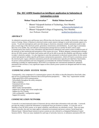
3. 3
The IEC 61850 device model begins with a physical device. A physical device is the device that connects
to the network. The physical device is typically defined by its network address. Within each physical
device, there may be one or more logical devices.
Each logical device contains one or more logical nodes. A Logical node is a named grouping of data and
associated services that is logically related to some power stem function. There are logical nodes for
automatic control names of which all begin with the letter “A”. There are Logical nodes for metering and
measurement the names of which all begin with the letter “M”. Likewise there are logical nodes for
Supervisory Control (C), Generic Functions (G), Interfacing/Archiving (I), System logical nodes (L),
Protection (P), Protection Related (R), Sensors (S), Instrument Transformers (T), Switchgear (X), Power
Transformers (Y), and Other Equipment (Z).. The standard Name of the Logical node for a Measurement
Unit for 3-phase power is MMXU.
Each element of data within the logical node conforms to the specification of a common data class (CDC)
per IEC 61850-7-3. Each CDC describes the type and structure of the data within the logical node. Each
CDC has a defined name and a set of CDC attributes each with a defined name, defined type, and specific
purpose.
Each individual attribute of a CDC belongs to a set of functional constraints (FC) that groups the attributes
into categories
Fig.1 The object model of IEC 61850
PROCESS BUS:
When we are talking about a process bus in the context of IEC 61850, we are going one step further with the
introduction of communication technology in a substation automation system. In a traditional approach, a substation
automation system consists of multiple intelligent electronic devices (IED) like protection relays and bay control
devices. These devices are connected to each other and to the substation gateway and local HMI through a
communication network. Since that communication network connects all the devices of a substation, it is typically
called station bus. An example is shown in Figure
Fig.2 Example of a substation automation system with a station bus
4. 4
Fig.3 Example with process bus
With current and voltage transformers, the situation is similar. A typical interface here is what is called “Merging
Unit” as shown in Figure. A merging unit provides a set of samples of the analogue signal to the communication
network. Typically a merging unit will provide synchronized samples from the three phase currents and the three
phase voltages. If conventional CTs and VTs are used, the merging unit will do the analogue to digital conversion of
the conventional output of the CTs and VTs. If non conventional sensors like optical sensors are used, the merging
unit will be integrated in the electronics required to process the optical
signal.
Fig. 4 Concept of a merging unit
Features are offered by the standard:
- The possibility to put a function or a functional element in test mode. IEC
61850 provides the possibility to put logical nodes or logical devices in a test
mode.
- The possibility to characterize a GOOSE message as a message being sent for
test purpose.
- The possibility to characterize a service of the control model as being sent for
test purpose.
- The possibility to flag any value sent from a server in the quality as a value for
test purpose.
- The possibility to substitute a value.
5. 5
Conclusion
A substation automation system including an IEC 61850 based Process bus offers several benefits to the
user. As an overall consequence of the benefits, life cycle costs of a substation will be reduced
The features of IEC 61850 show its power for introducing new intelligent applications being more complex
and efficient for the power system management, system stability and asset management.
IEC 61850 is a high-level communication standard with a lot of additional features regarding functions and
engineering. It comprises the know-how of many engineers worldwide in the areas of communication,
substations and substation automation including protection.
References
1) Technical discussions with testing teams of MSETCL‟s 400 KV Kharghar substation.
2) www.siemens.com
3) www.abb.com
4) www.areva-td.com