10 Best WordPress Plugins to make the website effective in 2024
Thomas screw conveyor design
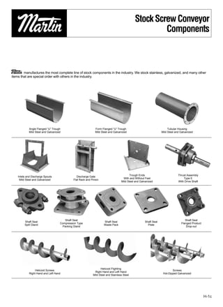
1. Stock Screw Conveyor
Components
Martin manufactures the most complete line of stock components in the industry. We stock stainless, galvanized, and many other
items that are special order with others in the industry.
Angle Flanged “U” Trough Form Flanged “U” Trough Tubular Housing
Mild Steel and Galvanized Mild Steel and Galvanized Mild Steel and Galvanized
Trough Ends Thrust Assembly
Inlets and Discharge Spouts Discharge Gate
With and Without Feet Type E
Mild Steel and Galvanized Flat Rack and Pinion
Mild Steel and Galvanized With Drive Shaft
Shaft Seal Shaft Seal
Shaft Seal Shaft Seal Shaft Seal
Compression Type Flanged Product
Split Gland Waste Pack Plate
Packing Gland Drop-out
Helicoid Flighting
Helicoid Screws Screws
Right Hand and Left Hand
Right Hand and Left Hand Hot-Dipped Galvanized
Mild Steel and Stainless Steel
H-1c
2. Stock Screw Conveyor
Components
Tail, Coupling
Sectional Flights
and Drive Shafts
Hanger Hanger
Style 220 Style 226 Hanger Hanger Hanger
Mild Steel and Mild Steel and Style 216 Style 70 Style 19B
Galvanized Galvanized
Hanger Bearings
Style 220/226
Hanger Bearings Trough End Bearings Saddles and Feet
Martin Hard Iron Style 216 Ball and Roller
Martin Bronze Hard Iron
UHMW
UHMW Wood
Nylatron®
Wood
Shaft-Mounted
Screw Conveyor Drive Flanged Cover
Speed Reducer
with Accessories with Accessories
with Accessories
H-1d
3. Made-To-Order
Conveyors
Stainless Steel Rotor 60 Inch Diameter Stainless Steel
After Shot Peening. Used in the Bleaching Steaming Vessel Screw Used in
Process in a Pulp & Paper Mill. Handling Wood Chips.
Rotory Screen Separator Special Offset Stainless Steel Hanger Elevator Buckets
For Making Commercial Ice. Used in Handling Various Chemicals.
USDA Approved Stainless Steel Test Facility. an Added Customer Service.
Screw Conveyor for Handling This Area is Available to Check the Conveying
Hamburger Meat in a Food Characteristics of Customers’ Materials.
Processing Plant.
*Conveyors showh without cover for illustration purposes only. Please follow manufacturing safety guidelines when operating conveyors. H-1e
4. Special Tolerance
Requirements
Our association with research and development personnel,
plant engineers and food specialists has offered the
challenge to Martin to meet industry’s new close toler-
ances. Here are but a few examples of manufacturing tech-
niques that we practice.
Dynamic/static balancing of screws takes place at one of Martin’s manufacturing facilities. Inspecting total indicated runout of vertical screws.
Stainless steel screw conveyor unit for breakfast cereal plant is checked before a All stainless steel surfaces of screw and trough can be polished after welding to
shipment. The screw O.D. has been machined for close tolerance for assurance of meet customers’ specific plant needs.
effective cleanout.
H-1f *Conveyors showh without cover for illustration purposes only. Please follow manufacturing safety guidelines when operating conveyors.
5. Engineering
SECTION I
ENGINEERING SECTION I
Screw Conveyor Design Procedure ........................................................................................... H-3
Material Classification Code Chart............................................................................................. H-4
Material Characteristics Tables .................................................................................................. H-5
Selection of Conveyor Size and Speed.................................................................................... H-16
Capacity Factor Tables ............................................................................................................ H-16
Capacity Table ......................................................................................................................... H-17
Lump Size Limitations and Table ............................................................................................. H-18
Component Group Selection.................................................................................................... H-20
Hanger Bearing Selection ........................................................................................................ H-21
Horsepower Calculation........................................................................................................... H-22
Torsional Ratings of Conveyor Components............................................................................ H-25
Horsepower Ratings of Conveyor Components....................................................................... H-26
Screw Conveyor End Thrust .................................................................................................... H-27
Expansion of Screw Conveyor ................................................................................................. H-28
Screw Conveyor Deflection...................................................................................................... H-29
Inclined Screw Conveyors ....................................................................................................... H-30
Vertical Screw Conveyors ........................................................................................................ H-30
Screw Feeders......................................................................................................................... H-31
H-g
6. Introduction
Introduction
The following section is designed to present the necessary engineering information to properly
design and lay out most conveyor applications. The information has been compiled from many
years of experience in successful design and application and from industry standards.
We hope that the information presented will be helpful to you in determining the type and size of
screw conveyor that will best suit your needs.
The “Screw Conveyor Design Procedure” on the following page gives ten step-by-step instruc-
tions for properly designing a screw conveyor. These steps, plus the many following tables and for-
mulas throughout the engineering section will enable you to design and detail screw conveyor for
most applications.
If your requirements present any complications not covered in this section, we invite you to con-
tact our Engineering Department for recommendations and suggestions.
H-2
7. Design
SCREW CONVEYOR DESIGN PROCEDURE
1. Type of material to be conveyed.
2. Maximum size of hard lumps.
Establish 3. Percentage of hard lumps by volume.
STEP 1 Known 4. Capacity required, in cu.ft./hr.
Factors 5. Capacity required, in lbs./hr.
6. Distance material to be conveyed.
7. Any additional factors that may affect conveyor or operations.
Classify Classify the material according to the system shown in Table 1-1. Or, if
STEP 2 the material is included in Table 1-2, use the classification shown in
Material
Table 1-2.
Determine
STEP 3 Design Determine design capacity as described on pages H-15–H-17.
Capacity
Determine
Using known capacity required in cu.ft./hr., material classification, and %
STEP 4 Diameter
trough loading (Table 1-2) determine diameter and speed from Table 1-6.
and Speed
Check
Minimum Screw
Using known screw diameter and percentage of hard lumps, check minimum
STEP 5 Diameter for
screw diameter from Table 1-7.
Lump Size
Limitations
Determine From Table 1-2, determine hanger bearing group for the material to be
STEP 6 Type of conveyed. Locate this bearing group in Table 1-11 for the type of bearing
Bearings recommended.
From Table 1-2, determine Horsepower Factor “Fm” for the material to be
Determine
STEP 7 conveyed. Refer to Page H-22 and calculate horsepower by the formula
Horsepower
method.
Check Torsional
and/or Horsepower
Using required horsepower from step 7 refer to page H-25 and H-26 to check
STEP 8 ratings of
capacities of conveyor pipe, shafts and coupling bolts.
Conveyor
Components
Select basic components from Tables 1-8, 1-9, and 1-10 in accordance with
Select Component Group listed in Table 1-2 for the material to be conveyed. Select
STEP 9
Components balance of components from the Components Section of catalogue.
Conveyor
STEP 10 Refer to page H-38 for typical layout details.
Layouts
H-3
8. Table 1-1
Material Classification Code Chart
Major Code
Material Characteristics Included
Class Designation
Density Bulk Density, Loose Actual
Lbs/PC
No. 200 Sieve (.0029″) And Under A 200
Very Fine No. 100 Sieve (.0059″) And Under A 100
No. 40 Sieve (.016″) And Under A 40
Fine No. 6 Sieve (.132″) And Under B6
1
⁄2″ And Under (6 Sieve to 1⁄2″) C 1⁄2
Size Granular 3″ And Under (1⁄2 to 3″) D3
7″ And Under (3″ to 7″) D7
16″ And Under (0″ to 16″) D 16
Lumpy Over 16″ To Be Specified
X=Actual Maximum Size DX
Irregular Stringy, Fibrous, Cylindrical, E
Slabs, Etc.
Very Free Flowing 1
Free Flowing 2
Flowability
Average Flowability 3
Sluggish 4
Mildly Abrasive 5
Abrasiveness Moderately Abrasive 6
Extremely Abrasive 7
Builds Up and Hardens F
Generates Static Electricity G
Decomposes — Deteriorates in Storage H
Flammability J
Becomes Plastic or Tends to Soften K
Very Dusty L
Aerates and Becomes a Fluid M
Miscellaneous Explosiveness N
Stickiness — Adhesion O
Properties Contaminable, Affecting Use P
Degradable, Affecting Use Q
Or
Gives Off Harmful or Toxic Gas or Fumes R
Hazards Highly Corrosive S
Mildly Corrosive T
Hygroscopic U
Interlocks, Mats or Agglomerates V
Oils Present W
Packs Under Pressure X
Very Light and Fluffy — May Be Windswept Y
Elevated Temperature Z
H-4
9. Table 1-2
Material Characteristics
Material Characteristics
The material characteristics table lists the following Design Data for many materials.
A. The weight per cubic foot data may be used to calculate the required capacity of the conveyor in either cubic feet per hour or
pounds per hour.
B. The material code for each material is as described in Table 1-1, and as interpreted below.
C. The Intermediate Bearing Selection Code is used to properly select the intermediate hanger bearing from Table 1-11.
D. The Component Series Code is used to determine the correct components to be used as shown on page H-20.
E. The Material Factor Fm is used in determining horsepower as described on pages H-22 and H-23.
F. The Trough Loading column indicates the proper percent of cross section loading to use in determining diameter and speed of
the conveyor.
For screw conveyor design purposes, conveyed materials are classified in accordance with the code system in Table 1-1, and listed
in Table 1-2.
Table 1-2 lists many materials that can be effectively conveyed by a screw conveyor. If a material is not listed in Table 1-2, it must
be classified according to Table 1-1 or by referring to a listed material similar in weight, particle size and other characteristics.
HOW TO READ THE MATERIAL CODE
FROM TABLE 1-2
Material: Brewers Grain Spent Wet
C1⁄2 4 5 T
Other
Size Characteristics
Flowability Abrasiveness
H-5
10. Table 1-2
Material Characteristics
Intermediate Mat’l
Weight Material Component Trough
Material Bearing Factor
lbs. per cu. ft. Code Series Loading
Selection Fm
Adipic Acid 45 A 100-35 S 2 .5 30A
Alfalfa Meal 14-22 B6-45WY H 2 .6 30A
Alfalfa Pellets 41-43 C1⁄2-25 H 2 .5 45
Alfalfa Seed 10-15 B6-15N L-S-B 1 .4 45
Almonds, Broken 27-30 C1⁄2-35Q H 2 .9 30A
Almonds, Whole Shelled 28-30 C1⁄2-35Q H 2 .9 30A
Alum, Fine 45-50 B6-35U L-S-B 1 .6 30A
Alum, Lumpy 50-60 B6-25 L-S 2 1.4 45
Alumina 55-65 B6-27MY H 3 1.8 15
Alumina, Fine 35 A100-27MY H 3 1.6 15
Alumina Sized Or Briquette 65 D3-37 H 3 2.0 15
Aluminate Gel (Aluminate Hydroxide) 45 B6-35 H 2 1.7 30A
Aluminum Chips, Dry 7-15 E-45V H 2 1.2 30A
Aluminum Chips, Oily 7-15 E-45V H 2 .8 30A
Aluminum Hydrate 13-20 C1⁄2-35 L-S-B 1 1.4 30A
Aluminum Ore (See Bauxite) — — — — — —
Aluminum Oxide 60-120 A100-17M H 3 1.8 15
Aluminum Silicate (Andalusite) 49 C1⁄2-35S L-S 3 .8 30A
Aluminum Sulfate 45-58 C1⁄2-25 L-S-B 1 1.0 45
Ammonium Chloride, Crystalline 45-52 A100-45FRS L-S 3 .7 30A
Ammonium Nitrate 45-62 A40-35NTU H 3 1.3 30A
Ammonium Sulfate 45-58 C1⁄2-35FOTU L-S 1 1.0 30A
Antimony Powder — A100-35 H 2 1.6 30A
Apple Pomace, Dry 15 C1⁄2-45Y H 2 1.0 30A
Arsenate Of Lead (See Lead Arsenate) — — — — — —
Arsenic Oxide (Arsenolite) 100-120 A100-35R L-S-B — — 30A
Arsenic Pulverized 30 A100-25R H 2 .8 45
Asbestos — Rock (Ore) 81 D3-37R H 3 1.2 15
Asbestos — Shredded 20-40 E-46XY H 2 1.0 30B
Ash, Black Ground 105 B6-35 L-S-B 1 2.0 30A
Ashes, Coal, Dry — 1⁄2″ 35-45 C1⁄2-46TY H 3 3.0 30B
Ashes, Coal, Dry — 3″ 35-40 D3-46T H 3 2.5 30B
Ashes, Coal, Wet — 1⁄2″ 45-50 C1⁄2-46T H 3 3.0 30B
Ashes, Coal, Wet — 3″ 45-50 D3-46T H 3 4.0 30B
Ashes, Fly (See Fly Ash) — — — — — —
Asphalt, Crushed — 1⁄2″ 45 C1⁄2-45 H 2 2.0 30A
Bagasse 7-10 E-45RVXY L-S-B 2 1.5 30A
Bakelite, Fine 30-45 B6-25 L-S-B 1 1.4 45
Baking Powder 40-55 A100-35 S 1 .6 30A
Baking Soda (Sodium Bicarbonate) 40-55 A100-25 S 1 .6 45
Barite (Barium Sulfate) + 1⁄2″ — 3″ 120-180 D3-36 H 3 2.6 30B
Barite, Powder 120-180 A100-35X H 2 2.0 30A
Barium Carbonate 72 A100-45R H 2 1.6 30A
Bark, Wood, Refuse 10-20 E-45TVY H 3 2.0 30A
Barley, Fine, Ground 24-38 B6-35 L-S-B 1 .4 30A
Barley, Malted 31 C1⁄2-35 L-S-B 1 .4 30A
Barley, Meal 28 C1⁄2-35 L-S-B 1 .4 30A
Barley, Whole 36-48 B6-25N L-S-B 1 .5 45
Basalt 80-105 B6-27 H 3 1.8 15
Bauxite, Dry, Ground 68 B6-25 H 2 1.8 45
Bauxite, Crushed — 3″ 75-85 D3-36 H 3 2.5 30B
Beans,Castor, Meal 35-40 B6-35W L-S-B 1 .8 30A
Beans, Castor, Whole Shelled 36 C1⁄2-15W L-S-B 1 .5 45
Beans, Navy, Dry 48 C1⁄2-15 L-S-B 1 .5 45
Beans, Navy, Steeped 60 C1⁄2-25 L-S-B 1 .8 45
H-6
11. Table 1-2
Material Characteristics
Intermediate Mat’l
Weight Material Component Trough
Material Bearing Factor
lbs. per cu. ft. Code Series Loading
Selection Fm
Bentonite, Crude 34-40 D3-45X H 2 1.2 30A
Bentonite, –100 Mesh 50-60 A100-25MXY H 2 .7 45
Benzene Hexachloride 56 A100-45R L-S-B 1 .6 30A
Bicarbonate of Soda (Baking Soda) — — S 1 .6 —
Blood, Dried 35-45 D3-45U H 2 2.0 30A
Blood, Ground, Dried 30 A100-35U L-S 1 1.0 30A
Bone Ash (Tricalcium Phosphate) 40-50 A100-45 L-S 1 1.6 30A
Boneblack 20-25 A100-25Y L-S 1 1.5 45
Bonechar 27-40 B6-35 L-S 1 1.6 30A
Bonemeal 50-60 B6-35 H 2 1.7 30A
Bones, Whole* 35-50 E-45V H 2 3.0 30A
Bones, Crushed 35-50 D3-45 H 2 2.0 30A
Bones, Ground 50 B6-35 H 2 1.7 30A
Borate of Lime 60 A100-35 L-S-B 1 .6 30A
Borax, Fine 45-55 B6-25T H 3 .7 30B
Borax Screening — 1⁄2″ 55-60 C1⁄2-35 H 2 1.5 30A
Borax, 11⁄2-2″ Lump 55-60 D3-35 H 2 1.8 30A
Borax, 2″-3″ Lump 60-70 D3-35 H 2 2.0 30A
Boric Acid, Fine 55 B6-25T H 3 .8 30A
Boron 75 A100-37 H 2 1.0 30B
Bran, Rice — Rye — Wheat 16-20 B6-35NY L-S-B 1 .5 30A
Braunite (Manganese Oxide) 120 A100-36 H 2 2.0 30B
Bread Crumbs 20-25 B6-35PQ L-S-B 1 .6 30A
Brewer’s Grain, Spent, Dry 14-30 C1⁄2-45 L-S-B 1 .5 30A
Brewer’s Grain, Spent, Wet 55-60 C1⁄2-45T L-S 2 .8 30A
Brick, Ground — 1⁄8″ 100-120 B6-37 H 3 2.2 15
Bronze Chips 30-50 B6-45 H 2 2.0 30A
Buckwheat 37-42 B6-25N L-S-B 1 .4 45
Calcine, Flour 75-85 A100-35 L-S-B 1 .7 30A
Calcium Carbide 70-90 D3-25N H 2 2.0 30A
Calcium Carbonate (See Limestone) — — — — — —
Calcium Fluoride (See Fluorspar) — — — — — —
Calcium Hydrate (See Lime, Hydrated) — — — — — —
Calcium Hydroxide (See Lime, Hydrated) — — — — — —
Calcium Lactate 26-29 D3-45QTR L-S 2 .6 30A
Calcium Oxide (See Lime, Unslaked) — — — — — —
Calcium Phosphate 40-50 A100-45 L-S-B 1 1.6 30A
Calcium Sulfate (See Gypsum) — — — — — —
Carbon, Activated, Dry Fine* — — — — — —
Carbon Black, Pelleted* — — — — — —
Carbon Black, Powder* — — — — — —
Carborundum 100 D3-27 H 3 3.0 15
Casein 36 B6-35 H 2 1.6 30A
Cashew Nuts 32-37 C1⁄2-45 H 2 .7 30A
Cast Iron, Chips 130-200 C1⁄2-45 H 2 4.0 30A
Caustic Soda 88 B6-35RSU H 3 1.8 30A
Caustic Soda, Flakes 47 C1⁄2-45RSUX L-S 3 1.5 30A
Celite (See Diatomaceous Earth) — — — — — —
Cement, Clinker 75-95 D3-36 H 3 1.8 30B
Cement, Mortar 133 B6-35Q H 3 3.0 30A
Cement, Portland 94 A100-26M H 2 1.4 30B
Cement, Aerated (Portland) 60-75 A100-16M H 2 1.4 30B
Cerrusite (See Lead Carbonate) — — — — — —
Chalk, Crushed 75-95 D3-25 H 2 1.9 30A
Chalk, Pulverized 67-75 A100-25MXY H 2 1.4 45
Charcoal, Ground 18-28 A100-45 H 2 1.2 30A
H-7
19. Selection of Conveyor
Size and Speed
In order to determine the size and speed of a screw conveyor, it is necessary first to establish the material code number. It will be
seen from what follows that this code number controls the cross-sectional loading that should be used. The various cross-sectional
loadings shown in the Capacity Table (Table 1-6) are for use with the standard screw conveyor components indicated in the
Component Group Selection Guide on page H-20 and are for use where the conveying operation is controlled with volumetric feed-
ers and where the material is uniformly fed into the conveyor housing and discharged from it. Check lump size limitations before
choosing conveyor diameter. See Table 1-7.
Capacity Table
The capacity table, (Table 1-6), gives the capacities in cubic feet per hour at one revolution per minute for various size screw
conveyors for four cross-sectional loadings. Also shown are capacities in cubic feet per hour at the maximum recommended
revolutions per minute.
The capacity values given in the table will be found satisfactory for most all applications. Where the capacity of a screw conveyor
is very critical, especially when handling a material not listed in Table 1-2, it is best to consult our Engineering Department.
The maximum capacity of any size screw conveyor for a wide range of materials, and various conditions of loading, may be
obtained from Table 1-6 by noting the values of cubic feet per hour at maximum recommended speed.
Conveyor Speed
For screw conveyors with screws having standard pitch helical flights the conveyor speed may be calculated by the formula:
Required capacity, cubic feet per hour
N=
Cubic feet per hour at 1 revolution per minute
N= revolutions per minute of screw, (but not
greater than the maximum recommended speed.)
For the calculation of conveyor speeds where special types of screws are used, such as short pitch screws, cut flights, cut and
folded flights and ribbon flights, an equivalent required capacity must be used, based on factors in the Tables 1-3, 4, 5.
Factor CF1 relates to the pitch of the screw. Factor CF2 relates to the type of the flight. Factor CF3 relates to the use of mixing
paddles within the flight pitches.
The equivalent capacity then is found by multiplying the required capacity by the capacity factors. See Tables 1-3, 4, 5 for
capacity factors.
(Cubic Feet Per Hour) = (Cubic Feet Capacity ) (CF ) (CF ) (CF )
Equiv. Capacity Required
Per Hour 1 2 3
H-15
20. Capacity
Factors
Table 1-3
Special Conveyor Pitch Capacity Factor CF1
Pitch Description CF1
Standard Pitch = Diameter of Screw 1.00
Short Pitch =2⁄3 Diameter of Screw 1.50
Half Pitch =1⁄2 Diameter of Screw 2.00
Long Pitch = 11⁄2 Diameter of Screw 0.67
Table 1-4
Special Conveyor Flight Capacity Factor CF2
Conveyor Loading
Type of
Flight 15% 30% 45%
Cut Flight 1.95 1.57 1.43
Cut & Folded Flight N.R.* 3.75 2.54
Ribbon Flight 1.04 1.37 1.62
*Not recommended
*If none of the above flight modifications are used: CF2 = 1.0
Table 1-5
Special Conveyor Mixing Paddle Capacity CF3
Paddles Per Pitch
Standard Paddles at
45° Reverse Pitch None 1 2 3 4
Factor CF3 1.00 1.08 1.16 1.24 1.32
H-16
22. Lump Size
Limitations
The size of a screw conveyor not only depends on the capacity required, but also on the size and proportion of lumps in the
material to be handled. The size of a lump is the maximum dimension it has. If a lump has one dimension much longer than its
transverse cross-section, the long dimension or length would determine the lump size.
The character of the lump also is involved. Some materials have hard lumps that won’t break up in transit through a screw con-
veyor. In that case, provision must be made to handle these lumps. Other materials may have lumps that are fairly hard, but
degradable in transit through the screw conveyor, thus reducing the lump size to be handled. Still other materials have lumps that
are easily broken in a screw conveyor and lumps of these materials impose no limitations.
Three classes of lump sizes are shown in TABLE 1-7 and as follows
Class 1
A mixture of lumps and fines in which not more than 10% are lumps ranging from maximum size to one half of the maximum;
and 90% are lumps smaller than one half of the maximum size.
Class 2
A mixture of lumps and fines in which not more than 25% are lumps ranging from the maximum size to one half of the maximum;
and 75% are lumps smaller than one half of the maximum size.
Class 3
A mixture of lumps only in which 95% or more are lumps ranging from maximum size to one half of the maximum size; and 5%
or less are lumps less than one tenth of the maximum size.
Table 1-7
Maximum Lump Size Table
Screw Pipe Radial Class I Class II Class III
Diameter *O.D. Clearance 10% Lumps 25% Lumps 95% Lumps
Inches Inches Inches ∆ Max. Lump, Inch Max. Lump, Inch Max. Lump, Inch
6 23⁄8 25⁄16 11⁄4 3
⁄4 1
⁄2
9 23⁄8 33⁄16 21⁄4 11⁄2 3
⁄4
9 27⁄8 39⁄16 21⁄4 11⁄2 3
⁄4
12 27⁄8 51⁄16 23⁄4 2 1
12 31⁄2 43⁄4 23⁄4 2 1
12 4 41⁄2 23⁄4 2 1
14 31⁄2 53⁄4 31⁄4 21⁄2 11⁄4
14 4 51⁄2 21⁄2 11⁄4 11⁄4
16 4 61⁄2 33⁄4 23⁄4 11⁄2
16 41⁄2 61⁄4 33⁄4 23⁄4 11⁄2
18 4 71⁄2 41⁄4 3 13⁄4
18 41⁄2 71⁄2 41⁄4 3 13⁄4
20 4 81⁄2 43⁄4 31⁄2 2
20 41⁄2 81⁄4 43⁄4 31⁄2 2
24 41⁄2 101⁄4 6 33⁄4 21⁄2
30 41⁄2 131⁄4 8 5 3
*For special pipe sizes, consult factory.
∆ Radial clearance is the distance between the bottom of the trough and the bottom of the conveyor pipe.
H-18