
Recommandé
Contenu connexe
Tendances
Tendances (20)
En vedette
En vedette (20)
Similaire à MICS Band Wireless Body Sensor Network
Similaire à MICS Band Wireless Body Sensor Network (20)
Dernier
Dernier (20)
MICS Band Wireless Body Sensor Network
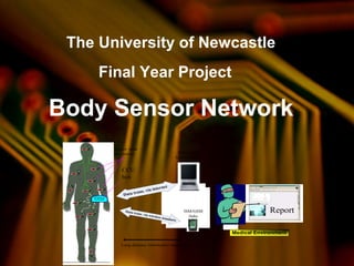
- 1. The University of Newcastle Final Year Project Body Sensor Network Sensor node electronics CCU CCU box Report Data trans. via internet Data trans. via wireless standarts Medical Environment Long distance information transmission ISM/GSM links Web-based Internet trans.
- 2. Acknowledgement • NEWCASTLE SUPERVISOR: DR. MEHMET R. YUCE • PSB SUPERVISOR: MR LEE CHIN KANG We would like to take this opportunity to express our gratitude to many individuals who have given us a lot of support for this project.
- 3. Agenda • Project Objectives • Project Outcome • Development of Temperature Sensor Node • Development of Pulse Rate Sensor Node • Development of Central Control Unit (CCU) • Loop Antenna Design and Results • Firmware Design • Software Design • Conclusion • Future Development
- 4. Project Objectives • To research, design and develop a BSN that comprises of several sensor nodes to monitor the vital signs of human and transmit wirelessly to the CCU for data display and storage. – Wireless Transmission of data via the MICS band for a range of 1~2 meters. – Battery operated, power efficient and light-weight. – Sensor nodes to extract accurate information from human body. – User Graphic Interface (GUI) to create database, display and store results.
- 5. Project Outcomes • Hardware Temperature Sensor Node, Pulse Rate Sensor Node and CCU are designed and fabricated on Printed Circuit Boards (PCB). Wireless Transmission of data via 402MHz (MICS band) with a range of 1~2 m with low power transmission mode. Battery operated using 2 coin batteries and maximum operating hours for worst case mode is 4.5 hours. Light-weight BSN with maximum 40 grams including
- 6. Project Outcomes • Software GUI successfully created and able to display real- time data and store data in a database. Firmware completed for Temperature Sensor Node, Pulse Rate Sensor Node and CCU • Technical Paper A paper was prepared for submission for ICC 2007, Smart Technologies for Tomorrow under Wireless Ad Hoc and Sensor Network.
- 7. Development of Temperature Sensor Node • Building Block of Temperature Sensor Node Temp Sensor ADC PIC16F877 Microcontroller 3 to 5 V Level shifter AMIS Transceiver
- 8. Development of Temperature Sensor Node • Temperature Sensor (Prototype 1) • Temperature Sensor (Final)
- 9. PCB Design of Sensor Nodes MCU and Level Shifter Power Management Antenna Transceiver and matching cct. Connector to Sensor
- 11. Battery Lifespan Calculation (Live-Monitoring Mode) • 5V Device ~ PIC16F877 (MCU) 15mA ~ SN74LVC4245A (Level Shifter) 1.5mA ~ LM35DZ (Temperature Sensor) 60uA Total: 17mA • 3.3V Device ~ AMIS-52100 (Transceiver) 25mA ~ SN74LVC4245A (Level Shifter) 1.5mA Total: 26.5mA Total maximum current consumption of Temperature Sensor Node: 43.5mA Battery rating: 560mAH Therefore, the battery can last, 560/43.5 = 12.9 hours for Live-Monitoring Mode
- 12. Development of Pulse Rate Sensor Node • Building Block of Pulse Rate Sensor Pulse Rate Sensor LNA Filter ADC PIC16F877 Microcontroller 3 to 5 V Level shifter AMIS Transceiver
- 13. Development of Pulse Rate Sensor Node • Pulse Rate Sensor (Prototype 1) • Pulse Rate Sensor (Final)
- 14. Development of Pulse Rate Sensor Node • Pulses captured at the pulse detector stage.
- 15. Development of Pulse Rate Sensor Node • Op-Amp stage (Simulation) • Op-Amp stage (Actual)
- 16. Pulse Rate Sensor Node
- 17. Battery Lifespan Calculation (Live-Monitoring Mode) • 5V Device ~ PIC16F877 (MCU) 15mA ~ SN74LVC4245A (Level Shifter) 1.5mA ~ LM358 (Op-amp) 1.2mA ~ SFH487 (Infrared Emitter) 80mA ~ SFH309FA (Phototransistor) 1.5mA Total: 99.2mA • 3.3V Device ~ AMIS-52100 (Transceiver) 25mA ~ SN74LVC4245A (Level Shifter) 1.5mA Total: 26.5mA Total maximum current consumption of Pulse Rate Sensor Node: 126mA Battery rating: 560mAH Therefore, the battery can last, 560/126 = 4.44 hours for Live-Monitoring Mode
- 18. Development of CCU • Building Block of CCU AMIS Transceiver PIC16F877 Microcontroller 3 to 5 V Level shifter Rs232 Level shifter
- 19. PCB Design for CCU Antenna Power Management MCU and Level Shifter RS232 Cct
- 20. CCU
- 21. Battery Lifespan Calculation (Live-Monitoring Mode) • 5V Device ~ PIC16F877 (MCU) 15mA ~ SN74LVC4245A (Level Shifter) 1.5mA ~ DG9415DQ (Selector) 2uA ~ MAX232AESE 10mA Total: 27mA • 3.3V Device ~ AMIS-52100 (Transceiver) 10mA ~ SN74LVC4245A (Level Shifter) 1.5mA Total: 11.5mA Total maximum current consumption of CCU: 38.5mA Battery rating: 560mAH Therefore, the battery can last, 560/38.5 = 14.55 hours for Live-Monitoring Mode
- 22. BSN Total Costing • Temperature Sensor Node: USD57.05 • Pulse Rate Sensor Node: USD58.95 • CCU: USD61.19 • Accessories: USD10 Total: USD187.19
- 23. Loop Antenna Design and Results • Loop Antenna design was reference from AN868 from Microchip, Designing Loop Antenna. • Some formulas used were entered into an excel sheet for easy calculation.
- 24. Loop Antenna Design and Results • Sensor Node Loop Antenna Design C28 tunes the input impedance of the Loop Antenna while C29 and C30 tunes the resonant frequency of the Loop Antenna.
- 25. Loop Antenna Design and Results • Sensor Antenna S11
- 26. Loop Antenna Design and Results • CCU Loop Antenna Design
- 27. Loop Antenna Design and Results • CCU Antenna S11
- 28. Loop Antenna Design and Results • Gain Measurement of Loop Antenna was reference to Free Space Path Loss Formulae. Pr = Received Power (dBm) Pt = Transmit Power (dBm) Gt = Transmitter Gain (dB) Gr = Receiver Gain (dB) λ = wavelength (m) R = Range (m) Π = 3.142
- 29. Loop Antenna Design and Results CCU Antenna Gain Measurement
- 30. Loop Antenna Design and Results Sensor Antenna Gain Measurement
- 31. Transmit Power Vs Range Transmit Power Vs Range 0 2 4 6 8 10 12 -24.000 -23.000 -22.000 -21.000 -20.000 -19.000 -18.000 -17.000 -16.000 Transmit Power (dBm) Range(m)
- 32. Data Format • Different types of data are using for Sensor nodes, CCU and GUI • To provide more reliable and error free wireless system Data Conversion Conversion Methods 8 bit integer to character fputc( ) Character to Float float_variable = (((float)char_variable)); String to double (for Visual C++) Double::TryParse(string, double_variable) Double to Integer (nearest estimation) integer_variable=double_variable 8 bit Integer Character Float String Double Integer 8 bit Integer 8 bit Integer Data Addres s Sensor Node CCU CCU PC PC PC 8 bit Integer Purpose To Store ADC value To receive 8 bit data To Calculate Temperature To Calculate Temperature To Display In text box To Store Data To Display Graph Firmware Design
- 33. C Program Script file CCS C compiler MPLAB IDE V7.31 ICD2 Programmer Firmware Design, Development and Implementation • High-level C programming Language is used • CCS C compiler is used for compiling • MPLAB IDE V7.31 is used as emulator • ICD2 Programmer is used for program downloading
- 34. Central Control Unit (CCU) Firmware Architecture • Communication with PC using RS232 • Communication with AMIC transceiver using I2C • Data Multiplexing between PC and Sensor nodes using selector IC • Error free Address and Data Polling from sensor nodes • Calculation for Actual Temperature using conversion factor • Timing controlling during data and address polling for different sensors Selector IC AMIS5210 RX/TX 74LVC4245 3V/0V PIC16F87 7 MAX232 5V/ 0V RX/TX -8V/+8V RX/TX 5V/ 0V
- 35. • Two way serial link and one way wireless link • RS232 is communication media for serial link • RF media is for wireless link Baud Rate 9600 Number of bits 8 SPRG Value (Decimal) 31 SPRGH Value 0 Fosc 20 MHz Percent Error (%) 1.73 Parity N Transmit PIN ( PIC16F877) C6 Receive PIN ( PIC16F877) C7 Operating Frequency 403.5 MHz TX output power +12dbm RX sensitivity -117dbm (min) Data rate 1 to 8 Kbps Fosc 20 MHz Modulation ASK/OOK Crystal Start time 15 us PLL lock time <50us Data Filter Up to 20 kHz RS 232 Serial link RF link Communication Scheme
- 36. Communication Protocol Architecture PC CCU Temperature Sensor node Pulse Rate Sensor node Send a Character Send Address Send Data Send Address Send Data Send Address Send Address Send Data Send Data Send Data Send Data
- 37. CCU Temperature Sensor node Pulse Rate Sensor node 1 or 2 or 3 or 4 Start Start Start Rcv num 1 or 2 or 3 or 4 Idle 1 or 2 Chk num Send Add Send Data Rcv Add Rcv Data Valid Add 3 or 4 Rcv Add Rcv Data Valid Add Send Data PC Start Chk button Send num Rcv Data Send Data Idle Send Data Send Add State Diagram and Logic Connection
- 38. Time Temperature Sensor Add Data Pulse Rate Sensor Add Data Add Data 1000 200 300 400 500 Time (ms) Add Data Add Data RF Link Package Format • 8 bits of address followed by data is transmitted • Different addresses (ID) are used for sensor nodes
- 39. Firmware interface for Sensor Node (ADC Portion) • PIC microcontroller built in ADC module is used • Temperature sensor is operating in 8 bits mode • Pulse rate sensor is operating in 10 bits mode • A/D clock 625 kHz is used by setting divisor to 32 • A/D Resolution for Temperature Sensor • A/D Resolution for Pulse rate Sensor 11
- 40. Calculation for Actual Temperature using conversion factor • Temperature calculation is done at Central Control Unit • LM35DZ is giving an output of 10 mV per Degree Centigrade • 8 bit ADC Is using and 10mV is corresponds to 1°C • Temperature calculation and data conversion to float in C program
- 41. Software Design Software Architecture and Implementation • Data entry for patient particulars • Graphical User Interface interaction • Data acquisition from sensor nodes • Data storage for partient particular, diagnosis and medical information • Real time data display Application Software • Microsoft Visual C++ 2005 Express edition • Installer 1.0.5 • Microsoft Platform SDK (Visual C++ 2005 Express edition) • Microsoft .net frame work Required Platforms
- 42. Graphical User Interface Interaction
- 43. Data entry for patient particulars Data Acquisition • Initiated by GUI ( presssing Get Display button) • Event handler program execute • Initialized serial communication (RS232 link)
- 44. Data Storage • Doctor incharge Patient’s particular, Diagnosis and Medical information can be stored • All data are stored in text file (small in size) • Auto file naming system ********************************************** ** THE UNIVERSITY OF NEWCASTLE ** ** Final Year Project ** ** Body Sensor Network ** ** Remote Health Monitoring System ** ********************************************** Date & Time: 08/12/2006 4:00:09 AM ---------------------------------------------- Patient's Particular ---------------------------------------------- Patient Name: Myo Naung Lwin ID/Passport Number: S7779190F Age: 29 Sex: Male Height: 1.8m Weight: 70kg Diagnosis: Project Headache!! ---------------------------------------------- Patient's Medical Information ---------------------------------------------- Body Temperature: 35.36 Body Temperature: 35.36 Body Temperature: 35.36 Body Temperature: 35.36 Body Temperature: 35.36 Body Temperature: 35.36 Body Temperature: 35.36 Body Temperature: 35.36 Body Temperature: 35.36 Body Temperature: 35.36 Pulse Rate:66 Pulse Rate:66 Pulse Rate:66 Pulse Rate:66 Pulse Rate:66 Pulse Rate:66 Pulse Rate:66 Pulse Rate:66 Pulse Rate:66 Pulse Rate:66 patient’ s name and date of data saving) • Real time temperature can be stored • Real time pulse rate can be stored • Data storage is done at PC ( file name is generated according to
- 45. Data Display • Professional quality graph display • Scaling has been done to suit for human body temperature and pulse rate
- 46. Conclusion There has been increased interest in wireless recording and monitoring real-time physiologic parameters (e.g. ECG, EEG, EOG, EMG, Neural, Blood Flow, Blood Pressure etc.) from a patient body in medical environments among researchers in the last decades medical environments among researchers in the last decades. With the advanced wireless technology, the healthcare can now be wireless. This project gives us a great experience in this up-coming trend and put us in an advantage of becoming the frontier in this new technology. Unlimited experiences were gain throughout the project development. New skills such as PIC programming, loop antenna design, multi- layer PCB design, Visual C++ and many more were picked up during the project.
- 47. Conclusion We learned that Project Management is a key element to determine the success of a project. With the experience gain in this project, we are confident that we can overcome any work-related problems in the future and solve them systematically.
- 48. Future Development There are other Human Vitals Signs such as Blood Pressure, Oxygen saturation, etc to be explored and research to incorporate into the Body Sensor Network Project. The 2nd RF link from CCU to Nurse Station or Data collection center can be implemented into the BSN. The Sensor nodes and CCU PCB size can be reduced further to make the product more commercialized. The current microcontroller size is too big. Consider a small size MCU and the overall size of both the Sensor Nodes and CCU will reduce greatly. Change the microcontroller to a 3V microcontroller. This will save up a level shifter IC and a 5V regulator. Make the entire circuit run in 3V and therefore a single 3V power will be sufficient. Design the Sensor Nodes to send data at intervals so as to save on power consumption of the battery.