

Recommended
More Related Content
What's hot
What's hot (20)
Viewers also liked
Viewers also liked (20)
Similar to Solar Lighting in Ecotect
Similar to Solar Lighting in Ecotect (20)
More from NYCCTfab
More from NYCCTfab (20)
Recently uploaded
Recently uploaded (20)
Solar Lighting in Ecotect
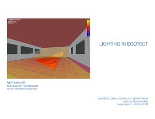
- 1. New York City College of Technology The City University of New York Lighting in Ecotect Architectural technology department written by Nicole Seekely revised April 15, 2010 8:25 PM
- 2. Notes: page 2 of 22 Lighting in Ecotect Step One: Once your model has been brought into Ecotect, click on the Visualize tab located on the very left side of the screen. This will show your model shaded based on materials you have assigned. The following are some useful shortcuts: Right Mouse Rotate Ctrl + Right Mouse Pan Shift + Right Mouse Zoom F2 Repeat Last F3 or Double Click Nodes On/Off F4 Isolate Selected Zone F5 Plan F6 Side F7 Front F8 Axonometric X,Y,or Z Nudge Object in Direction Shift + X,Y, or Z Nudge Object in Negative Direction Insert Insert Child Object (Door, Window, Void) Ctrl Hold to Move Cursor in Z direction instead of X,Y N Snaps On/Off A,C,G,I,L,M,O,P Snap Option (Align, Centre, Grid, Intersections, Lines, Midpoints, Orthogonal, Points) Ctrl + F Fit Grid to Model Spacebar Toggle among selected objects
- 3. Notes: If your location is not listed, there are ways of downloading additional weather files off the internet or creating your own. There is ta tutorial located at S:ARCH-2450 Trudell that takes you through the process of creating your own weather file. page 3 of 22 Lighting in Ecotect Step Two: To get the correct lighting analysis, you will need to load the weather data for your location. Click on the Earth symbol, and select Load Weather File. Select the appropriate location and hit Open.
- 4. Notes: page 4 of 22 Lighting in Ecotect Step Three: Hit F10 or Go to Display - Shadows to allow the current shadows for the time and day to show. You can set the time and day at the top of the screen next to where you set the weather data. You can also change the shading effects of your sur- faces by clicking on the Visualization Settings tab to the right. If you scroll down the screen, you can adjust settings such as Shade Sur- faces.
- 5. Notes: page 5 of 22 Lighting in Ecotect Step Four: Also in the Shadow Settings menu you can turn on/off the daily and annual sun paths. This will allow you to get and idea about the orientation of your building relative to the sun angle.
- 6. Notes: page 6 of 22 Lighting in Ecotect Step Five: Also in the Shadow Settings menu you can turn on the shadow range. This will show the shadows for the given day during the hours you set.
- 7. Notes: page 7 of 22 Lighting in Ecotect Incident Solar Radiation: You can run solar analysis on your building to see how much incident solar radia- tion hits each surface. There are several different settings you can use to show different information. Try starting with these and then experiment with others: Go to Calculate - Solar Ac- cess Analysis Leave all the default options selected as you go through the Wizard. Click OK in the end and allow time for the program to calcu- late. The status is shown on the bottom of the screen.
- 8. Notes: Make sure your normals are facing the correct way. The normal for each surface should be facing outwards. To check this, go to Display - Surface Normals. If the normal arrow is not in the correct direction, hit Ctrl+R to reverse its direction. page 8 of 22 Lighting in Ecotect You should end up with all the surfaces of your model col- ored according to the amount of incident solar radiation they receive at the given time. You can change the day and time, and the model will automati- cally update. You can change display set- tings and show more infor- mation by going to Display - Object Attribute Values.
- 9. Notes: page 9 of 22 Lighting in Ecotect How To Show Light Levels Across A Surface: Step One: Select the surface(s) you want to run the analysis on. Click on Modify - Surface Subdivi- sion - Rectangular Tiles Step Two: Select your subdivision size. The smaller the size, the more detailed and accurate your results will be but also the l onger the run time will be. You can adjust some settings to better fit your surface.
- 10. Notes: With the many subdivisions, don’t be surprised if the calculation takes several min- utes. page 10 of 22 Lighting in Ecotect Step Three: With the subdivided surface selected, go to Calculate - Solar Access Analysis. Step Four: Go through all the steps as before. Incident Solar Ra- diation, choose your Time Period, Average or Cumula- tive, Check that the values are calculated for selected objects only and clear values from other objects. For shad- ing mask, choose Detailed so that you can adjust the set- tings. For faster calculations, choose Medium and Low.
- 11. Notes: You can also show Text Values and change other settings from the Object Attribute Values menu. page 11 of 22 Lighting in Ecotect Step Five: You should end up with an array of colors depicting the level of radiation. You may need to adjust the scale if your surface is one color. Go to Display - Object Attribute Values - Custom Scale. Step Six: Change the value range until you get the desired effect.
- 12. Notes: Make sure your normals are facing the correct way. The normal for each surface should be facing outwards. To check this, go to Display - Surface Normals. If the normal arrow is not in the correct direction, hit Ctrl+R to reverse its direction. You’ll know you’ve done it right if your graph looks like this. If it is all gray (meaning completely in the shade all day), it’s likely your normals are reversed. page 12 of 22 Lighting in Ecotect You can also get more de- tailed information about a given surface. Click on the surface (you can select ob- jects in the 3D Editor tab, not the Visualize tab). Then go to the Analysis tab. Here you have 4 different options for Solar Exposure Calculations. Single Day - shows the amount of hourly exposure on the selected surface Average Daily - amount of radiation on surface on an average day each month Total Monthly - cumulative values for each month Full Hourly - same as total monthly, which each day’s results shown Hit Calculate after making a selection.
- 13. Notes: page 13 of 22 Lighting in Ecotect Internal Lighting Calcs It is possible to show the inte- rior lighting conditions as well. To do this, you’ll need to set up an Analysis Grid. Step one: Click on the Analysis Grid Tab to the right. The click on the Grid Management button. Usually the default settings are okay to start with. Note that here you can change the number of cells to get more precise information, but it will take much longer to calculate. Step two: The Z height of the grid should be set to something around 600mm or 2’. You can change this to however high or low you want it to be, but the default is the standard height for interior lighting cal- culations.
- 14. Notes: You will notice that the analysis grid doesn’t stretch over the whole floor. There is a perimeter gap. This is correct - you don’t want the grid to touch the walls or it will produce false information. page 14 of 22 Lighting in Ecotect Step Three: Select the floor and then hit the button “Auto-Fit Grid to Objects.” A menu will pop- up. You want to fit “Within” the “Selected Objects.” All the defaults should be okay to use.
- 15. Notes: page 15 of 22 Lighting in Ecotect Step Four: Go to Calculate - Lighting Analysis Step Five: Select “Natural Light Levels” and click Next. Keep it on the Analysis Grid and click Next. Adjust your ray-tracing to how precise you want it and click Next. The higher, the longer the calculation time. Enter your design sky illuminance or allow Ecotect to calculate it for you and click Next. Set your Window Cleanliness and click Next. Select Regula- tory Compliance or Accuracy Mode and click Next. Finally, click OK if everything looks good.
- 16. Notes: page 16 of 22 Lighting in Ecotect Step Six: You can adjust the display of the analysis grid in the Grid Settings menu. You can turn on/off grid lines, contour lines, etc. You can also show val- ues in 3D. You can also change the Con- tours setting. Try changing to .5 and you will get a much more gradiated effect.
- 17. Notes: page 17 of 22 Lighting in Ecotect Analysis in Radiance: You can bring your Ecotect model and information into another program called Radiance. This will allow for further Lighting Design Calcu- lations. Step One: You will need to set up a cam- era that will be the view from which information is shown in Radiance. Click the Camera button and choose to place Interactively. Step Two: Place the camera wherever you want an interior shot. Use Ctrl to move the cursor up in the Z direction. Click a second time for the direction of the camera.
- 18. Notes: To view through your camera, go to the Visualize tab and click on the Camera tab at the bottom of the screen. page 18 of 22 Lighting in Ecotect Step Three: With your analysis grid shown, you are ready to ex- port. Go to the export tab on the rightside menu. Click on Export Model Data. Step Four: Select ILLUMINANCE to ren- der the amount falling on the surfaces. Click Next. Choose Final Render and click Next. Choose your sky and click Next. Choose date and time and click Next. Gener- ate Interior views and select your image size, click Next. Make sure that you have your camera selected in the menu. Use Medium for your accura- cies. And finally, select your save location. Click OK. You may be prompted to locate the .exe file. This is usually at C:RadianceBin rad.exe
- 19. Notes: Navigate through the different images created by the tabs at the top. page 19 of 22 Lighting in Ecotect Step Five: Depending on how your set- tings are, it may take awhile for Radiance to render out the image. You can see the progress in the DOS prompt window. Eventually a window like this one should pop up. You can then generate a series of images with informa- tion overlayed: Make sure you’re on the first/ original image tab. Then select one of the options from the Information Overlay menu. Set your scale to be a maximum of 4000 instead of the default 1000. You can change the number of divisions as well, but 10 is a good start. Then click the green arrow to generate a new image.
- 20. Notes: page 20 of 22 Lighting in Ecotect Step Six: You can click on the image itself to generate the Lux for that particular point on the surface. This allows for a fairly precise analysis. You can save your images through the File menu.
- 21. Notes: To get the grid to show a gradient as seen, turn on your contours and off your grid- lines in the Analysis Grid Settings Tab. page 21 of 22 Lighting in Ecotect You can also import data such as Illuminance from Ra- diance back into Ecotect as shown in this model. Just make sure you select the Surface and/or Point Analysis option in the Wizard. This will automatically import the results back into the Ecotect analysis grid once Radiance is done.
- 22. Notes: page 22 of 22 Lighting in Ecotect Ecotect and Radiance use Lux as the default unit. To change the values to Foot- candles go to Grid Manage- ment, Edit Grid Data tab and type in V*0.093. This is because every 1 Lux is about 10 Footcandles.