Natgraph Table Top Exposure Systems & (Cd) Drying Cabinets
Natgraph Air Force Dryers & Options
1. EQUIPMENT SOLUTIONS
Air Force Dryers
stencil processing
screen printing
air force
ultra violet
infra red
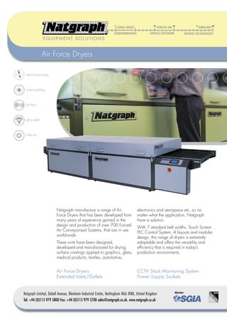
Natgraph manufacture a range of Air electronics and aerospace etc, so no
Force Dryers that has been developed from matter what the application, Natgraph
many years of experience gained in the have a solution.
design and production of over 700 Forced
With 7 standard belt widths, Touch Screen
Air Conveyorised Systems, that are in use
PLC Control System, 4 layouts and modular
world-wide.
design, this range of dryers is extremely
These units have been designed, adaptable and offers the versatility and
developed and manufactured for drying efficiency that is required in today’s
surface coatings applied to graphics, glass, production environments.
medical products, textiles, automotive,
Air Force Dryers CCTV Stack Monitoring System
Extended Inlets/Outlets Power Supply Sockets
Natgraph Limited, Dabell Avenue, Blenheim Industrial Estate, Nottingham NG6 8WA, United Kingdom
Tel: +44 (0)115 979 5800 Fax: +44 (0)115 979 5700 sales@natgraph.co.uk. www.natgraph.co.uk
2. Air Force Dryers
The Natgraph modular range of Air Force Dryers down, forced air on/off, heated air temperature
is available in 7 belt widths from 90cm through control via feedback loop (0.1°C resolution) and
to 215cm, therefore an Air Force Dryer can be forced cold air on/off. A dryer fault diagnosis
specified for all drying requirements. These can system is included with audible warning of fault
be from small print runs on Hand Printing Tables conditions, including air pressures, over temperature
or medium length production runs printed on sensors and belt speeds.
semi-automatic screenprinting machines, through to 4 emergency stops complete a comprehensive
continuous high speed production on fully automatic control facility.
cylinder presses.
A 2 metre long, high pressure warm air module has
motor/vee belt driven fan assemblies, connected
to rigid galvanised steel internal ducting. Air is
forced at high pressure through fast response
heating elements up into the hood and then through
a specific pattern of nozzles, in removable metal
jet plates down onto the substrate. The maximum
temperature of a standard Air Force Dryer is 85°C,
although special high temperature versions are
available. The hinged hoods are double skinned,
fully insulated and fitted with large handles, access
to the belt is aided by 2 support legs which raise
with the hood, from inside the module’s base
section.
A 2 metre long, high pressure cooler similar in
4 Heating and 2 Cooling modules construction to the warm air module. Air input to this
module is through a large inlet duct, which should
be connected to free air for optimum efficiency.
The vital element in accelerated drying of solvent A proportion of the cooling air is recirculated.
based inks is high velocity, high volume air An optional extracted cooler is available.
delivered efficiently to the complete substrate area.
Natgraph Air Force Dryers recirculate large volumes
of air (over 15,0003m/hour can be recirculated
in each module, for special applications). Drying
therefore takes place at lower temperatures resulting
in economical operation and good substrate
stability. Economy is maintained by a high level of
insulation and recirculating the majority of air. A
proportion of the solvent laden air is always
Touch Screen PLC bled away through a separate outlet duct for
Control Unit safety reasons.
A typical Natgraph Air Force Dryer will consist of A 0.5 metre exit section contains the belt drive motor,
the following specification of modules:- drive linkage tensioning device and drive roller.
A 1 metre long inlet section (which can be This section can also be supplied in other lengths if
extended), which has the main control box attached required.
and contains vacuum hold-down fans. In high Air Force Dryers can be specified to be anything
speed operation this is very useful, particularly from a minimum of 3.5m long, depending upon
with fully automatic presses. The belt is of an open the required production speed and the drying rate
mesh, P.T.F.E. coated fibre glass construction, with of the inks used. The final specification is best
reinforced edges and a protection flap below the determined by carrying out drying trials in the
Air Force Dryer and joint. All the dryer’s functions are operated through Natgraph Nottingham based ‘Drying Solutions
Automatic Sheet Stacker a large Touch Screen Panel (HMI), these include Centre’.
belt start/stop, belt speed (3 – 50m/minute, 0.1m
resolution, via feedback loop), inlet vacuum hold- These dryers require a three phase power supply.
EQUIPMENT SOLUTIONS 2 of 4
3. Air Force Dryers
Features
• Touch Screen, PLC Control System • Vacuum hold-down on inlet
• Motor/vee belt, fan assemblies • Modular construction
• Fully insulated • P.T.F.E. fibre glass belt
• Easy access hoods • Castors & jacking feet
• Extraction control • Colour coded to industry standards
Options
A variety of options are available for the range of Natgraph Air Force Dryers, these are intended to make
Extended Inlet the dryer more productive and versatile, whilst ensuring they fit into the intended location as efficiently and
economically as possible.
Extended inlets and outlets
The inlet and the outlet of these dryers can be extended to enable the dryer to operate with more than one
printing machine, or allow extra time for ‘ink flow’. These extensions are in multiples of 0.5, or 1m sections
and can be fitted with vacuum hold-down systems.
Power Supply Socket Outlets
Electrical power supply socket outlets can be fitted at each end of the dryers, these are intended to
provide an electrical supply for the printing machine and Stacker or Vibrating Collection Tray. This
Power Supply Sockets facility means that only one cable needs to be provided to supply the complete printing line, thus saving
on installation costs.
CCTV Stack Monitoring System
A colour CCTV system can be fitted to all Natgraph dryers, this system includes a freestanding, mast
mounted camera above the stacker and a dedicated TV monitor mounted on a fully adjustable stand
above the inlet of the dryer. This allows the operator to see the stacker without leaving the printing
machine, which is very important when operating long, high speed, fully automatic printing lines.
Layout & Paint Finish
Air Force Dryers can be manufactured in any layout to suit the intended location or printing machine with
controls and ducting on either side. This can result in significant space saving.
CCTV Stack
Natgraph also have the ability to finish these units in industry standard machine colours, so that the dryer
Monitoring System
will match existing print lines, or a customer’s house colours.
Natgraph Air Force Dryers are mostly manufactured in single, double or triple module
combinations, these are from 3.5m upwards in length and the final specification is
dependent upon the production speeds required and the drying rate of the ink.
The best way to determine the ideal specification is to carry out drying
trials in Natgraph’s Nottingham based ‘Drying Solution Centre’,
which is available to all.
Special Paint Finish
EQUIPMENT SOLUTIONS
3 of 4
4. Specifications
Air Force Dryers
The following specifications are common to all Air Force Dryers
Belt Height 79cm – 90cm (31”-37”) Adjustable by the feet, higher options available.
Belt Speed 3 – 50m per minute (10’ – 166’) Slower speeds are available to order.
Height 114cm – 129cm (45” – 51”) Adjustable by the dryer’s feet.
Module Length 2m (79”)
Voltage Three Phase 400 Volts 50/60 Hz. AC
These figures apply to individual model sizes.
Model No. 90 110 130 155 170 185 215
Belt/drying/curing width 90cm (36”) 110 (43”) 130cm (51”) 155cm (61”) 170cm (67”) 185cm (73”) 215cm (84”)
Module width 158cm (62”) 178cm (70”) 198cm (78”) 223cm (88”) 238cm (94”) 253cm (100”) 283cm (112”)
(Weights can be confirmed by Natgraph depending upon the size/type and number of modules used.)
Electrical
Module Type 2m, high pressure, warm (85°C maximum), air modules
Model No. 90 110 130 155 170 185 215
Heating Elements 18kW 18kW 18kW 24kW 24kW 24kW 24kW
Current (Max. Amps) 26 26 26 34 34 34 34
Motor(s) 2.2kW 3kW 3kW 4kW 4kW 6kW 8kW
Current (Max. Amps) 5 7 7 10 10 14 17
Module Type 2m, high pressure, cold (ambient), air modules,
Model No. 90 110 130 155 170 185 215
Motor(s) 2.2kW 3kW 3kW 4kW 4kW 6kW 8kW
Current (Max. Amps) 5 7 7 10 10 14 17
Module Type 2m, 2 lamp UV/cold (ambient), air modules, (UV lamp power 120watts/cm - 300 watts/inch)
Model No. 90 110 130 155 170 185 215
Lamp Power 25kW 31kW 36kW 43kW 47kW 51kW 59kW
Current (run) (Amps) 50 60 70 85 95 705 120
Motor(s) 2.2kW 3kW 4kW 4kW 4kW 6kW 8kW
Current (Max. Amps) 5 7 10 10 10 14 17
Air Figures are in 1,000m3/hour, per 2m module
Model No. 90 110 130 155 170 185 215
2m, high pressure, warm (85°C maximum), air modules
Recirculated Air 6.8 8.2 9.5 11.5 12.6 13.1 15.8
Exhaust Air (Adjustable) 1.9 2.1 2.3 2.6 2.5 2.6 2.9
2m, high pressure, cold (ambient), air modules.
Intake Air 4.3 5.6 6.7 7.7 8.4 8.9 10.3
2m 2 lamp UV/cold (ambient), air modules.
Intake Air 2.8 3.2 3.8 4 4.3 4.8 5.6
Exhaust Air 2.9 3.4 4 4.2 4.6 5 5.8
NOTE: When calculating power supply sizes for Air Force Dryers, add all the motor and heating element currents of the modules involved together to give the final figure. For Air
Forced/UV Combinations, add all the motor currents of the modules involved to the lamp current, but do not include the heating elements. This is because a safety interlock ensures
that the air heating elements and UV lamps cannot be used at the same time. The UV lamp currents are calculated with 2 lamps at full power.
Example: Model 110 Air Force Dryer, 2m warm, 2m cold = 26 + 7 + 7 = 40 Amps.,
Model 110 Air Force UV/Combination Dryer, 2m warm, 2m 2 lamp UV cold = 7 + 60 +7 = 74 Amps.
Typical power consumption of a Model 110 Air Forced Dryer, 2m warm, 2m cold, running at 50°C with an ambient temperature of 20°C is 10kW per hour (including all motors),
at average U.K. power costings, this represents a running cost of below 70p per hour.
Distributed by:
Download our brochures at www.natgraph.co.uk
4 of 4
06 The manufacturer’s policy is one of continuous improvement and the manufacturer therefore reserves the right to change or modify the design without prior notice. The technical specifications given are therefore for information only.