Contenu connexe Similaire à Ieee c57-15-1999 Similaire à Ieee c57-15-1999 (8) 1. Recognized as an IEEE Std C57.15-1999
American National Standard (ANSI) (Revision of
IEEE Std C57.15-1986)
IEEE Standard Requirements,
Terminology, and Test Code
for Step-Voltage Regulators
Sponsor
Transformers Committee
of the
IEEE Power Engineering Society
Approved 16 September 1999
IEEE-SA Standards Board
Abstract: Electrical, mechanical, and safety requirements of oil-filled, single- and three-phase
voltage regulators not exceeding regulation of 2500 kVA (for three-phase units) or 833 kVA (for
single-phase units) are covered.
Keywords: electrical, mechanical, safety, step-voltage regulators, test code
The Institute of Electrical and Electronics Engineers, Inc.
3 Park Avenue, New York, NY 10016-5997, USA
Copyright © 2000 by the Institute of Electrical and Electronics Engineers, Inc.
All rights reserved. Published 13 April 2000. Printed in the United States of America.
Print: ISBN 0-7381-1833-8 SH94799
PDF: ISBN 0-7381-1834-6 SS94799
No part of this publication may be reproduced in any form, in an electronic retrieval system or otherwise, without the prior
written permission of the publisher.
2. IEEE Standards documents are developed within the IEEE Societies and the Standards Coordinating Com-
mittees of the IEEE Standards Association (IEEE-SA) Standards Board. Members of the committees serve
voluntarily and without compensation. They are not necessarily members of the Institute. The standards
developed within IEEE represent a consensus of the broad expertise on the subject within the Institute as
well as those activities outside of IEEE that have expressed an interest in participating in the development of
the standard.
Use of an IEEE Standard is wholly voluntary. The existence of an IEEE Standard does not imply that there
are no other ways to produce, test, measure, purchase, market, or provide other goods and services related to
the scope of the IEEE Standard. Furthermore, the viewpoint expressed at the time a standard is approved and
issued is subject to change brought about through developments in the state of the art and comments
received from users of the standard. Every IEEE Standard is subjected to review at least every five years for
revision or reaffirmation. When a document is more than five years old and has not been reaffirmed, it is rea-
sonable to conclude that its contents, although still of some value, do not wholly reflect the present state of
the art. Users are cautioned to check to determine that they have the latest edition of any IEEE Standard.
Comments for revision of IEEE Standards are welcome from any interested party, regardless of membership
affiliation with IEEE. Suggestions for changes in documents should be in the form of a proposed change of
text, together with appropriate supporting comments.
Interpretations: Occasionally questions may arise regarding the meaning of portions of standards as they
relate to specific applications. When the need for interpretations is brought to the attention of IEEE, the
Institute will initiate action to prepare appropriate responses. Since IEEE Standards represent a consensus of
all concerned interests, it is important to ensure that any interpretation has also received the concurrence of a
balance of interests. For this reason, IEEE and the members of its societies and Standards Coordinating
Committees are not able to provide an instant response to interpretation requests except in those cases where
the matter has previously received formal consideration.
Comments on standards and requests for interpretations should be addressed to:
Secretary, IEEE-SA Standards Board
445 Hoes Lane
P.O. Box 1331
Piscataway, NJ 08855-1331
USA
Note: Attention is called to the possibility that implementation of this standard may
require use of subject matter covered by patent rights. By publication of this standard,
no position is taken with respect to the existence or validity of any patent rights in
connection therewith. The IEEE shall not be responsible for identifying patents for
which a license may be required by an IEEE standard or for conducting inquiries into
the legal validity or scope of those patents that are brought to its attention.
Authorization to photocopy portions of any individual standard for internal or personal use is granted by the
Institute of Electrical and Electronics Engineers, Inc., provided that the appropriate fee is paid to Copyright
Clearance Center. To arrange for payment of licensing fee, please contact Copyright Clearance Center, Cus-
tomer Service, 222 Rosewood Drive, Danvers, MA 01923 USA; (978) 750-8400. Permission to photocopy
portions of any individual standard for educational classroom use can also be obtained through the Copy-
right Clearance Center.
3. Introduction
(This introduction is not part of IEEE Std C57.15-1999, IEEE Standard Requirements, Terminology, and Test Code for
Step-Voltage Regulators.)
The working group has undertaken the task to update this standard to
a) Reflect the latest revisions of IEEE Std C57.12.00 and IEEE Std C57.12.90.
b) Permit the winding temperature rise to increase from 55 °C to 65 °C for selected regulator (sealed)
designs.
c) Adapt the new IEEE approved format to ensure compatibility with the latest ISO and IEC standards.
d) Eliminate references to induction voltage and dry-type regulators.
e) Revise the list of standard sizes.
The working group membership for the preparation of this standard was as follows:
Craig A. Colopy, Co-Chair
Tom Diamantis, Co-Chair
Sam Aguirre Robert Grunert Sam Michael
Glenn Andersen Ken Hanus Tom Pekarek
Wallace Binder James Harlow Jerry Rowe
Jerry H. Bishop Ron Jordan Ron Stahara
Kevin Edwards Mark Loveless Ralph D. Wakeam
The following members of the balloting committee voted on this standard:
Sam Aguirre Keith R. Highton Larry C. Pearson
David Aho Philip J. Hopkinson Linden W. Pierce
Glenn Andersen Bert R. Hughes Paul. Pillitteri
Donald E. Ballard Rowland I. James R. Leon Plaster
Ron L. Barker Gene Kallaur John R. Rossetti
Mike Barnes Egon Koenig Subhas Sarkar
A. Bartek Donald L. Lowe Vic Shenoy
Martin Baur William A. Maguire Hyeong Jin Sim
Edward A. Bertolini K. T. Massouda Kenneth R. Skinger
Wallace Binder John W. Matthews Leonard R. Smith
Jerry H. Bishop Nigel P. McQuin James E. Smith
Alain Bolliger Charles Patrick McShane James E. Smith
Alvaro Cancino Joe Melanson Steven L. Snyder
Craig A. Colopy Sam Michael Craig L. Stiegemeier
Jerry L. Corkran C. Kent Miller Ron W. Stoner
Tom Diamantis R. E. Minkwitz Sr. Richard E. Sullivan
Dieter Dohnal Daniel H. Mulkey James A. Thompson
Carlos Gaytan Paul E. Orehek Thomas P. Traub
Harry D. Gianakouros Gerald A. Paiva Subhash C. Tuli
Robert Grunert B. K. Patel Joseph J. Vaschak
N. Wayne Hansen Sanjay Y. Patel Robert A. Veitch
James Harlow Wesley F. Patterson Barry H. Ward
Theodore J. Haupert Paulette A. Payne Christopher Wickersham
William R. Henning B. Scott Wilson
Copyright © 2000 IEEE. All rights reserved. iii
4. When the IEEE-SA Standards Board approved this standard on 16 September 1999, it had the following
membership:
Richard J. Holleman, Chair
Donald N. Heirman, Vice Chair
Judith Gorman, Secretary
Satish K. Aggarwal James H. Gurney Louis-François Pau
Dennis Bodson Lowell G. Johnson Ronald C. Petersen
Mark D. Bowman Robert J. Kennelly Gerald H. Peterson
James T. Carlo E. G. “Al” Kiener John B. Posey
Gary R. Engmann Joseph L. Koepfinger* Gary S. Robinson
Harold E. Epstein L. Bruce McClung Akio Tojo
Jay Forster* Daleep C. Mohla Hans E. Weinrich
Ruben D. Garzon Robert F. Munzner Donald W. Zipse
*Member Emeritus
Also included is the following nonvoting IEEE-SA Standards Board liaison:
Robert E. Hebner
Greg Kohn
IEEE Standards Project Editor
iv Copyright © 2000 IEEE. All rights reserved.
5. Contents
1. Overview.............................................................................................................................................. 1
1.1 Scope............................................................................................................................................ 1
1.2 Purpose......................................................................................................................................... 1
1.3 Word usage .................................................................................................................................. 1
2. References............................................................................................................................................ 1
3. Definitions............................................................................................................................................ 2
4. Service conditions................................................................................................................................ 7
4.1 Usual service conditions .............................................................................................................. 7
4.2 Loading at other than rated conditions......................................................................................... 7
4.3 Unusual service conditions .......................................................................................................... 8
4.4 Frequency..................................................................................................................................... 9
5. Rating data ......................................................................................................................................... 10
5.1 Cooling classes of regulators ..................................................................................................... 10
5.2 Ratings in kVA .......................................................................................................................... 10
5.3 Operating voltage limits............................................................................................................. 11
5.4 Supplementary continuous-current ratings ................................................................................ 11
5.5 Voltage supply ratios ................................................................................................................. 11
5.6 Insulation levels ......................................................................................................................... 14
5.7 Losses......................................................................................................................................... 14
5.8 Short-circuit requirements ......................................................................................................... 17
5.9 Tests ........................................................................................................................................... 18
6. Construction....................................................................................................................................... 19
6.1 Bushings..................................................................................................................................... 19
6.2 Terminal markings ..................................................................................................................... 19
6.3 Diagram of connections ............................................................................................................. 21
6.4 Nameplates................................................................................................................................. 21
6.5 Tank construction....................................................................................................................... 22
6.6 Tank grounding provisions ........................................................................................................ 22
6.7 Components and accessories...................................................................................................... 22
7. Other requirements............................................................................................................................. 23
7.1 Other supplementary continuous-current ratings....................................................................... 23
7.2 Other short-circuit capability ..................................................................................................... 24
7.3 Other components and accessories ............................................................................................ 24
8. Test code ............................................................................................................................................ 25
8.1 Resistance measurements........................................................................................................... 25
8.2 Polarity test ................................................................................................................................ 28
8.3 Ratio tests................................................................................................................................... 29
8.4 No-load losses and excitation current ........................................................................................ 31
Copyright © 2000 IEEE. All rights reserved. v
6. 8.5 Impedance and load losses......................................................................................................... 36
8.6 Dielectric tests............................................................................................................................ 41
8.7 Temperature rise ........................................................................................................................ 52
8.8 Short-circuit tests ....................................................................................................................... 58
8.9 Data ............................................................................................................................................ 62
9. Control systems.................................................................................................................................. 65
9.1 General....................................................................................................................................... 65
9.2 Control device construction ....................................................................................................... 65
9.3 Control system requirements ..................................................................................................... 66
9.4 Tests ........................................................................................................................................... 68
Annex A (informative) Unusual temperature and altitude conditions........................................................... 71
Annex B (informative) Bushing and field dielectric tests ............................................................................. 73
Annex C (informative) Bibliography............................................................................................................. 74
Copyright © 2000 IEEE. All rights reserved. vi
7. IEEE Standard Requirements,
Terminology, and Test Code for
Step-Voltage Regulators
1. Overview
1.1 Scope
This standard describes electrical, mechanical, and safety requirements of oil-filled, single- and three-phase
step-voltage regulators not exceeding a regulation of 2500 kVA (for three-phase units) or 833 kVA (for
single-phase units). This standard does not apply to load tap-changing transformers.
1.2 Purpose
This standard is intended as a basis for the establishment of performance, limited electrical and mechanical
interchangeability, and safety requirements of equipment described. It also assists in the proper selection of
such equipment.
1.3 Word usage
When this document is used on a mandatory basis, the word shall indicates mandatory requirements; and the
words should or may refer to matters that are recommended or permissive, but not mandatory.
2. References
This standard shall be used in conjunction with the following publications. When the following standards are
superseded by an approved revision, the revision shall apply.
ANSI C57.12.20-1997, American National Standard for Transformers—Standard for Overhead Type
Distribution Transformers, 500 kVA and Smaller: High Voltage, 34 500 Volts and Below; Low Voltage,
7970/13 800 Y Volts and Below.1
1ANSI C57.12.20-1997 is available from the Institute of Electrical and Electronics Engineers, 445 Hoes Lane, P.O. Box 1331, Piscat-
away, NJ 08855-1331, USA (http://standards.ieee.org/).
Copyright © 2000 IEEE. All rights reserved. 1
8. IEEE
Std C57.15-1999 IEEE STANDARD REQUIREMENTS, TERMINOLOGY, AND
ANSI C84.1-1995, American National Standard Voltage Ratings (60 Hz) for Electric Power Systems and
Equipment.2
IEEE Std 4-1995, IEEE Standard Techniques for High-Voltage Testing.3
IEEE Std 315-1975 (Reaff 1993), IEEE Standard Graphic Symbols for Electrical and Electronics Diagrams
(Including Reference Designation Letters).
IEEE Std C37.90.1-1989 (Reaff 1994), IEEE Standard Surge Withstand Capability (SWC) Tests for
Protective Relays and Relay Systems.
IEEE Std C57.12.00-1993, IEEE Standard General Requirements for Liquid-Immersed Distribution, Power,
and Regulating Transformers.
IEEE Std C57.12.80-1978 (Reaff 1992), IEEE Standard Terminology for Power and Distribution
Transformers.
IEEE Std C57.12.90-1999, IEEE Standard Test Code for Liquid-Immersed Distribution, Power, and
Regulating Transformers.
IEEE Std C57.13-1993, IEEE Standard Requirements for Instrument Transformers.
IEEE Std C57.19.00-1991 (Reaff 1997), IEEE Standard General Requirements and Test Procedure for
Outdoor Power Apparatus Bushings.
IEEE Std C57.95-1984 (Reaff 1991), IEEE Guide for Loading Liquid-Immersed, Step-Voltage and Induc-
tion-Voltage Regulators (withdrawn).4
IEEE Std C57.98-1993, IEEE Guide for Transformer Impulse Tests.
IEEE Std C57.106-1991, IEEE Guide for Acceptance and Maintenance of Insulating Oil in Equipment
(withdrawn).5
3. Definitions
For the purposes of this standard, the following terms and definitions apply. IEEE Std C57.12.80-19786 and
The IEEE Standards Dictionary of Electrical and Electronics Terms [B7]7 should be referenced for terms not
defined in this clause.
3.1 ambient temperature: The temperature of the medium, such as air or water, into which the heat
generated in the equipment is dissipated.
3.2 angular displacement of polyphase regulator: (A) The time angle, expressed in degrees, between the
line-to-neutral voltage of the reference identified source voltage terminal S1 and the line-to-neutral voltage
2ANSI publications are available from the Sales Department, American National Standards Institute, 11 West 42nd Street, 13th Floor,
New York, NY 10036, USA (http://www.ansi.org/).
3IEEE publications are available from the Institute of Electrical and Electronics Engineers, 445 Hoes Lane, P.O. Box 1331, Piscataway,
NJ 08855-1331, USA (http://standards.ieee.org/).
4IEEE Std C57.95-1984 has been withdrawn; however, copies can be obtained from Global Engineering, 15 Inverness Way East,
Englewood, CO 80112-5704, USA, tel. (303) 792-2181 (http://www.global.ihs.com/).
5IEEE Std C57.106-1991 has been withdrawn; however, copies can be obtained from Global Engineering.
6Information on references can be found in Clause 2.
7The numbers in brackets correspond to those of the bibliography in Annex C.
2 Copyright © 2000 IEEE. All rights reserved.
9. IEEE
TEST CODE FOR STEP-VOLTAGE REGULATORS Std C57.15-1999
of the corresponding identified load voltage terminal L1. (B) The connection and arrangement of terminal
markings for three-phase regulators in a wye connection has an angular displacement of zero degrees. (C)
The connection and arrangement of terminal markings for three-phase regulators in a delta connection has
an angular displacement of zero degrees when the regulator is on the neutral tap position. When the regulator
is on a tap position other than neutral, the angular displacement will be other than zero degrees. The angular
displacement with the regulator connected in delta will be less than ±5° for a ±10% range of regulation.
3.3 autotransformer: A transformer in which part of one winding is common to both the primary and the
secondary circuits associated with that winding.
3.4 common winding: That part of the autotransformer winding that is common to both the primary and
secondary circuits. Syn: shunt winding.
3.5 conservator system: An oil preservation system in which the oil in the main tank is sealed from the
atmosphere, over the temperature range specified, by means of an ancillary tank partly filled with oil and
connected to the completely filled main tank. Syn: expansion tank system.
3.6 dielectric tests: Tests that consist of the application of a voltage higher than the rated voltage for a
specified time for the purpose of determining the adequacy of insulating materials against breakdown, and
for spacing under normal conditions.
3.7 excitation current: The current that maintains the excitation of the regulator. It may be expressed in
amperes, per unit, or percent of the rated current of the regulator.
3.8 excitation losses: See: no-load losses.
3.9 expansion tank system: See: conservator system.
3.10 gas-oil sealed system: An oil preservation system in which the interior of the tank is sealed from the
atmosphere, over the temperature range specified, by means of an ancillary tank or tanks to form a gas-oil
seal operating on the manometer principle.
3.11 impedance voltage drop: The phasor sum of the resistance voltage drop and the reactance voltage
drop. For regulators, the resistance drop, the reactance drop, and the impedance drop are, respectively, the
sum of the primary and secondary drops reduced to the same terms. They are usually expressed in per unit or
percent of the rated voltage of the regulator. Since they differ at different operating positions of the regulator,
two values of impedance shall be considered, in practice, to be the tap positions that result in the minimum
and the maximum impedance. Neutral position has the minimum amount of impedance.
3.12 impedance voltage of a regulator: The voltage required to circulate rated current through one winding
of the regulator when another winding is short-circuited, with the respective windings connected as for a
rated voltage operation. Impedance voltage is usually referred to the series winding, and then that voltage is
expressed in per unit, or percent, of the rated voltage of the regulator.
3.13 indoor regulator: A regulator that, because of its construction, must be protected from the weather.
3.14 line-drop compensator: A device that causes the voltage regulating device to vary the output voltage
an amount that compensates for the impedance voltage drop in the circuit between the regulator and a prede-
termined location on the circuit (sometimes referred to as the load center).
3.15 liquid: Refers to both synthetic fluids and mineral transformer oil.
NOTE—Some synthetic fluids may be unsuitable for use in the arcing environment of a step-voltage regulator.
Copyright © 2000 IEEE. All rights reserved. 3
10. IEEE
Std C57.15-1999 IEEE STANDARD REQUIREMENTS, TERMINOLOGY, AND
3.16 liquid-immersed regulator: A regulator in which the core and coils are immersed in an insulating
liquid.
3.17 liquid-immersed self-cooled (Class ONAN): A regulator having its core and coil immersed in a liquid
and cooled by the natural circulation of air over the cooling surfaces.
3.18 liquid-immersed self-cooled/forced-air-cooled (Classes ONAN/ONAF and ONAN/ONAF/ONAF):
A regulator having its core and coils immersed in liquid and having a self-cooled rating with cooling
obtained by the natural circulation of air over the cooling surface and a forced-air-cooled rating with cooling
obtained by the forced circulation of air over this same cooling surface.
3.19 liquid-immersed self-cooled/forced-air-cooled/forced-liquid-cooled (Class ONAN/ONAF/OFAF):
A regulator having its core and coils immersed in liquid and having a self-cooled rating with cooling
obtained by the natural circulation of air over the cooling surface; a forced-air-cooled rating with cooling
obtained by the forced circulation of air over this same air cooling surface; and a forced-liquid-cooled rating
with cooling obtained by the forced circulation of liquid over the core and coils and adjacent to this same
cooling surface over which the cooling air is being forced-circulated.
3.20 liquid-immersed water-cooled (Class ONWF): A regulator having its core and coils immersed in a
liquid and cooled by the natural circulation of the liquid over the water-cooled surface.
3.21 liquid-immersed water-cooled/self-cooled (Class ONWF/ONAN): A regulator having its core and
coils immersed in liquid and having a water-cooled rating with cooling obtained by the natural circulation of
liquid over the water-cooled surface, and a self-cooled rating with cooling obtained by the natural circulation
of air over the air-cooled surface.
3.22 load losses of a regulator: Those losses that are incident to the carrying of the load. Load losses
include I2R loss in the windings due to load current, stray loss due to stray fluxes in the windings, core
clamps, and so forth.
3.23 no-load losses: Those losses that are incident to the excitation of the regulator. No-load losses include
core loss, dielectric loss, conductor loss in the winding due to exciting current, and conductor loss due to
circulating current in parallel windings. These losses change with the excitation voltage. Syn: excitation
losses.
3.24 nominal system voltage: A nominal value assigned to a system or circuit of a given voltage for the
purpose of convenient designation. The term nominal voltage designates the line-to-line voltage, as distin-
guished from the line-to-neutral voltage. It applies to all parts of the system or circuit.
3.25 nonsealed system: A system in which a tank or compartment is vented to the atmosphere usually with
two breather openings to permit circulation of air across the gas space above the oil. Circulation can be made
unidirectional when a pipe is extended up through the oil and is heated by the oil to induce movement of air
drawn from the outside into the gas space and across the oil to a breather on top of the tank.
3.26 outdoor regulator: A regulator designed for use outside of buildings.
3.27 polarity: (A) The polarity of a regulator is intrinsic in its design. Polarity is correct if the regulator
boosts the voltage in the “raise” range and bucks the voltage in the “lower” range. The relative polarity of the
shunt winding and the series windings of a step-voltage regulator will differ in the boost and buck modes
between Type A and Type B regulators. (B) The relative instantaneous polarity of the main transformer
windings, instrument transformer(s), and utility winding(s), as applicable, will be designated by an appropri-
ate polarity mark on the diagram of connection on the nameplate, in accordance with 6.3 of IEEE Std
C57.15-1999.
4 Copyright © 2000 IEEE. All rights reserved.
11. IEEE
TEST CODE FOR STEP-VOLTAGE REGULATORS Std C57.15-1999
3.28 pole-type regulator: A regulator that is designed for mounting on a pole or similar structure.
3.29 primary circuit: The circuit on the input side of the regulator.
3.30 rated range of regulation of a voltage regulator: The amount that the regulator will raise or lower its
rated voltage. The rated range may be expressed in per unit, or in percent, of rated voltage; or it may be
expressed in kilovolts.
3.31 rated voltage (of equipment): The voltage to which operating and performance characteristics are
referred.
3.32 rated voltage of a step-voltage regulator: The voltage for which the regulator is designed and on
which performance characteristics are based.
3.33 rated voltage of a winding: The rated voltage of a winding is the voltage to which operating and
performance characteristics are referred.
3.34 rated voltage of the series winding of a step-voltage regulator: The voltage between terminals of the
series winding, with rated voltage applied to the regulator, when the regulator is in the position that results in
maximum voltage change and is delivering rated output at 80% lagging power factor.
3.35 rating in kVA of a voltage regulator: (A) The rating that is the product of the rated load amperes and
the rated “raise” or “lower” range of regulation in kilovolts (kV). If the rated raise and lower range of regula-
tion are unequal, the larger shall be used in determining the rating in kVA. (B) The rating in kVA of a three-
phase voltage regulator is the product of the rated load amperes and the rated range of regulation in kilovolts
multiplied by 1.732.
3.36 reactance voltage drop: The component of the impedance voltage in quadrature with the current.
3.37 regulated circuit: The circuit on the output side of the regulator, where it is desired to control the volt-
age, or the phase relation, or both. The voltage may be held constant at any selected point on the regulated
circuit.
3.38 resistance method of temperature determination: The determination of the temperature by
comparison of the resistance of a winding at the temperature to be determined with the resistance at a known
temperature.
3.39 resistance voltage drop: The component of the impedance voltage in phase with the current.
3.40 sealed tank system: A method of oil preservation in which the interior of the tank is sealed from the
atmosphere and in which the gas volume plus the oil volume remains constant. The regulator shall remain
effectively sealed for top oil temperature range of –5 °C to 105 °C, continuous, and under the operating
conditions described in IEEE Std C57.95-1984.
3.41 series winding: That portion of the autotransformer winding that is not common to both the primary
and secondary circuits, but is connected in series between the input and output circuits.
3.42 shunt winding: See: common winding.
3.43 station-type regulator: A regulator designed for ground-type installations in stations or substations.
3.44 step-voltage regulator (transformer type): An induction device having one or more windings in shunt
with, and excited from, the primary circuit, and having one or more windings in series between the primary
Copyright © 2000 IEEE. All rights reserved. 5
12. IEEE
Std C57.15-1999 IEEE STANDARD REQUIREMENTS, TERMINOLOGY, AND
circuit and the regulated circuit, all suitably adapted and arranged for the control of the voltage, or of the
phase angle, or of both, of the regulated circuit in steps by means of taps without interrupting the load.
3.45 tap: A connection brought out of a winding at some point between its extremities to permit the chang-
ing of the voltage ratio.
3.46 thermometer method of temperature determination: This method consists of the determination of
the temperature by thermocouple or suitable thermometer, with either being applied to the hottest accessible
part of the equipment.
3.47 total losses: Those losses that are the sum of the no-load losses and the load losses. Power required for
cooling fans, oil pumps, space heaters, and other ancillary equipment is not included in the total loss. When
specified, loss data on such ancillary equipment shall be furnished.
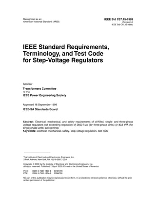
3.48 Type A step-voltage regulator: A step-voltage regulator in which the primary circuit is connected
directly to the shunt winding of the regulator. The series winding is connected to the shunt winding and, in
turn, via taps, to the regulated circuit, per Figure 1. In a Type A step-voltage regulator, the core excitation
varies because the shunt winding is connected across the primary circuit.
Figure 1—Schematic diagram of single-phase, Type A step-voltage regulator
3.49 Type B step-voltage regulator: A step-voltage regulator in which the primary circuit is connected, via
taps, to the series winding of the regulator. The series winding is connected to the shunt winding, which is
connected directly to the regulated circuit, per Figure 2. In a Type B step-voltage regulator, the core excita-
tion is constant because the shunt winding is connected across the regulated circuit.
Figure 2—Schematic diagram of single-phase, Type B step-voltage regulator
3.50 voltage regulating device: A voltage sensitive device that is used on an automatically operated voltage
regulator to control the voltage of the regulated circuit.
6 Copyright © 2000 IEEE. All rights reserved.
13. IEEE
TEST CODE FOR STEP-VOLTAGE REGULATORS Std C57.15-1999
4. Service conditions
4.1 Usual service conditions
Apparatus conforming to this standard shall be suitable for operation at rated kilovolt-amperes under the
service conditions given in 4.1.1 through 4.1.6.
4.1.1 Temperature
a) If air-cooled, the temperature of the cooling air (ambient temperature) does not exceed 40 °C, and
the average temperature of the cooling air for any 24 h period does not exceed 30 °C.
b) If water-cooled, the temperature of the cooling water (ambient temperature) does not exceed 30 °C,
and the average temperature of the cooling water for any 24 h period does not exceed 25 °C.
(Minimum water temperature shall not be lower than 1 °C, unless the cooling water includes anti-
freeze suitable for –20 °C operation.)
c) The top-liquid temperature of the regulator (when operating) shall not be lower than –20 °C.
(Starting temperatures below –20 °C are not considered as usual service conditions.)
4.1.2 Altitude
The altitude does not exceed 1000 m (3300 ft).
4.1.3 Supply voltage
The supply voltage wave shape shall be approximately sinusoidal, and the phase voltages supplying a poly-
phase regulator shall be approximately equal in magnitude and time displacement.
4.1.4 Load current
The load current shall be approximately sinusoidal. The harmonic factor shall not exceed 0.05 per unit.
Harmonic factor is defined IEEE Std C57.12.80-1978.
4.1.5 Outdoor operation
Unless otherwise specified, regulators shall be suitable for outdoor operation.
4.1.6 Tank or enclosure finish
Temperature limits and tests shall be based on the use of a nonmetallic pigment surface paint finish.
NOTE—Metallic flake paints, such as aluminum, zinc, and so forth, have properties that increase the temperature rise of
regulators, except in direct sunlight.
4.2 Loading at other than rated conditions
IEEE Std C57.95-1984 provides guidance for loading at other than rated conditions including
a) Ambient temperatures higher or lower than the basis of rating.
b) Short-time loading in excess of nameplate kVA with normal life expectancy.
c) Loading that results in reduced life expectancy.
Copyright © 2000 IEEE. All rights reserved. 7
14. IEEE
Std C57.15-1999 IEEE STANDARD REQUIREMENTS, TERMINOLOGY, AND
NOTE—IEEE Std C57.95-1984 is a guide rather than a standard. It provides the best known general information for the
loading of regulators under various conditions based on typical winding insulation systems, and is based upon the best
engineering information available at the time of preparation. The guide discusses limitations of ancillary components
other than windings that may limit the capability of regulators. When specified, ancillary components and other
construction features (cables, bushings, tap changers, oil expansion space, etc.) shall be supplied such that they in them-
selves will not limit the loading to less than the capability of the windings.
4.3 Unusual service conditions
Conditions other than those described in 4.1 are considered unusual service and, when present, should be
brought to the attention of those responsible for the design and application of the apparatus. Examples of
some of these conditions are discussed in 4.3.1 through 4.3.3.
4.3.1 Unusual temperature and altitude conditions
Regulators may be used at higher or lower ambient temperatures or at higher altitudes than specified in 4.1,
but special consideration must be given to these applications. Annex A and IEEE Std C57.95-1984 provide
information on recommended practices.
4.3.2 Insulation at high altitude
The dielectric strength of regulators that depend in whole or in part upon air for insulation decreases as the
altitude increases due to the effect of decreased air density. When specified, regulators shall be designed with
a larger air spacing, using the correction factors of Table 1, to obtain adequate air dielectric strength at
altitudes above 1000 m (3300 ft).
a) The insulation level at 1000 m (3300 ft) multiplied by the correction factor from Table 1 must not be
less than the required insulation level at the required altitude.
b) Bushings with additional length of creep distance shall be furnished where necessary for operation
above 1000 m (3300 ft).
Table 1—Dielectric strength correction factors for altitudes
greater than 1000 m (3300 ft)
Altitude Altitude correction
factor for dielectric
(m) (ft) strength
1000 3300 1.00
1200 4000 0.98
1500 5000 0.95
1800 6000 0.92
2100 7000 0.89
2400 8000 0.86
2700 9000 0.83
3000 10 000 0.80
3600 12 000 0.75
4200 14 000 0.70
4500 15 000 0.67
8 Copyright © 2000 IEEE. All rights reserved.
15. IEEE
TEST CODE FOR STEP-VOLTAGE REGULATORS Std C57.15-1999
4.3.3 Other unusual service conditions
Other unusual service conditions include the following:
a) Damaging fumes or vapors, excessive or abrasive dust, explosive mixtures of dust or gases, steam,
salt spray, excessive moisture or dripping water, etc.
b) Abnormal vibration, tilting, shock, or seismic conditions.
c) Ambient temperatures outside of normal range.
d) Unusual transportation or storage conditions.
e) Unusual space limitations.
f) Unusual maintenance problems.
g) Unusual duty or frequency of operation, impact loading.
h) Unbalanced alternating-current (ac) voltages or departure of ac systems voltages from a substan-
tially sinusoidal wave form.
i) Loads involving abnormal harmonic currents, such as those that may result where appreciable load
currents are controlled by solid-state or similar devices; such harmonic currents may cause excessive
losses and abnormal heating.
j) Specified loading conditions (kVA outputs and power factors) associated with multiwinding trans-
formers or autotransformers.
k) Excitation exceeding either 110% rated voltage or 110% rated V/Hz.
l) Planned short circuits as a part of regulator operating or relaying practice.
m) Unusual short-circuit application conditions differing from those described as usual in 5.8.
n) Unusual voltage conditions, including transient overvoltages, resonance, switching surges, etc., that
may require special consideration in insulation design.
o) Unusually strong magnetic fields.
NOTE—Solar magnetic disturbances may result in the flow of telluric currents in regulator neutrals.
p) Unusually high nuclear radiation.
q) Parallel operation.
NOTE—While parallel operation is not unusual, it is desirable that users advise the manufacturer if paralleling
with other regulators is planned, and the characteristics of the transformers or reactors so involved.
r) Direct current circulating within the regulator.
4.3.3.1 Voltage regulating device
The voltage regulating device, depending on its construction, may be sensitive to altitude considerations.
The manufacturer should be consulted where applications exceed 2000 m (6600 ft). Altitude of 4500 m
(15 000 ft) is considered a maximum for standard regulators. Dielectric strength correction factors for alti-
tudes greater than 1000 m (3300 ft) are shown in Table 1.
4.4 Frequency
Unless otherwise specified, regulators shall be designed for operation at a frequency of 60 Hz.
Copyright © 2000 IEEE. All rights reserved. 9
16. IEEE
Std C57.15-1999 IEEE STANDARD REQUIREMENTS, TERMINOLOGY, AND
5. Rating data
5.1 Cooling classes of regulators
5.1.1 Liquid-immersed air-cooled
a) Liquid-immersed self-cooled (Class ONAN)
b) Liquid-immersed self-cooled/forced-air-cooled (Class ONAN/ONAF)
5.1.2 Liquid-immersed water-cooled
a) Liquid-immersed water-cooled (Class ONWF)
b) Liquid-immersed water-cooled/self-cooled (Class ONWF/ONAN)
5.2 Ratings in kVA
Ratings (in kVA) for step-voltage regulators are continuous and based on not exceeding the temperature lim-
its covered in Table 2.
Ratings (in kVA) covered by this standard shall be expressed in the terms given in 5.2.1 and as specified in
5.2.2.
Table 2—Limits of temperature rise
Winding temperature rise Hottest-spot winding
Item Type of apparatusa
by resistance (°C) temperature rise (°C)
55 °C rise liquid immersed
55 65
(vented or sealed tank)
1
65 °C rise liquid immersed
65 80
(sealed tank)
Metallic parts in contact with or adjacent to the insulation shall not attain a temperature in excess of that
2
allowed for the hottest spot of the windings adjacent to that insulation.
3 Metallic parts other than those covered in item 2 shall not attain excessive temperature rises.
Where a regulator is provided with a sealed-tank, conservator, or gas-oil-seal system, the temperature
rise of the insulating oil shall not exceed 55 °C (55 °C rise unit) or 65 °C (65 °C rise unit) when
4 measured near the surface of the oil. The temperature rise of insulating oil in regulator not provided
with the oil preservation systems listed above shall not exceed 50 °C when measured near the exposed
surface of the oil.
aApparatus with specified temperature rise shall have an insulation system that has been proven by experience,
general acceptance, or an accepted test.
5.2.1 Terms in which rating is expressed
The rating of a step-voltage regulator shall be expressed in the following terms:
a) kVA
b) Number of phases
c) Frequency
d) Voltage
e) Current
f) Voltage range in percent (raise and lower)
10 Copyright © 2000 IEEE. All rights reserved.
17. IEEE
TEST CODE FOR STEP-VOLTAGE REGULATORS Std C57.15-1999
Regulators shall be approximately compensated for their internal regulation to provide the specified voltage
range at rating in kVA and with an 80% lagging power factor load.
5.2.2 Preferred kVA ratings
Preferred ratings of step-voltage regulators shall be based on operation at a frequency of 60 Hz and a voltage
range of 10% raise and 10% lower, as given in Table 3 and Table 4. .
5.2.3 Supplementary kVA ratings
In addition to their normal ratings, as defined in 5.2.2, regulators shall deliver rated kVA output without
exceeding the specified temperature rise at the operating voltage given in Table 5. Voltage regulators with
multitapped voltage transformers may be operated at nominal system voltages below the maximum rated
voltage, and may deliver rated line amperes without exceeding the temperature limits of Table 2.
5.3 Operating voltage limits
Regulators, including their controls, shall be suitable for operation within the following limits of voltage
provided that the rated load current is not exceeded:
a) A minimum input voltage of 97.75 V times the ratio of voltage transformer.
b) A maximum input voltage at rated load amperes of 1.05 times the rated input voltage of the regulator
or 137.5 V times the ratio of voltage transformer, whichever is less.
c) A maximum input voltage at no load of 1.10 times the rated input voltage of the regulator or 137.5 V
times the ratio of voltage transformer, whichever is less.
d) A minimum output voltage of 103.5 V times the ratio of voltage transformer.
e) A maximum output voltage of 1.1 times the rated voltage of the regulator or 137.5 V times the ratio
of voltage transformer, whichever is less.
f) The output voltage obtainable with a given input voltage is limited also by the regulator voltage
range.
Typical examples of the application of these rules to some common ratings of regulators are given in Table 8.
5.4 Supplementary continuous-current ratings
Single-phase step-voltage regulators up to 19.9 kV, inclusive, rated 668 A and below shall have the
continuous-current ratings or 668 A, whichever is less, on intermediate ranges of steps as shown in
Table 6.
Three-phase step-voltage regulators up to 13.8 kV, inclusive, rated 668 A and below, have the following
continuous-current ratings or 668 A, whichever is less, on intermediate ranges of steps as shown in Table 7.
5.5 Voltage supply ratios
Values of voltage supply ratios are given in Table 9. When a voltage supply ratio is specified that is not a
preferred value shown in Table 9, an ancillary transformer may be furnished in the unit or control to modify
the preferred ratio.
Copyright © 2000 IEEE. All rights reserved. 11
18. IEEE
Std C57.15-1999 IEEE STANDARD REQUIREMENTS, TERMINOLOGY, AND
Table 3—Preferred ratings for oil-immersed step-voltage regulators (single phase)
Nominal system BIL
kVA Line amperes
voltage (kV)
50 200
75 300
100 400
125 500
2400/4160Y 60
167 668
250 1000
333 1332
416 1665
50 100
75 150
100 200
125 250
4800/8320Y 75
167 334
250 500
333 668
416 833
38.1 50
57.2 75
76.2 100
114.3 150
167 219
7620/13 200Y 95 250 328
333 438
416 546
500 656
667 875
833 1093
69 50
138 100
207 150
13 800 95
276 200
414 300
552 400
72 50
144 100
216 150
288 200
14 400/24 940Y 150a 333 231
432 300
576 400
667 463
833 578
100 50
200 100
333 167
19 920/34 500Y 150
400 201
667 334
833 418
aLow-frequency test voltage 50 kV by induced test with neutral grounded.
12 Copyright © 2000 IEEE. All rights reserved.
19. IEEE
TEST CODE FOR STEP-VOLTAGE REGULATORS Std C57.15-1999
Table 4—Preferred ratings for oil-immersed step-voltage regulators (three phase)
Self-cooled Self-cooled/forced-cooled
Nominal system BIL
voltage (kV) kVA Line amperes kVA Line amperes
500 1155 625 1443
2400 45 750 1732 937 2165
1000 2309 1250 2887
500 667 625 833
2400/4160Y 60 750 1000 937 1250
1000 1334 1250 1667
500 577 625 721
4800 60 750 866 937 1082
1000 1155 1250 1443
500 219 625 274
750 328 938 410
7620/13 200Y 95 1000 437 1250 546
1500 656 2000 874
2000 874 2667 1166
500 209 625 261
750 313 937 391
1000 418 1250 523
7970/13 800Y 95
1500 628 2000 837
2000 837 2667 1116
2500 1046 3333 1394
500 125.5 625 156.8
750 188.3 937 235.4
1000 251 1250 314
14 400/24 940Y 150
1500 377 2000 502
2000 502 2667 669
2500 628 3333 837
500 83.7 625 104.5
750 125.5 937 156.8
1000 167 1250 209
19 920/34 500Y 150
1500 251 2000 335
2000 335 2667 447
2500 418 3333 557
500 62.8 625 78.5
750 94.1 937 117.6
1000 126 1250 157
26 560/46 000Y 250
1500 188 2000 251
2000 251 2667 335
2500 314 3333 419
500 41.8 625 52.5
750 62.8 937 78.5
1000 83.7 1250 105
39 840/69 000Y 350
1500 126 2000 167
2000 167 2667 223
2500 209 3333 278
Copyright © 2000 IEEE. All rights reserved. 13
20. IEEE
Std C57.15-1999 IEEE STANDARD REQUIREMENTS, TERMINOLOGY, AND
Table 5—Supplementary voltage ratings for regulators
Number of phases Rated voltage Operating voltage
Single-phase 7620 7200
2500 2400
4330 4160
5000 4800
Three-phase
8660 8320
13 200 12 470
13 800 13 200
Table 6—Supplementary continuous-current ratings for single-phase regulators
Range of voltage Continuous-current
regulation (%) rating (%)
10.0 100
8.75 110
7.5 120
6.25 135
5.0 160
Table 7—Supplementary continuous-current ratings for three-phase regulators
Range of voltage Continuous-current
regulation (%) rating (%)
10.0 100
8.75 108
7.5 115
6.25 120
5.0 130
5.6 Insulation levels
Regulators shall be designed to provide coordinated low-frequency and lightning impulse insulation levels
on line terminals, and low-frequency insulation levels on neutral terminals. The identity of a set of
coordinated levels shall be its basic impulse insulation level (BIL), as shown in Table 10.
NOTE—When single-phase regulators are connected in wye, the neutral of the regulator bank shall be connected to the
neutral of the system. A delta connection of the regulators is commonly recommended when the system is three-wire
ungrounded.
5.7 Losses
The losses specified by the manufacturer shall be the no-load (excitation) and total losses, as defined in 3.23
and 3.47, respectively.
14 Copyright © 2000 IEEE. All rights reserved.
21. Table 8—Typical examples of operating voltage limits including all operating voltage tolerances
Regulator voltage rating (V) Input voltage (V) Output voltage (V)
Nominal system Voltage Maximum at
voltage supply ratioa Maximum at
Maximum at rated-load
Single-phase Three-phase Minimum rated-load Minimum
no-load amperes or at
amperes
no-load
2400 2500 2500 20 1955 2625 2750 2070 2750
2400 / 4160Y 2500 — 20 1955 2625 2750 2070 2750
2400 / 4160Y — 4330 34.6 3380 4550 4760 3580 4760
4800 5000 5000 40 3910 5250 5500 4140 5500
Copyright © 2000 IEEE. All rights reserved.
7200 7620 — 60 5870 8000 8250 6210 8250
7200 — 8660 60 5870 8250 8250 6210 8250
4800 / 8320Y 5000 — 40 3910 5250 5500 4140 5500
TEST CODE FOR STEP-VOLTAGE REGULATORS
8320 — 8660 69.3 6775 9090 9525 7170 9525
12 470 13 800 13 800 104 10 170 14 300 14 300 10 760 14 300
7200 / 12 470Y 7620 — 60 5870 8000 8250 6210 8250
7200 / 12 470Y — 13 800 104 10 170 14 300 14 300 10 760 14 300
7620 / 13 200Y 7620 — 63.5 6210 8000 8380 6570 8380
7620 / 13 200Y 7620 — 66.3 6480 8000 8380 6860 8380
7620 / 13 200Y — 13 200 110 10 750 13 860 14 520 11 400 14 520
7960 / 13 800Y — 13 800 115 11 240 14 490 15 180 11 900 15 180
7960 / 13 800Y 7690 — 66.3 6480 8360 8760 6860 8760
13 200 13 800 13 800 110 10 750 14 490 15 125 11 400 15 125
14 400 13 800 12 800 120 11 730 14 490 15 180 12 420 15 180
14 400 / 24 940Y 14 400 — 120 11 730 15 120 15 840 12 420 15 840
19 920 / 34 500Y 19 920 — 166 16 230 20 920 21 910 17 180 21 910
14 400 / 24 940Y — 24 940 208 20 330 26 190 27 435 21 530 27 435
19 920 / 34 500Y — 34 500 287.5 28 100 36 225 37 950 29 760 37 950
26 560 / 46 000Y — 46 000 373.3 36 490 48 300 50 600 38 640 50 600
39 840 / 69 000Y — 69 000 575 56 210 72 450 75 900 59 510 75 900
aWhere
the listed potential ratio is provided, an additional ancillary transformer may be required.
NOTE—Example values are derived using procedures of 5.3.
15
Std C57.15-1999
IEEE
22. IEEE
Std C57.15-1999 IEEE STANDARD REQUIREMENTS, TERMINOLOGY, AND
Table 9—Values of voltage supply ratios
Voltage rating of regulator Values of voltage supply
ratios
Single-phase Three-phase
2500 2500 20, 20.8
— 4330 34.6, 36.1
5000 5000 40, 41.7
7620 — 60, 63.5
7690 — 66.3
— 8660 69.3, 72.2
— 13 200 110, 104
13 800 13 800 115, 110
14 400 — 120
19 920 — 166
— 24 940 208
— 34 500 287.5
— 46 000 383.3
— 69 000 575
Table 10—Interrelationships of dielectric insulation levels for regulators
used on systems with BIL ratings of 350 kV and below
Impulse levels
Low-frequency
voltage Full wave Chopped wave
BIL kV
insulation level
(kV rms) Minimum time
(kV crest) (kV crest)
to flashover (µs)
45 15 45 54 1.5
60 19 60 69 1.5
75 26 75 88 1.6
95 34 95 110 1.8
150 50 150 175 3.0
200 70 200 230 3.0
250 95 250 290 3.0
350 140 350 400 3.0
16 Copyright © 2000 IEEE. All rights reserved.
23. IEEE
TEST CODE FOR STEP-VOLTAGE REGULATORS Std C57.15-1999
5.7.1 Total losses
The total losses of a regulator shall be the sum of the no-load (excitation) and load losses.
5.7.2 Tolerance for losses
Unless otherwise specified, the losses represented by a test of a regulator shall be subject to the following
tolerances: the no-load losses of a regulator shall not exceed the specified no-load losses by more than 10%,
and the total losses of a regulator shall not exceed the specified total losses by more than 6%. Failure to meet
the loss tolerances shall not warrant immediate rejection but lead to consultation between purchaser and
manufacturer about further investigation of possible causes and the consequences of the higher losses.
NOTE—Since losses will differ at different operating positions of the regulator, care must be exercised in the consider-
ation of tap position with losses. Some styles of step-voltage regulators will exhibit appreciable change in load loss when
boosting versus bucking, or will exhibit appreciable change in no-load loss on alternate tap positions. See 5.7.3.
5.7.3 Determination of losses and excitation current
No-load (excitation) losses and exciting current shall be determined for the rated voltage and frequency on a
sine-wave basis, unless a different form is inherent in the operation of the apparatus.
Load losses shall be determined for rated voltage, current, and frequency and shall be corrected to a refer-
ence temperature equal to the sum of the limiting (rated) winding temperature rise by resistance from
Table 2 plus 20 °C.
Since losses may be very different at different operating positions and with various design options, losses
shall be considered in practice as the sum of no-load and load losses where
a) No-load loss is the average of no-load loss in the neutral and next adjacent boost position with rated
voltage applied to the shunt or series winding for regulators that do not include a series transformer.
NOTE—It will be apparent, in the case of a Type B step-voltage regulator that is on the next adjacent boost
position, that the excitation voltage applied at the source terminal will be higher at the shunt winding. Care
must be exercised to assure that rated excitation is present on the shunt winding; this may be accomplished by
exciting the regulator from the load terminal.
b) No-load loss is reported for neutral position, maximum boost position, and position adjacent to
maximum boost position for regulators that include a series transformer.
c) Load loss is the average load loss in both the maximum and adjacent-to-maximum buck positions,
and the maximum and adjacent-to-maximum boost positions (that is, four positions) with rated
current in the windings.
5.8 Short-circuit requirements
5.8.1 General
Step-voltage regulators shall be designed and constructed to withstand the mechanical and thermal stresses
produced by external short circuits of 25 times the base rms symmetrical rated load current.
a) The short-circuit current shall be assumed to be displaced from zero insofar as determining the
mechanical stresses. The maximum peak value of the short-circuit current that the regulator is
required to withstand is equal to 2.26 times the required rms symmetrical short-circuit current.
b) The short-circuit current shall be assumed to be a duration of 2 s to determine the thermal stresses.
It is recognized that short-circuit withstand capability can be adversely affected by the cumulative effects of
repeated mechanical and thermal over-stressing, as produced by short-circuits and loads above the name-
Copyright © 2000 IEEE. All rights reserved. 17
24. IEEE
Std C57.15-1999 IEEE STANDARD REQUIREMENTS, TERMINOLOGY, AND
plate rating. Since means are not available to continuously monitor and quantitatively evaluate the degrading
effects of such duty, short-circuit tests, when required, should be performed prior to placing the regulator in
service. It is recommended that current-limiting reactors be installed, when necessary, to limit the short-
circuit current to a maximum of 25 times the normal full-load current.
5.8.2 Mechanical capability demonstration
It is not the intent of this subclause that every regulator design be short-circuit tested to demonstrate
adequate construction. When specified, tests of short-circuit mechanical capability shall be performed as
described in 8.8.
5.8.3 Thermal capability of regulators for short-circuit conditions
The temperature of the conductor material in the windings of regulators under the short-circuit conditions
specified in 5.8.1 item b), as calculated by methods described in 8.9.4, shall not exceed 250 °C for a copper
conductor or 200 °C for an EC aluminum conductor. A maximum temperature of 250 °C shall be allowed for
aluminum alloys that have resistance to annealing properties at 250 °C, equivalent to EC aluminum at
200 °C, or for application of EC aluminum where the characteristics of the fully annealed material satisfy
the mechanical requirements. In setting these temperature limits, the following factors were considered:
a) Gas generation from oil or solid insulation
b) Conductor annealing
c) Insulation aging
5.9 Tests
Except as specified in 5.9.1, 5.9.2, and Clause 8, tests shall be performed as specified in IEEE Std
C57.12.00-1993 and in IEEE Std C57.12.90-1999. Tests are divided into two categories: routine and design.
Routine tests are made for quality control by the manufacturer to verify during production that the product
meets the design specifications. Design tests are made to determine the adequacy of the design of a particu-
lar type, style, or model of equipment or its component parts to meet its assigned rating under normal service
conditions or under special conditions if specified.
5.9.1 Routine tests
The routine tests given in the following list shall be made on all regulators. The order of listing does not nec-
essarily indicate the sequence in which the tests shall be made.
a) Resistance measurements of all windings
b) Ratio tests on all tap connections
c) Polarity test
d) No-load (excitation) loss at rated voltage and rated frequency
e) Excitation current at rated voltage and rated frequency
f) Impedance and load loss at rated current and rated frequency
g) Lightning impulse tests specified in 8.6.3
h) Applied-voltage tests
i) Induced-voltage tests
j) Insulation power factor tests
k) Insulation resistance tests
18 Copyright © 2000 IEEE. All rights reserved.
25. IEEE
TEST CODE FOR STEP-VOLTAGE REGULATORS Std C57.15-1999
5.9.2 Design tests
The following design tests are made only on representative apparatus to substantiate the ratings assigned to
all other apparatus of basically the same design. These tests are not intended to be used as a part of normal
production. The applicable portion of these design tests may also be used to evaluate modifications of a
previous design and to assure that performance has not been adversely affected. Test data from previous sim-
ilar designs may be used for current designs, where appropriate. Once made, the tests need not be repeated
unless the design is changed so as to modify performance.
5.9.2.1 Thermal tests
Temperature design tests shall be made on one unit of a given rating produced by a manufacturer as a record
that this design meets the temperature rise requirement for a 55 °C or 65 °C rise unit. Temperature tests shall
be made at the positions that produce the highest total losses at rated load current for the normal 100% rat-
ing, supplementary kVA rating (see 5.2.3) and the 160% or 668 A rating (see 5.4). When a regulator is sup-
plied with ancillary cooling equipment to provide higher kVA ratings, temperature tests shall be made at
those ratings also. Temperature tests shall be made for all kVA ratings given on the nameplate. Tests shall be
made in accordance with 8.7.
5.9.2.2 Lightning impulse tests
Design lightning impulse tests shall be made on one unit of a given rating produced by a manufacturer for
the purpose of demonstrating the adequacy of insulating materials breakdown and spacing under normal
conditions. Tests shall be made in accordance with 8.6.2. Impulse tests are to be followed by the application
of the applied and induced voltage tests.
5.9.2.3 Short-circuit tests
Short-circuit tests shall be made on one unit of a rating produced by a manufacturer for the purpose of
demonstrating that the unit meets the thermal and mechanical requirements of 5.8. Where lower kVA and
voltage ratings have the same design configuration, core and coil framing, and clamping as the unit tested,
short-circuit tests are not required, and it is adequate to show by calculation that the mechanical forces are
equal or less than the unit tested and the temperature rise of the conductor meets the criteria. Tests are to be
made in accordance with 8.8.
6. Construction
6.1 Bushings
Regulators shall be equipped with bushings with an insulation level not less than that of the winding terminal
to which they are connected, unless otherwise specified.
Bushings for use in regulators shall have impulse and low-frequency insulation levels as listed in Table 11.
6.2 Terminal markings
6.2.1 Terminal markings for step-voltage regulators
Regulator terminals that are connected to the load shall be designated by an L, and those that are connected
to the source shall be designated by an S. For example, in the case of a single-phase regulator, the terminals
Copyright © 2000 IEEE. All rights reserved. 19
26. IEEE
Std C57.15-1999 IEEE STANDARD REQUIREMENTS, TERMINOLOGY, AND
Table 11—Electrical characteristics of regulator bushings (kV)
Outdoor bushings Indoor bushingsa
Impulse-full 60 Hz Impulse-full
Regulator
60 Hz withstand wave dry withstand wave dry
BIL
withstand 1 min dry withstand
(kV)
1 min dry 10 s wetb kV crest kV crest
kV crest
(kV rms) (kV rms) (1.2 × 50 µm) (1.2 × 50 µs)
45 15 13 45 20 45
60 21 20 60 24 60
75 27 24 75 30 75
95 35 30 95 50c 110c
150 60 50 150 60 150
200 80 75 200 80 200
250 105 95 250 — —
350 160 140 350 — —
aWet withstand values are based on water resistivity of 180 Ω·m (7000 Ω·in) and precipitation rate
of 0.10 mm/s (0.2 in/min).
bIndoor bushings are those intended for use in indoor regulators. Indoor bushing test values do not
apply to bushings used primarily for mechanical protection of insulated cable leads. A wet test value
is not assigned to indoor bushings.
cSmall indoor regulators may be supplied with bushings for a dry test of 38 kV and impulse test of
95 kV.
shall be identified by S, L, and SL. In the case of a three-phase regulator, the terminals shall be identified S1,
S2, S3, L1, L2, L3, and, if a neutral is provided, S0L0.
Single-phase regulators, when viewed from the top, shall have the S terminal on the left, followed in
sequence in a clockwise direction by the L terminal and the neutral terminal SL, as shown in Figure 3.
Figure 3—Single-phase regulators
For three-phase regulators, when facing the regulator on the source side, the S1 terminal shall be in front on
the right, and the L1 terminal shall be directly behind the S1 terminal, as shown in Figure 4(a), or the S1 ter-
minal shall be in front on the right, and the L1 terminal shall be directly to the left of the S1 terminal, as
shown in Figure 4(b). The other terminals shall be located as shown in Figure 4.
20 Copyright © 2000 IEEE. All rights reserved.
27. IEEE
TEST CODE FOR STEP-VOLTAGE REGULATORS Std C57.15-1999
NOTE—The dotted line shows the location of the control compartment and the tap-changing under load equipment.
The dotted circle shows alternate location of neutral bushing.
Figure 4—Three-phase regulators
6.3 Diagram of connections
The manufacturer shall furnish, with each voltage regulator, complete diagrams showing the leads and
internal connections and their markings, including polarity markings, and the voltages obtainable with the
various connections. These diagrams shall be inscribed on and be part of the nameplate.
6.4 Nameplates
Two durable metal nameplates shall be furnished with each voltage regulator and shall be affixed to the main
tank and on the front of the control cabinet. Unless otherwise specified, they shall be of corrosion-resistant
material. The nameplates shall show, at a minimum, the ratings and other essential operating data as
specified as follows:
a) Manufacturer’s name
b) Type and form designation or the equivalent
c) Class
d) Serial number
e) Month and year of manufacturer (not coded)
f) Number of phases
g) Rated kVA
h) Rated current
i) Supplementary continuous-current ratings
j) Rated voltage
k) Voltage transformer ratio
l) Rated range of regulation
Copyright © 2000 IEEE. All rights reserved. 21
28. IEEE
Std C57.15-1999 IEEE STANDARD REQUIREMENTS, TERMINOLOGY, AND
m) Rated frequency
n) Impulse level, full wave in kilovolts (kV)
o) Untanking weight
p) Total weight
q) Insulating fluid type
r) Volume of insulating fluid
s) Conductor material
t) Average winding rise in degrees Celsius (°C)
u) Diagrams as specified in 6.3
v) Installation and operating instructions reference
6.5 Tank construction
Accepted techniques for tank construction as it relates to oil-gas space systems are the conservator
(expansion tank), gas-oil sealed, nonsealed, and sealed tank systems.
6.6 Tank grounding provisions
6.6.1 Maximum continuous rating less than 300 A
Tank grounding provisions shall consist, at a minimum, of one steel pad with a 0.5 in – 13 NC tapped hole,
11 mm (0.44 in) deep and located near the bottom of the tank.
6.6.2 Maximum continuous rating 300 A or greater
Tank grounding provision shall consist, at a minimum, of one unpainted copper-faced steel or stainless steel
pad, 50 mm (2 in) × 90 mm (3.5 in), with two holes horizontally spaced on 44.5 mm (1.75 in) centers, tapped
for 0.5 in – 13 NC thread and located near the bottom of the tank. Minimum thread depth of each hole shall
be 13 mm (0.5 in). Minimum thickness of the copper facing, when used, shall be 0.4 mm (0.015 in).
6.7 Components and accessories
6.7.1 Single-phase and three-phase step-voltage regulators
6.7.1.1 Components for full automatic control and operation
a) Control system and cabinet
b) Current and voltage transformers or the equivalent for supplying the control system
c) Tap-changer drive motor
d) Internal power supply for drive motor
e) Provision for disconnecting control power supply
f) Tap-changer position indicator
6.7.1.2 Accessories for single-phase step-voltage regulators
a) Nameplate.
b) Lifting lugs.
c) Provision for oil drainage and sampling.
d) Tank grounding provision.
22 Copyright © 2000 IEEE. All rights reserved.
29. IEEE
TEST CODE FOR STEP-VOLTAGE REGULATORS Std C57.15-1999
e) Bushing terminals shall be either clamp-type or threaded stud, depending on the nameplate line cur-
rent ratings as shown in Table 12.
The clamp-type terminals shall have at least the conductor range stated and shall be capable of
accepting an aluminum or copper conductor. Threaded stud sizes shown are minimum. The user has
the responsibility of selecting the proper conductor size for use in the clamp-type terminals. When
selecting the conductor size, the user should consider factors such as additional current carrying
capability with reduced regulation (see 5.4), supplementary kVA ratings (see 5.2.3) and loading at
other than rated conditions (see 4.2).
f) Support lugs for pole mounting, when provided, shall conform to one of the alternatives required by
ANSI C57.12.20-1997.
g) Liquid level indicator.
Table 12—Bushing terminal applications
Nameplate line current rating Conductor size range or
(A) threaded stud
150 or less #8–4/0
151–300 #2– 477 kCM
301–668 #2– 800 kCM
669–1200 1-1/8–12 UNF-2A
1201–2000 1-1/2–12 UNF-2A
6.7.1.3 Accessories for three-phase step-voltage regulators
a) Nameplate
b) Liquid level indicator
c) Provision for oil draining and sampling
d) Provision for oil filtering
e) Provision for thermometer
f) Lifting lugs
g) Clamp-type terminals in accord with single-phase criteria [see 6.7.1.2(e)]
h) Handholes or openings to permit inspection of core and coil and load tap-changer
i) Tank grounding provision
7. Other requirements
Certain specific applications have regulator requirements not covered in Clause 4, Clause 5, or Clause 6.
Clause 7 comprises descriptions of the most frequently used requirements for such regulators. They shall be
provided only when specified in conjunction with the requirements of Clause 4 through Clause 6.
Information in the following subclauses may be specified for some applications.
7.1 Other supplementary continuous-current ratings
When specified, other supplementary continuous-current ratings, 668 A maximum, for three-phase regula-
tors rated 8660 V and 13 200 V shall be provided as shown in Table 13 (see 5.4).
Copyright © 2000 IEEE. All rights reserved. 23
30. IEEE
Std C57.15-1999 IEEE STANDARD REQUIREMENTS, TERMINOLOGY, AND
Table 13—Other supplementary continuous-current ratings for three-phase regulators
Range of voltage regulation Continuous-current ratings
(%) (%)
10.0 100
8.75 110
7.5 120
6.25 135
5.0 160
7.2 Other short-circuit capability
When specified, either of the following short-circuit capabilities for regulators shall be provided:
a) Three-phase regulators rated 1500 kVA and below, capable of withstanding rms symmetrical short-
circuit current of 40 times base rated load current or 20 000 A, whichever is less, for 0.8 s without
damage.
b) Single-phase regulators rated 500 kVA and below, capable of withstanding rms symmetrical short-
circuit current of 40 times the base rated load current or 20 000 A, whichever is less, for 0.8 s
without damage.
The initial current shall be assumed to be displaced from zero insofar as determining the mechanical
stresses. The maximum crest value of the short-circuit current that the regulator is required to withstand is
equal to 2.26 times the required rms symmetrical short-circuited current.
7.3 Other components and accessories
When specified, the other components and accessories listed in 7.3.1 and 7.3.2 may be provided.
7.3.1 For all regulators
a) Control cabinet removable for remote control operation [to 9 m (30 ft) from the regulator]
b) Voltage limit control
c) Reverse power flow relay
d) Remote voltage reduction control
7.3.2 For three-phase regulators
a) Hand operation crank
b) Load tap-changing mechanisms in separate compartment
c) 5 A secondary rating for current transformer
d) Remote position indicator
NOTE—For Selsyn-type systems, care shall be exercised to assure that the conductor size is commensurate with the
distance used.
24 Copyright © 2000 IEEE. All rights reserved.