

Recommandé
Contenu connexe
En vedette
En vedette (19)
Similaire à Power plant
Similaire à Power plant (20)
Dernier
Dernier (20)
Power plant
- 1. Steam Power Plant UNIT 2 STEAM POWER PLANT Structure 2.1 Introduction Objectives 2.2 Basic Consideration in the Analysis of Power Cycles 2.3 Steam Generator 2.4 Super Heater 2.5 Feed Water Heater 2.6 Furnaces 2.7 Energy Performance Assessment of Boilers 2.8 Steam Turbines 2.9 Condenser 2.10 Cooling Tower 2.11 Steam Power Station Control 2.12 Summary 2.13 Key Words 2.14 Answers to SAQs 2.1 INTRODUCTION Two important area of application of thermodynamics are power generation and refrigeration. Both power generation and refrigeration are usually accomplished by a system that operates on a thermodynamics cycle. Thermodynamics cycles can be divided into two generation categories : (a) Power Cycles (b) Refrigeration Cycles The devices or systems used to produce a net power output are often called engines and the thermodynamics cycles they operate on are called power cycle. The devices or systems use to produce refrigeration are called refrigerator, air conditioners or heat pumps and the cycles they operates on are called refrigeration cycles. Thermodynamic cycles can be categorized as : (a) Power cycles or Refrigeration cycles. (b) Gas Cycles or Vapor Cycles : In gas cycles, the working fluid remains in the gaseous phase throughout the entire cycle, where as in vapor cycles the working fluid exists in the vapor phase during one part of the cycle and in the liquid phase during another part. (c) Closed Cycles or Open Cycles : In closed cycles, the working fluid is returned to the initial state at the end of the cycle and is re-circulated. In open cycle, the working fluid is renewed at the end of each cycle instead of being re-circulated. 21
- 2. Power Plant Engineering Objectives After studying this unit, you should be able to know steam generator, steam turbine, and describe cooling towers and condensers. 2.2 BASIC CONSIDERATION IN THE ANALYSIS OF POWER CYCLES Actual Cycle The cycles encountered in actual devices are difficult to analyze because of the presence of complicating effects, such as friction and the absence of sufficient time for establishment of the equilibrium conditions during the cycle. Ideal Cycle When the actual cycle is stripped of all the internal irreversibilities and complexities, we end up with a cycle that resembles the actual cycle closely but is made up totally of internally reversible processes. Such a cycle is called an Ideal cycle. Heat Engines Heat engines are designed for the purpose of converting other form of energy to work and their performance is expressed as thermal efficiency. Wnet th Qin The Idealization and Simplification (a) The cycle does not involve any friction. (b) All expansion and compression process take place in a quasi- equilibrium manner. (c) The pipe connecting the various component of a system are well insulated and heat transfer and pressure drop through them are negligible. Carnot Cycle The Carnot cycle is composed of 4 totally reversible processes : (a) Isothermal heat addition at high temperature (TH). (b) Isentropic expansion from high temperature to low temperature. (c) Isothermal heat rejection at low temperature (TL). (d) Isentropic compression from low temperature to high temperature. TL Thermal efficiency of Carnot cycle = th, carnot 1 TH The Carnot Vapor Cycle (a) A steady-flow Carnot cycle executed with the saturation dome of a pure substance is shown in Figures 2.1(a) and (b). The fluid is heated reversibly and isothermally in a boiler (process 1-2), expanded isentropically in a turbine (process 2-3), condensed reversibly and isothermally in a condenser (process 3-4) and compressed isentropically by a compressor to the initial state (process 4-1). 22
- 3. (b) The Carnot cycle is not a suitable model for vapor power cycle because it Steam Power Plant cannot be approximated in practice. T 2 1 4 3 s (a) T 2 1 4 3 s (b) Figure 2.1 : Carnot Cycle Rankine Cycle : The Ideal Cycle for Vapor Power Cycle (a) The impracticalities associated with Carnot cycle can be eliminated by superheating the steam in the boiler and condensing it completely in the condenser. This cycle that results is the Rankine cycle, which is the ideal cycle for vapor power plants. The construct of power plant and T-s diagram is shown in Figures 2.2(a) and (b). qin Boiler 3 2 W turb,out Turbi wpump,in ne Pump 4 qout 1 Condenser (a) T 3 qin W turb,out 2 1 4’ qout wpunp,in s (b) Figure 2.2 : Rankine Cycle 23
- 4. Power Plant Engineering (b) The ideal Rankine cycle dose not involve any internal irreversibilities (c) The Rankine cycle consists of the following four processes : 1-2 : Isentropic compression in pump (compressors) 2-3 : Constant pressure heat addition in boiler 3-4 : Isentropic expansion in turbine 4-1 : Constant pressure heat rejection in a condenser Process 1-2 Water enters the pump at state 1 as saturated liquid and is compressed isentropically to the operating pressure of the boiler. The water temperature increases somewhat during this isentropic compression process due to slight decrease in the specific volume of the water. The vertical distance between state 1 and 2 on the T-s diagram is greatly exaggerated for clarity. Process 2-3 Water enters the boiler as a compressed liquid at state 2 and leaves as a superheated vapor at state 3. The boiler is basically a large heat exchanger where the heat originating from combustion gases, is transferred to the water essentially at constant pressure. The boiler together with the section where the steam is superheated (the superheater), is often called the steam generator. Process 3-4 The superheated vapor at state 3 enters the turbine, where it expands isentropically and produces work by rotating the shaft connected to an electric generator. The pressure and the temperature of the steam drops during this process to the values at state 4, where steam enters the condenser Process 4-1 At this state, the steam is usually a saturated liquid-vapor mixture with a high quality. Steam is condensed at constant pressure in the condenser which is basically a large heat exchanger, by rejecting heat to a cooling medium from a lake, or a river. Steam leaves the condenser as saturated liquid and enters the pump, completing the cycle. Energy Analysis of the Ideal Rankine Cycle All four components associated with the Rankine cycle (the pump, boiler, turbine and condenser) are steady-flow devices, and thus all four processes that make up the Rankine cycle can be analyzed as steady-flow process. The steady flow equation per unit mass of steam reduces to (qin qout ) (win wout ) he hi (kJ/kg) Pump (q = 0) : wpump, in (h2 h1 ) v ( P2 P ) 1 where h1 h f @ p1 and v v1 v f @ p1 Boiler (w = 0) : qin h3 h2 Turbine (q = 0) : wturbine, out (h3 h4 ) 24
- 5. Condenser (w = 0) Steam Power Plant qout h4 h1 The thermal efficiency of the Rankine cycle is determine from wnet q th 1 out qin qin where wnet qin qout wturbine, out wpump, in Deviation of Actual Vapor Power Cycle from Idealized Ones The actual vapor power cycle differs from the ideal Rankine cycle, as a result of irreversibilites in various components. Fluid friction and heat loss to the surroundings are the two common sources of irreversibilites. Fluid friction causes pressure drop in the boiler, the condenser and the piping between various components. Also the pressure at the turbine inlet is somewhat lower than that at the boiler exit due to the pressure drop in the connecting pipes. To compensate for these pressure drops, the water must be pumped to a sufficiently higher pressure than the ideal cycle. This requires a large pump and larger work input to the pump, are shown in Figures 2.3(a) and (b). T IDEAL CYCLE Pressure drop in Pressure drop the boiler in the pump 3 2 Irreversibility in the turbine ACTUAL CYCLE 4 1 Pressure drop in the condenser s (a) T 3 2a 2s 1 4s 4a s (b) Figure 2.3 : Vapour Power Cycle The other major source of irreversibility is the heat loss from the steam to the surrounding as the steam flows through various components. Particular importance is the irreversibilites occurring within the pump and the turbine. A pump requires a greater work input, and a turbine produces a smaller 25
- 6. Power Plant Engineering work output as a result of irreversibilties. Under the ideal condition the flow through these devices is isentropic. The deviation of actual pumps and turbine from the isentropic ones can be accurately accounted by isentropic efficiencies, define as : ws h2 s h1 p wa h2a h1 wa h3 h4a T ws h3 h4 s How can We Increase the Efficiency of the Rankine cycle? Than Rankine cycle efficiency can be increased by increasing average temperature at which heat is transferred to the working fluid in the boiler or decreasing the average temperature at which heat is rejected from the working fluid in the condenser. That is, the average fluid temperature should be as high as possible during heat addition and as low as possible during heat rejection. The three ways by which efficiency of the Rankine cycle can be increased are : (a) Lowering the condenser pressure (Lowers Tlow, av). (b) Superheating the steam to high temperatures (Increases Thigh, av). (c) Increasing the boiler pressure (Increases Thigh, av). Lowering the Condenser Pressure (Lowers Tlow, av) Steam exists as a saturated mixture in the condenser at the saturation temperature corresponding to the pressure inside the condenser. Therefore, lowering the operating pressure of the condenser automatically lower the temperature of the steam, and thus the temperature at which heat is rejected. The effect of lowering the condenser pressure on the Rankine cycle efficiency is illustrated in below Figure 2.4. T 3 2 2’ 4 1 P’4 < P4 1’ 4’ Increase in wnet s Figure 2.4 : Rankine Cycle Drawback of lowering the condenser pressure is increase in the moisture content of the steam at the final stages of the turbine. The presence of large quantities of moisture is highly undesirable in turbines because it decreases the turbine efficiency and erodes the turbine blades. Superheating the Steam to High Temperatures (Increases Thigh, av) The average temperature at which heat is added to the steam can be increased without increasing the boiler pressure by superheating the steam to high temperatures. The effect of superheating on the performance of 26 vapor power cycle is illustrated on a T-s diagram as shown in Figure 2.5.
- 7. Superheating the steam to higher temperatures has very desirable effect : It Steam Power Plant decreases the moisture content of the steam at the turbine exit as can be seen in T-s diagram as shown in Figure 2.6. The temperature to which steam can be superheated is limited by metallurgical consideration. T Increase in wnet 3’ 3 2 1 4 4’ Figure 2.5 : Vapour Power Cycle T 3’ 3 Increase in w net Increase in wnet 2’ 2 1 4’ 4 s Figure 2.6 : Vapour Power Cycle Increasing the Boiler Pressure (Increases Thigh, av) The average temperature during the heat addition process is to increase the operating pressure of the boiler, which automatically raises the temperature at which boiling take place. This, in turn, raises the average temperature at which heat is added to the steam and thus raises the thermal efficiency of the cycle. The Ideal Reheat Rankine Cycle The efficiency of the Rankine cycle can increase by expanding the steam in the turbine in two stages, and reheating it in between. Reheating is a practical solution to the excessive moisture problem in turbines, and it is commonly used in modern steam power plants. The schematic and T-s diagram of the ideal reheat Rankine cycle is shown in Figures 2.7(a) and (b). The ideal reheat Rankine cycle differs from the simple ideal Rankine cycle in that the expansion process take place in two stages. In first stage (the high-pressure turbine), steam is expanded isentropically to an intermediate pressure and sent back to the boiler where it is reheated at constant pressure, usually to the inlet temperature of the first turbine stage. Steam then expands isentropically in the second stage (low-pressure turbine) to the condenser pressure. 27
- 8. Power Plant Engineering 3 High - p Low p Boiler turbine trine Reheater 4 P 4 = P5 = Preheat 6 5 Condenser 2 Pump (a) Reheating T High-pressure turbine 3 4 2’ Low pressure 4 2 1 6 s (b) Figure 2.7 : Ideal Reheat Rankine Cycle Thus the total heat input and the total work output for a reheat cycle become : qin qprimary qreheat (h3 h2 ) (h5 h4 ) wturbine, out wturbine, I wturbine, II (h3 h4 ) (h5 h6 ) The Ideal Regenerative Rankine Cycle As shown in Figure 2.8, T-s diagram for the Rankine cycle shows that heat transferred to the working fluid during process 2-2 at a relatively low temperature. This lowers the average heat-addition temperature and thus the cycle efficiency. To remedy this shortcoming, the temperature of the liquid leaving the pump (called feedwater) before it enters the boiler need to be increased. T Steam exiting Low- boiler temperature heat addition 2’ Steam entering boiler 2 1 4 s Figure 2.8 : Ideal Regenerative Rankine Cycle 28
- 9. Another way of increasing the thermal efficiency of the Rankine cycle is by Steam Power Plant regeneration. During a regeneration process, liquid water (feedwater) leaving the pump is heated by steam bled off the turbine at some intermediate pressure in devices called feedwater heaters. There are two type of feedwater Heaters : (a) Open Feedwater Heater (b) Closed Feedwater Heater Open Feedwater Heater An open (or direct-contact) feedwater heater is basically a mixing chamber, where the steam extracted from the turbine mixes with the feedwater exiting the pump. Ideally, the mixture leaves the heater as a saturated liquid at the heater pressure. The schematic of a steam power plant with one open feedwater heater and the T-s diagram of the cycle are shown in the Figure 2.9. The heat and work interaction of a regenerative Rankine cycle with one feedwater heater can be expressed per unit mass of steam flowing through the boiler as follows : qin h5 h4 qout (1 y) (h7 h1 ) wturbine, out (h5 h6 ) (1 y) (h6 h7 ) wturbine, in (1 y) wpump I, in wpump II, in m6 where y m5 wpump I, in v1 ( p2 p1 ) wpump II, in v3 ( p4 p3 ) 5 Boiler Turbine y Open 6-y 1-y FWH 4 2 Condenser Pump II Pump 1 (a) T 5 4 6 3 3 1 7 s (b) Figure 2.9 : Steam Power Plant 29
- 10. Power Plant Engineering The thermal efficiency of the Rankine cycle increases as a result of regeneration. This is because regeneration raises the average temperature at which heat is transferred to the steam in the boiler by raising the temperature of the water before it enters the boiler. Closed Feedwater Heaters Another type of feedwater heater used is steam power plants is the closed feedwater heater in which heat is transferred from the extracted steam to the feedwater without any mixing taking place. The two streams now can be at different pressure, since they do not mix. The schematic of a steam power plant with one closed feedwater heater and the T-s diagram of the cycle are shown in Figure 2.10. 6 Boiler Turbine Mixing 7 chambe 8 Closed r 9 FWH 5 2 4 3 Condenser Pump II Pump 1 (a) T 6 4 5 9 7 2 3 1 8 s (b) Figure 2.10 : Steam Power Plant 2.3 STEAM GENERATOR Steam is an important medium of producing mechanical energy. Steam has the advantage that, it can be raised from water which is available in abundance it does not react much with the materials of the equipment of power plant and is stable at the temperature required in the plant. Steam is used to drive steam engines, steam turbines etc. Steam power station is most suitable where coal is available in abundance. Thermal electrical power generation is one of the major methods. Out of total power developed in India about 60% is thermal. For a thermal power plant the range of pressure may vary from 10 kg/cm2 to super critical pressures and the range of temperature may be from 250°C to 650°C. 30
- 11. 2.3.1 Essentials of Steam Power Plant Equipment Steam Power Plant A steam power plant must have following equipment : (a) A furnace to burn the fuel. (b) Steam generator or boiler containing water. Heat generated in the furnace is utilized to convert water into steam. (c) Main power unit such as an engine or turbine to use the heat energy of steam and perform work. (d) Piping system to convey steam and water. In addition to the above equipment the plant requires various auxiliaries and accessories depending upon the availability of water, fuel and the service for which the plant is intended. The flow sheet of a thermal power plant consists of the following four main circuits : (a) Feed water and steam flow circuit. (b) Coal and ash circuit. (c) Air and gas circuit. (d) Cooling water circuit. A steam power plant using steam as working substance works basically on Rankine cycle. Steam is generated in a boiler, expanded in the prime mover and condensed in the condenser and fed into the boiler again. The different types of systems and components used in steam power plant are as follows : (a) High pressure boiler (b) Prime mover (c) Condensers and cooling towers (d) Coal handling system (e) Ash and dust handling system (f) Draught system (g) Feed water purification plant (h) Pumping system (i) Air preheater, economizer, super heater, feed heaters. Figure 2.11 shows a schematic arrangement of equipment of a steam power station. Coal received in coal storage yard of power station is transferred in the furnace by coal handling unit. Heat produced due to burning of coal is utilized in converting water contained in boiler drum into steam at suitable pressure and temperature. The steam generated is passed through the superheater. Superheated steam then flows through the turbine. After doing work in the turbine the pressure of steam is reduced. Steam leaving the turbine passes through the condenser which is maintained the low pressure of steam at the exhaust of turbine. Steam pressure in the condenser depends upon flow rate and temperature of cooling water and on effectiveness of air removal equipment. Water circulating through the condenser may be taken from the various sources such as river, lake or sea. If sufficient quantity of water is not available the hot water coming out of the condenser may be cooled in cooling towers and circulated again through the condenser. Bled steam taken from the turbine at suitable extraction points is sent to low pressure and high pressure water heaters. 31
- 12. Power Plant Engineering Coal To chimney Storag e Flue gases Air Cool Air preheater handing Flue gases plant 3-phase supply Feed water Econo- miser Ash Ash Main valve handing Boiler Super Storage plant Turbine Generator Flue heater gases Steam High pressure Exhaust heater Condensate steam Boiler feed extraction pump pump Condenser Low presser heater Circulation water pump Cooling tower River or canal Figure 2.11 : Steam Power Plant Air taken from the atmosphere is first passed through the air pre-heater, where it is heated by flue gases. The hot air then passes through the furnace. The flue gases after passing over boiler and superheater tubes, flow through the dust collector and then through economiser, air pre-heater and finally they are exhausted to the atmosphere through the chimney. Steam condensing system consists of the following : (a) Condenser (b) Cooling water (c) Cooling tower (d) Hot well (e) Condenser cooling water pump (f) Condensate air extraction pump (g) Air extraction pump (h) Boiler feed pump (i) Make up water pump. 2.3.2 Classification Boiler is an apparatus to produce steam. Thermal energy released by combustion of fuel is transferred to water, which vaporizes and gets converted into steam at the desired temperature and pressure. The steam produced is used for : (a) Producing mechanical work by expanding it in steam engine or steam turbine. (b) Heating the residential and industrial buildings. (c) Performing certain processes in the sugar mills, chemical and textile industries. Boiler is a closed vessel in which water is converted into steam by the application of heat. Usually boilers are coal or oil fired. 32
- 13. A boiler should fulfill the following requirements : Steam Power Plant (a) Safety : The boiler should be safe under operating conditions. (b) Accessibility : The various parts of the boiler should be accessible for repair and maintenance. (c) Capacity : The boiler should be capable of supplying steam according to the requirements. (d) Efficiency : To permit efficient operation, the boiler should be able to absorb a maximum amount of heat produced due to burning of fuel in the furnace. (e) It should be simple in construction and its maintenance cost should be low. (f) Its initial cost should be low. (g) The boiler should have no joints exposed to flames. (h) The boiler should be capable of quick starting and loading. 2.3.3 Types of Boilers The boilers can be classified according to the following criteria. According to flow of water and hot gases : (a) Water tube (b) Fire tube. In water tube boilers, water circulates through the tubes and hot products of combustion flow over these tubes. In fire tube boiler the hot products of combustion pass through the tubes, which are surrounded, by water. Fire tube boilers have low initial cost, and are more compacts. But they are more likely to explosion, water volume is large and due to poor circulation they cannot meet quickly the change in steam demand. For the same output the outer shell of fire tube boilers is much larger than the shell of water-tube boiler. Water tube boilers require less weight of metal for a given size, are less liable to explosion, produce higher pressure, are accessible and can respond quickly to change in steam demand. Tubes and drums of water-tube boilers are smaller than that of fire-tube boilers and due to smaller size of drum higher pressure can be used easily. Water-tube boilers require lesser floor space. The efficiency of water-tube boilers is more. Water tube boilers are classified as follows : Horizontal Straight Tube Boilers (a) Longitudinal drum (b) Cross-drum. Bent Tube Boilers (a) Two drum (b) Three drum (c) Low head three drum (d) Four drum. Cyclone Fired Boilers Various advantages of water tube boilers are as follows : (a) High pressure can be obtained. (b) Heating surface is large. Therefore steam can be generated easily. (c) Large heating surface can be obtained by use of large number of tubes. (d) Because of high movement of water in the tubes the rate of heat transfer becomes large resulting into a greater efficiency. 33
- 14. Power Plant Engineering Fire tube boilers are classified as follows : External Furnace (a) Horizontal return tubular (b) Short fire box (c) Compact. Internal Furnace Horizontal Tubular (a) Short firebox (b) Locomotive (c) Compact (d) Scotch. Vertical Tubular (a) Straight vertical shell, vertical tube (b) Cochran (vertical shell) horizontal tube. Various advantages of fire tube boilers are as follows : (a) Low cost (b) Fluctuations of steam demand can be met easily (c) It is compact in size. According to position of furnace : (a) Internally fired (b) Externally fired In internally fired boilers the grate combustion chamber are enclosed within the boiler shell whereas in case of extremely fired boilers and furnace and grate are separated from the boiler shell. According to the position of principle axis : (a) Vertical (b) Horizontal (c) Inclined. According to application : (a) Stationary (b) Mobile, (Marine, Locomotive). According to the circulating water : (a) Natural circulation (b) Forced circulation. According to steam pressure : (a) Low pressure (b) Medium pressure (c) Higher pressure. 2.3.4 Major Components and Their Functions Economizer The economizer is a feed water heater, deriving heat from the flue gases. The justifiable cost of the economizer depends on the total gain in efficiency. In turn this depends on the flue gas temperature leaving the boiler and the feed water inlet temperature. A typical return bend type economizer is shown in the Figure 2.11. 34
- 15. Air Pre-heater Steam Power Plant The flue gases coming out of the economizer is used to preheat the air before supplying it to the combustion chamber. An increase in air temperature of 20 degrees can be achieved by this method. The pre heated air is used for combustion and also to dry the crushed coal before pulverizing. Soot Blowers The fuel used in thermal power plants causes soot and this is deposited on the boiler tubes, economizer tubes, air pre heaters, etc. This drastically reduces the amount of heat transfer of the heat exchangers. Soot blowers control the formation of soot and reduce its corrosive effects. The types of soot blowers are fixed type, which may be further classified into lane type and mass type depending upon the type of spray and nozzle used. The other type of soot blower is the retractable soot blower. The advantages are that they are placed far away from the high temperature zone, they concentrate the cleaning through a single large nozzle rather than many small nozzles and there is no concern of nozzle arrangement with respect to the boiler tubes. Condenser The use of a condenser in a power plant is to improve the efficiency of the power plant by decreasing the exhaust pressure of the steam below atmosphere. Another advantage of the condenser is that the steam condensed may be recovered to provide a source of good pure feed water to the boiler and reduce the water softening capacity to a considerable extent. A condenser is one of the essential components of a power plant. Cooling Tower The importance of the cooling tower is felt when the cooling water from the condenser has to be cooled. The cooling water after condensing the steam becomes hot and it has to be cooled as it belongs to a closed system. The Cooling towers do the job of decreasing the temperature of the cooling water after condensing the steam in the condenser. The type of cooling tower used in the Columbia Power Plant was an Inline Induced Draft Cross Flow Tower. This tower provides a horizontal air flow as the water falls down the tower in the form of small droplets. The fan centered at the top of units draws air through two cells that are paired to a suction chamber partitioned beneath the fan. The outstanding feature of this tower is lower air static pressure loss as there is less resistance to air flow. The evaporation and effective cooling of air is greater when the air outside is warmer and dryer than when it is cold and already saturated. Superheater The superheater consists of a superheater header and superheater elements. Steam from the main steam pipe arrives at the saturated steam chamber of the superheater header and is fed into the superheater elements. Superheated steam arrives back at the superheated steam chamber of the superheater header and is fed into the steam pipe to the cylinders. Superheated steam is more expansive. Reheater The reheater functions similar to the superheater in that it serves to elevate the steam temperature. Primary steam is supplied to the high pressure turbine. After passing through the high pressure turbine, the steam is returned to the steam generator for reheating (in a reheater) after which it is sent to the low pressure turbine. A second reheat cycle may also be provided. SAQ 1 (a) Describe the various types of power cycles. (b) What is steam generator? Describe the components of steam power plant. (c) What is a boiler? Discuss about different types of boilers, its components and functions. 35
- 16. Power Plant Engineering 2.4 SUPER HEATER One of the most important accessories of a boiler is a super heater. It effects improvement and economy in the following ways : The super heater increases the capacity of the plant. Eliminates corrosion of the steam turbine. Reduces steam consumption of the steam turbine. Types of Super Heater Plate Super heaters. Pendant Super heaters. Radiant Super heaters. Final Super heaters. 2.4.1 Steam Temperature Control The nominal control of reheat steam temperature is by tilting the burners. The super heater steam temperature is controlled by spraying water. Other control methods that are according to the need and design are : (a) Excess Air Control (b) Flue Gas Recirculation (c) Gas by-pass Control (d) Control of Combination Superheaters (e) Adjustable Burner Control Excess Air Control The steam outlet temperature of a convection superheater may be increased at partial load by increasing the excess air supply. The reduced gas temperature decreases the furnace heat absorption for the same steam production. The increased gas mass flow with its increased total heat content serves to increase the degree of superheat. Radiant superheater Convection superheater Economizer Increased combustion air Combustion zone Tempering air (alternate) Figure 2.12 : Superheat control by increased excess air 36
- 17. Flue Gas Recirculation Steam Power Plant The recirculation of some percentage of the combustion gases serves to control steam temperature in the same manner as does an increase in excess air. By introducing the hot gases below the combustion zone, relatively high efficiency may be maintained. Radiant superheater Convection superheater Increased Economizer combustion air Combustion zone Air heater Flue gas recirculating fan Figure 2.13 : Superheat Control by Flue Gas Recirculation Gas By-pass Control The boiler convection banks can be arranged in such a manner that portion of the gases can be by-passed around the superheater elements. The superheater is oversized so that it will produce the required degree of superheat at partial load conditions. As the load increases, some of the flue gases are by-passed. By-pass clamper Furnace Convection super heater Convection surface Figure 2.14 : Superheat Control using Flue Gas By-pass 37
- 18. Power Plant Engineering Control of Combination Superheaters The control of combination radiant-convection superheaters is relatively simple because of their compensating characteristics. An increase in excess air reduces the radiant heat transfer but increases the convection heat transfer. The reduction in excess air has the opposite effect. Thus the combination superheaters can be operated over the entire control range without additional equipment. Adjustable Burner Control With a multiple burner furnace it is possible to distribute the burners over a considerable burner wall height. This control is obtained by selective firing. Tiltable furnace may be adjusted to shift the position of the combustion zone. Convection superheater . High superheat Low superheat Figure 2.15 : Superheat Control by Burner Tilt 2.5 FEED WATER HEATER Low pressure feed water heaters are used in the condensate system between the condensate pump discharge and boiler feed pumps, and utilize low pressure turbine extraction or auxiliary turbine exhaust steam for heating the condensate. High pressure feed water heaters are used in the feed water system between the boiler feed pump discharge and the boiler, and utilize high pressure turbine extraction steam for heating the feed water. The condensate or feed water temperature increase for each feed water heater will be in the range of 28 to 56 degrees C with the actual value determined by turbine manufacturer‟s stage location of steam extraction nozzles. Depending on turbine size, some turbines offer alternate number of extraction nozzles with usually a choice of using the highest pressure extraction nozzle. The selection, in this case, of the total number of feed water heaters to use should be based on economic evaluation. Low Pressure Heater(s) Use one or more low pressure feed water heaters to raise the temperature of condensate from condensate pump discharge temperature to the de-aerator inlet temperature. The heater drains are cascaded from the higher pressure heater to the next lower pressure heater with the lowest pressure heater draining to the condenser. High Pressure Heater(s) Use one or more high pressure feed water heaters to raise the temperature of feed water from de-aerator outlet temperature to the required boiler economizer inlet 38
- 19. temperature. The heater drains are cascaded from heater to heater, back to the Steam Power Plant de-aerator in a fashion similar to the heater drain system for the low pressure heaters. 2.5.1 Advantages (a) Fuel economy. (b) Longer life of the boiler. (c) Increase in steaming capacity. A feedwater heater is a power plant component used to pre-heat water delivered to a steam generating boiler. Preheating the feedwater reduces the irreversibilities involved in steam generation and therefore improves the thermodynamic efficiency of the system. This reduces plant operating costs and also helps to avoid thermal shock to the boiler metal when the feedwater is introduced back into the steam cycle. In a steam power plant (usually modeled as a modified Rankine cycle), feedwater heaters allow the feedwater to be brought up to the saturation temperature very gradually. This minimizes the inevitable irreversibilities associated with heat transfer to the working fluid (water). 2.5.2 Cycle Discussion and Explanation It should be noted that the energy used to heat the feedwater is usually derived from steam extracted between the stages of the steam turbine. Therefore, the steam that would be used to perform expansion work in the turbine is not utilized for that purpose. The percentage of the total cycle steam mass flow used for the feedwater heater must be carefully optimized for maximum power plant thermal efficiency since increasing this causes a decrease in turbine power output. 5 High Low pressure pressure Generator turbine turbine 7 Boiler 6 Condenser 4 3 2 Feed 1 water heater Feed pump 2 Feed pump 1 5 Boiler HPT Temperature 4 FP 2 6 3 Feed water heater 2 LPT FP 1 Condenser 7 7 Entropy FP1 = Feed pump 1 FP2 = Feed pump 2 HPT = High pressure turbine LPT = Low Pressure turbine Figure 2.16 : Rankine Cycle with Two Steam Turbines and a Single Open Feedwater Heater 39
- 20. Power Plant Engineering Feedwater heaters can also be open and closed heat exchangers. An open feedwater heater is merely a direct-contact heat exchanger in which extracted steam is allowed to mix with the feedwater. This kind of heater will normally require a feed pump at both the feed inlet and outlet since the pressure in the heater is between the boiler pressure and the condenser pressure. A deaerator is a special case of the open feedwater heater which is specifically designed to remove non-condensable gases from the feedwater. Closed feedwater heaters are typically shell and tube heat exchangers where the feedwater passes throughout the tubes and is heated by turbine extraction steam. These do not require separate pumps before and after the heater to boost the feedwater to the pressure of the extracted steam as with an open heater. However, the extracted steam must then be throttled to the condenser pressure. Many power plants incorporate a number of feedwater heaters and may use both open and closed components. Feedwater heaters are used in both fossil- and nuclear-fueled power plants. Smaller versions have also been installed on steam locomotives, portable engines and stationary engines. An economiser serves a similar purpose to a feedwater heater, but is technically different. Instead of using actual cycle steam for heating, it uses the lowest-temperature flue gas from the furnace to heat the water before it enters the boiler proper. This allows for the heat transfer between the furnace and the feedwater occurring across a smaller average temperature gradient. System efficiency is therefore further increased when viewed with respect to actual energy content of the fuel. 2.5.3 Air Preheaters An air preheater or air heater is a general term to describe any device designed to heat air before another process (for example, combustion in a boiler) with the primary objective of increasing the thermal efficiency of the process. They may be used alone or to replace a recuperative heat system or to replace a steam coil. In particular, this article describes the combustion air preheaters used in large boilers found in thermal power stations producing electric power from e.g. fossil fuels, biomasses or waste The purpose of the air preheater is to recover the heat from the boiler flue gas which increases the thermal efficiency of the boiler by reducing the useful heat lost in the flue gas. As a consequence, the flue gases are also sent to the flue gas stack (or chimney) at a lower temperature, allowing simplified design of the ducting and the flue gas stack. It also allows control over the temperature of gases leaving the stack (to meet emissions regulations, for example). Steam Superheated Reheated Drum steam steam Reheater High pressure turbine exhaust Steam Blowdow n Economiser Deaerated boiler Boiler feedwater Coal Flue gas Coal-air mix Hot air AHP Ambient air Pulverizer Fan Hot air Ash Figure 2.17 : Coal-fired Power Plant Steam Generator Highlighting the Air Pre-heater Location (Radiant Section Tubing is Not Shown) 40
- 21. Types Steam Power Plant There are two types of air preheaters for use in steam generators in thermal power stations : One is a tubular type built into the boiler flue gas ducting, and the other is a regenerative air preheater. These may be arranged so the gas flows horizontally or vertically across the axis of rotation. Tubular Type Construction Features Tubular preheaters consist of straight tube bundles which pass through the outlet ducting of the boiler and open at each end outside of the ducting. Inside the ducting, the hot furnace gases pass around the preheater tubes, transferring heat from the exhaust gas to the air inside the preheater. Ambient air is forced by a fan through ducting at one end of the preheater tubes and at other end the heated air from inside of the tubes emerges into another set of ducting, which carries it to the boiler furnace for combustion. Problems The tubular preheater ductings for cold and hot air require more space and structural supports than a rotating preheater design. Further, due to dust-laden abrasive flue gases, the tubes outside the ducting wear out faster on the side facing the gas current. Many advances have been made to eliminate this problem such as the use of ceramic and hardened steel. Many new circulating fluidized bed (CFB) and bubbling fluidized bed (BFB) steam generators are currently incorporating tubular air heaters offering an advantage with regards to the moving parts of a rotary type. Dew Point Corrosion Dew point corrosion occurs for a variety of reasons. The type of fuel used, its sulfur content and moisture content are contributing factors. However, by far the most significant cause of dew point corrosion is the metal temperature of the tubes. If the metal temperature within the tubes drops below the acid saturation temperature, usually at between 88°C and 110°C, but sometimes at temperatures as high as 127°C, then the risk of dew point corrosion damage becomes considerable. Regenerative Air Pre-heaters There are two types of regenerative air pre-heaters: the rotating-plate regenerative air preheaters and the stationary-plate regenerative air preheaters. Rotating-plate Regenerative Air Pre-heater The rotating-plate design consists of a central rotating-plate element installed within a casing that is divided into two (bi-sector type), three (tri-sector type) or four (quad-sector type) sectors containing seals around the element. The seals allow the element to rotate through all the sectors, but keep gas leakage between sectors to a minimum while providing separate gas air and flue gas paths through each sector. Figure 2.18 : Typical Rotating-plate Regenerative Air Pre-heater (Bi-sector Type) 41
- 22. Power Plant Engineering Tri-sector types are the most common in modern power generation facilities. In the tri-sector design, the largest sector is connected to the boiler hot gas outlet. The hot exhaust gas flows over the central element, transferring some of its heat to the element, and is then ducted away for further treatment in dust collectors and other equipment before being expelled from the flue gas stack. The second, smaller sector, is fed with ambient air by a fan, which passes over the heated element as it rotates into the sector, and is heated before being carried to the boiler furnace for combustion. The third sector is the smallest one and it heats air which is routed into the pulverizers and used to carry the coal-air mixture to coal boiler burners. Thus, the total air heated in the air preheater provides: heating air to remove the moisture from the pulverised coal dust, carrier air for transporting the pulverised coal to the boiler burners and the primary air for combustion. Stationary-plate Regenerative Air Preheater The heating plate elements in this type of regenerative air preheater are also installed in a casing, but the heating plate elements are stationary rather than rotating. Instead the air ducts in the preheater are rotated so as to alternatively expose sections of the heating plate elements to the upflowing cool air. Air Top FG FG rotating Hood air ducts Stationar y section (stator) FG Air FG = Flue Gas Bottom = hot flue gas rotating = Cooled flue gas air ducts = cool air = Heater air = Heating plate elements Figure 2.19 : Typical Stationary-plate Regenerative Air Preheater As indicated in the figure, there are rotating inlet air ducts at the bottom of the stationary plates similar to the rotating outlet air ducts at the top of the stationary plates. 2.6 FURNACES 2.6.1 Types and Classification of Different Furnaces Based on the method of generating heat, furnaces are broadly classified into two types namely combustion type (using fuels) and electric type. In case of combustion type furnace, depending upon the kind of combustion, it can be broadly classified as oil fired, coal fired or gas fired. Based on the mode of charging of material, furnaces can be classified as (i) Intermittent or Batch type furnace or Periodical furnace and (ii) Continuous furnace. Based on mode of waste heat recovery as recuperative and regenerative furnaces. Another type of furnace classification is made based on mode of heat transfer, mode of charging and mode of heat recovery as shown in the figure 42 below
- 23. Steam Power Plant Open fire place furnace According to Mode of heat transfer Heated through medium Forging Fe-rolling (batch/ Furnace Batch continuous) Pusher According to Classification Mode of heat transfer Continuous Pot Glass tank melting According to Recuperative (regenerative Mode of heat /recuperative) transfer Regenerative Figure 2.20 : Furnace Classification 2.6.2 Characteristics of an Efficient Furnace Furnace should be designed so that in a given time, as much of material as possible can be heated to a uniform temperature as possible with the least possible fuel and labour. To achieve this, the following parameters can be considered. Determination of the quantity of heat to be imparted to the material or charge. Liberation of sufficient heat within the furnace to heat the stock and overcome all heat losses. Transfer of available part of that heat from the furnace gases to the surface of the heating stock. Equalization of the temperature within the stock. Reduction of heat losses from the furnace to the minimum possible extent. 2.6.3 Pulverised Coal Systems Pulverised coal firing is done by two systems : (a) Unit System or Direct System. (b) Bin or Central System. Unit System In this system the raw coal from the coal bunker drops on to the feeder Secondary air Furnace Primary Air coal Raw coal Banker Burner Pulverising Mill Feeder Fan Hot Air Figure 2.21 : Unit or Direct System 43
- 24. Power Plant Engineering Hot air is passed through coal in the feeder to dry the coal. The coal is then transferred to the pulverising mill where it is pulverised. Primary air is supplied to the mill, by the fan. The mixture of pulverised coal and primary air then flows to burner where secondary air is added. The unit system is so called from the fact that each burner or a burner group and pulveriser constitutes a unit. Advantages (a) The system is simple and cheaper than the central system. (b) There is direct control of combustion from the pulverising mill. (c) Coal transportation system is simple. Bin or Central System Crushed coal from the raw coal bunker is fed by gravity to a dryer where hot air is passed through the coal to dry it. The dryer may use waste flue gases, preheated air or bleeder steam as drying agent. The dry coal is then transferred to the pulverizing mill. The pulverised coal obtained is transferred to the pulverised coal bunker (bin). The transporting air is separated from the coal in the cyclone separator. The primary air is mixed with the coal at the feeder and the mixture is supplied to the burner. Return air Raw coal burner Cyclone separator Exhaust fan Pulverised Vent coal burner Mill Conveyor Feeder Fan Primary Air Hot air for Dryer fan coal drying Burner Secondary air Figure 2.22 : Bin or Central System Advantages (a) The pulverising mill grinds the coal at a steady rate irrespective of boiler feed. (b) There is always some coal in reserve. Thus any occasional breakdown in the coal supply will not affect the coal feed to the burner. (c) For a given boiler capacity pulverising mill of small capacity will be required as compared to unit system. Disadvantages (a) The initial cost of the system is high. (b) Coal transportation system is quite complicated. (c) The system requires more space. To a large extent the performance of pulverised fuel system depends upon the mill performance. The pulverised mill should satisfy the following requirements : (a) It should deliver the rated tonnage of coal. (b) Pulverised coal produced by it should be have satisfactory fineness over a wide range of capacities. (c) It should be quiet in operation. (d) Its power consumption should be low. 44 (e) Maintenance cost of the mill should be low.
- 25. Figure 2.23 shows the equipments for unit and central system of pulverised coal Steam Power Plant handling plant. Raw coal Primary crusher Magnetic separator Coal drier Coal bunkers Unit system Central system Scale Scale Pulveriser Pulveriser Central bin Burners Feeder Furnace Burners Figure 2.23 : Equipment for Central and Unit System 2.6.4 Draft System Most boilers now depend on mechanical draft equipment rather than natural draft. This is because natural draft is subject to outside air conditions and temperature of flue gases leaving the furnace, as well as the chimney height. All these factors make proper draft hard to attain and therefore make mechanical draft equipment much more economical. There are three types of mechanical draft : Induced Draft This is obtained one of three ways, the first being the “stack effect” of a heated chimney, in which the flue gas is less dense than the ambient air surrounding the boiler. The denser column of ambient air forces combustion air into and through the boiler. The second method is through use of a steam jet. The steam jet oriented in the direction of flue gas flow induces flue gasses into the stack and allows for a greater flue gas velocity increasing the overall draft in the furnace. This method was common on steam driven locomotives which could not have tall chimneys. The third method is by simply using an induced draft fan (ID fan) which removes flue gases from the furnace and forces the exhaust gas up the stack. Almost all induced draft furnaces operate with a slightly negative pressure. Forced Draft Draft is obtained by forcing air into the furnace by means of a fan (FD fan) and ductwork. Air is often passed through an air heater; which, as the name suggests, heats the air going into the furnace in order to increase the overall efficiency of the boiler. Dampers are used to control the quantity of air admitted to the furnace. Forced draft furnaces usually have a positive pressure. Balanced Draft Balanced draft is obtained through use of both induced and forced draft. This is more common with larger boilers where the flue gases have to travel a long 45
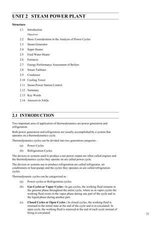
- 26. Power Plant Engineering distance through many boiler passes. The induced draft fan works in conjunction with the forced draft fan allowing the furnace pressure to be maintained slightly below atmospheric. 2.6.5 High Pressure Boilers In all modern power plants, high pressure boilers (> 100 bar) are universally used as they offer the following advantages. In order to obtain efficient operation and high capacity, forced circulation of water through boiler tubes is found helpful. Some special types of boilers operating at super critical pressures and using forced circulations are described in this chapter. (a) The efficiency and the capacity of the plant can be increased as reduced quantity of steam is required for the same power generation if high pressure steam is used. (b) The forced circulation of water through boiler tubes provides freedom in the arrangement of furnace and water walls, in addition to the reduction in the heat exchange area. (c) The tendency of scale formation is reduced due to high velocity of water. (d) The danger of overheating is reduced as all the parts are uniformly heated. (e) The differential expansion is reduced due to uniform temperature and this reduces the possibility of gas and air leakages. (f) Some special types of high pressure supercritical boilers are described in this chapter. 2.6.6 LA MONT Boiler A forced circulation boiler was first introduced in 1925 by La Mont. The arrangement of water circulation and different components are shown in the figure. The feed water from hot well is supplied to a storage and separating drum (boiler) through the economizer. Most of the sensible heat is supplied to the feed water passing through the economizer. A pump circulates the water at a rate 8 to 10 times the mass of steam evaporated. This water is circulated through the evaporator tubes and the part of the vapour is separated in the separator drum. The large quantity of water circulated (10 times that of evaporation) prevents the tubes from being overheated. Chimney Fan Air preheater Air Feed water Feed Economise water r Heater Main steam Hotgas Storage And Evaporator Separator (convective) drum Preheated Down Combustion comer Chamber Fire gate Evaporator Circulating Fuel Ash pan (radiant) Pump Distributing header Figure 2.24 : LA MONT Boiler The centrifugal pump delivers the water to the headers at a pressure of 2.5 bar above the drum pressure. The distribution headers distribute the water through the nozzle into the evaporator. The steam separated in the boiler is further passed through the super-heater. 46
- 27. Secure a uniform flow of feed water through each of the parallel boiler circuits a choke Steam Power Plant is fitted entrance to each circuit. These boilers have been built to generate 45 to 50 tonnes of superheated steam at a pressure of 120 bars and temperature of 500°C. Recently forced circulation has been introduced in large capacity power 2.6.7 Benson Boiler The main difficulty experienced in the La Mont boiler is the formation and attachment of bubbles on the inner surfaces of the heating tubes. The attached bubbles reduce the heat flow and steam generation as it offers higher thermal resistance compared to water film : (a) If the boiler pressure was raised to critical pressure (225 atm), the steam and water would have the same density and therefore the danger of bubble formation can be completely avoided. (b) Natural circulation boilers require expansion joints but these are not required for Benson as the pipes are welded. The erection of Benson boiler is easier and quicker as all the parts are welded at site and workshop job of tube expansion is altogether avoided. (c) The transport of Benson boiler parts is easy as no drums are required and majority of the parts are carried to the site without pre-assembly. (d) The Benson boiler can be erected in a comparatively smaller floor area. The space problem does not control the size of Benson boiler used. (e) The furnace walls of the boiler can be more efficiently protected by using small diameter and close pitched tubes. (f) The superheater in the Benson boiler is an integral part of forced circulation system, therefore no special starting arrangement for superheater is required. (g) The Benson boiler can be started very quickly because of welded joints. (h) The Benson boiler can be operated most economically by varying the temperature and pres- sure at partial loads and overloads. The desired temperature can also be maintained constant at any pressure. (i) Sudden fall of demand creates circulation problems due to bubble formation in the natural circulation boiler which never occurs in Benson boiler. This feature of insensitiveness to load fluctuations makes it more suitable for grid power station as it has better adaptive capacity to meet sudden load fluctuations. (j) The blow-down losses of Benson boiler are hardly 4% of natural circulation boilers of same capacity. (k) Explosion hazards are not at all severe as it consists of only tubes of small diameter and has very little storage capacity compared to drum type boiler. During starting, the water is passed through the economiser, evaporator, superheater and back to the feed line via starting valve. During starting, first circulating pumps are started and then the burners are started to avoid the overheating of evaporator and superheater tubes. 2.6.8 Loeffler Boiler The major difficulty experienced in Benson boiler is the deposition of salt and sediment on the inner surfaces of the water tubes. The deposition reduced the heat transfer and ultimately the generating capacity. This further increased the danger of overheating the tubes due to salt deposition as it has high thermal resistance. The difficulty was solved in Loffler boiler by preventing the flow of water into the boiler tubes. Most of the steam is generated outside from the feed water using part of the superheated steam coming-out from the boiler. 47