2. 38 G.R. Vergara and N.F. Marrouche
This led to the development of electro-anatomical
mapping systems (EAM), in which information regarding
catheter position in a 3D space is combined with electro-
physiological information in real time to provide an accurate
localization of the catheter tip while, at the same time, data
regarding electrophysiological properties of the underlying
myocardial substrate.
Eventually, the mechanisms of more complex arrhyth-
mias, such as atrial fibrillation and scar-based monomorphic
ventricular tachycardia, were slowly being elucidated. This
was followed by more difficult ablation procedures which
required more accurate mapping systems able to provide
real-time information.
The introduction of EAM combined with Cardiac
Computerized Tomography (CCT), cardiac Magnetic
Resonance Imaging (cMRI) and real-time intracardiac
echocardiography (ICE) allows for more precise mapping
with significant improvement in cure rates for ablation pro-
cedures. However, most of these techniques are essentially
x-ray based and expose the patient and the operator to the
noxious effects of ionizing radiation.
2.1 MRI for Arrhythmic Substrate
Evaluation: Tissue Characterization
and Anatomic Considerations
2.1.1 Atrial Fibrillation Ablation
2.1.1.1 Anatomical Considerations
Atrial fibrillation (AF) is the most common sustained cardiac
arrhythmia, affecting more than two million people in the
United States,2
with an incidence rate of 0.4%3
of the general
population. Electrical pulmonary vein isolation (PVI) using
radiofrequency (RF) ablation is effective in symptomatic,
drug-refractory AF. Still, reported success rates of the proce-
dure vary significantly with reported AF recurrences ranging
from 25% to 60%.
Ever since it was first published in 1998 by Haissaguerre
et al., pulmonary vein (PV) triggers have been recognized as
the most common source of paroxysmal atrial fibrillation;
electrical isolation of the PV has remained the cornerstone of
atrial fibrillation ablation.4
Most ablation techniques include,
in one way or the other, a group of lesions distributed in a
circular fashion to electrically isolate the PV so that it
becomes of utmost importance then to clearly define the left
atrial (LA) and PV anatomy prior to any ablation.
PV anatomy is variable in the general population, and this
is more significant in the AF patient population. Kato et al.5
observed up to 38% anatomical variants in patients with AF,
these patients typically had larger PV diameter than controls.
Wazni et al.3
confirmed the presence of a right middle PV in
18–29% of patients undergoing evaluation for AF ablation,
and this structure has been described as a focus for AF
initiation. The importance of a clear understanding of the
patient’s anatomy is of paramount importance when plan-
ning an ablation procedure. cMRI can very clearly demon-
strate the presence, location, and anatomical variants of PV’s
prior to ablation; allowing for procedural planning.
2.1.1.2 Integration Between Left Atrium
cMRI and Non-fluoroscopy Based
Mapping Systems
Integration of LA cMRI images with a non-fluoroscopy-
based mapping system is a crucial step in AF ablation,
since it allows for precise catheter monitoring in a real-time
three-dimensional manner during ablation. Integration typi-
cally consists in fusing two images: CCT or cMRI with an
electro-anatomical map (EAM) or shell of the LA. This pro-
cess usually consists of three steps: (1) image acquisition, (2)
segmentation, and (3) registration. Accuracy of integration
is crucial for safe catheter navigation and positioning; how-
ever, pitfalls related to integration of CCT/cMRI with EAM
systems could occur due to registration errors and changes in
the LA volume, size, and shape between the time of image
acquisition and integration with the EAM system.
2.1.1.3 Tissue Characterization, Staging
of Atrial Fibrillation, and Prediction
of AF Ablation Success
Late gadolinium enhancement-MRI (LGE-MRI) of the LA has
been used as a marker for LA fibrosis and structural remodeling.
Oakes et al.6
have shown that the amount of LGE in the LA is
a powerful predictor of AF ablation outcome. The rate of AF
recurrence post-ablation was directly related to the degree of
LA LGE pre-ablation.6
The amount of LGE of the LA as a
marker of scar formation post-AF ablation has also been directly
correlated with ablation success in a pilot study.7
The use of LGE-MRI pre-ablation for risk stratification
and ablation success prediction has allowed for the develop-
ment of a personalized management approach to atrial fibril-
lation. Upon initial clinical evaluation and after determining
the AF burden, a cardiac MRI was acquired. The following
image acquisition parameters are used.
2.1.1.4 MRI Image Acquisition
Pre-ablation cardiac MRI is obtained either on a 1.5 T Avanto
or on a 3.0 T Veerio scanners (Siemens Medical Solutions,
Erlangen, Germany) using a TIM phased-array receiver coil.
The scan is acquired 15 min after 0.1 mmol/kg Multihance
(Bracco Diagnostic Inc., Princeton, NJ) contrast agent injec-
tion, using a 3D inversion recovery, respiration-navigated,
ECG-gated, and gradient-echo pulse sequence. Typical
acquisition parameters were free-breathing using navigator
gating, a transverse imaging volume with voxel size=1.25 ×
1.25 × 2.5 mm, and GRAPPA with R=2 and 46 reference
3. 392 Magnetic Resonance Imaging: Description of Technology and Protocols
lines. ECG gating is used to acquire a small subset of phase
encoding views during the diastolic phase of the LA cardiac
cycle. The time interval between the R-peak of the ECG and
the start of data acquisition was defined using the cine images
of the LA. Fat saturation is used. The TE of the scan (2.3 ms)
is chosen such that fat and water are out of phase and the
signal intensity of partial volume fat-tissue voxels was
reduced allowing improved delineation of the LA wall
boundary. The T1 value for the LGE-MRI scan is identified
using a scout scan. Typical scan time for the LGE-MRI study
is 5–10 min.
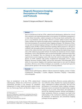
2.1.1.5 LGE-MRI Quantification of Pre-ablation
Fibrosis/Structural Remodeling
and Post Ablation Scarring
After image acquisition, the epicardial and endocardial LA
borders are manually contoured using the CoreView image
display and analysis software. The relative extent of pre-
ablation enhancement and post-ablation scar is then quanti-
fied within the LA wall with a threshold-based algorithm
utilizing pixel intensities from normal based on a bimodal
distribution (Fig. 2.1). Since post-ablation scar pixel inten-
sity is significantly higher than pre-ablation delayed enhance-
ment, a different threshold is used for analysis and imaging
of scar.
2.1.1.6 Staging AF Using MRI
Supported by outcome data we have established at the
University of Utah, a clinical staging system composed of
four stages based on the amount of pre-ablation delayed
enhancement (fibrosis) as a percentage of the volume of the
left atrial wall.8
This clinical staging system includes four
stages: Utah I£5% enhancement, Utah II>5–20%, Utah
III>20–35%, and Utah IV>35%. When performing a
Step 1
Acquire DE-MRI
Step 6
Render enhancement in 3D
Step 5
Detect enhancement of LA wall
Step 4
Analyze MRI pixel intensity
0.012
0.01
0.008
0.006
0.004
0.002
0
0 50 100 150 200
Step 2
Label LA wall
Step 3
Isolate LA wall
Fig. 2.1 LGE-MRI quantification of pre-ablation fibrosis/structural
remodeling and postablation scarring. After LGE-MR images are
obtained (1), the endocardial and epicardial borders are manually
contoured and isolated (2, 3), and the extent of LGE is then quantified
using a pixel intensity distribution (4), qualitative confirmation is then
performed, a color lookup table mask is then applied to differentiate
enhanced and non-enhanced tissue (5), and finally a 3D rendering of the
LA is generated allowing for better visualization and spatial localiza-
tion of the late gadolinium enhancement (6)
4. 40 G.R. Vergara and N.F. Marrouche
multivariate analysis, it was found that the number of PV
isolated in patients with Utah stage II and the total amount
of scar in those with Utah stage III were predictors of suc-
cess. Patients with minimal pre-ablation fibrosis, Utah stage
I, did well regardless of the number of PV isolated or the
total amount of scar, whereas those with advanced atrial
remodeling as assessed by LGE-MRI, Utah stage IV, did
poorly regardless.8
Moreover, in a multivariate regression model, LGE-MRI
evaluation of the left atrial substrate was shown to improve
the predictive value of the CHADS2
score, allowing defin-
ing patients at higher risk of stroke despite having a low or
moderate CHADS2
score.9
Patients with a previous stroke
had a significantly higher percentage of LA fibrosis com-
pared to those without (24.4%±12.4 vs. 16.1%±9.8,
p=<0.001). There was also a significant difference in the
rate of thromboembolism between patients with Utah stage
I and those with stage IV. Also it was found that patients
with higher risk for stroke (CHADS2
score³2) had higher
amounts of LA fibrosis. Using univariate and multivariate
regression analysis, LGE-MRI quantified left atrial struc-
tural remodeling was independently associated with stroke.9
Based on this staging system, a comprehensive cMRI-based
AF management algorithm (Fig. 2.2) has been developed,
which helps in triaging patients to AF ablation, as well as
planning a corresponding ablation strategy and future anti-
coagulation strategy.
2.1.2 Safety
Control of collateral damage is critical during AF ablation.
The LA is anatomically related with several vital structures;
the pulmonary artery runs along the LA dome, the ascending
aorta relates with the LA anterior wall and dome, the
descending aorta with the posterior wall, the phrenic nerve is
anterior to the right pulmonary veins, and the esophagus
runs behind the posterior wall and the left inferior PV.
Understanding of these relationships and monitoring of these
anatomical structures during ablation is of paramount impor-
tance to avoid disastrous complications. LGE of the esopha-
gus has been used to monitor for post-ablation injury.10
In
one report, Badger et al.11
studied 41 patients’ LGE-MRI
pre-AF ablation, 24 h post-AF ablation, and 3 months after
the ablation. Five patients demonstrated esophageal enhance-
ment 24 h post-ablation and esophageal injury confirmed by
esophagogastroduodenoscopy (EGD). EGD and cMRI were
repeated a week later and confirmed resolution of esophageal
LGE and endoscopic resolution of these lesions as well.
Follow-up cMRI at 3 months post ablation demonstrated no
LGE on the esophageal wall (Fig. 2.3).
2.2 Ventricular Tachycardia Ablation
Arrhythmia substrate evaluation is critical for ventricular
tachycardia (VT) evaluation and ablation strategy planning.
cMRI has the capacity to assess not only ventricular systolic
function but also, and simultaneously, to provide insights
into the myocardial underlying pathology.
2.2.1 Scar-Based Monomorphic Ventricular
Tachycardia: Ischemic VT
VT associated with myocardial scars, either ischemic
(Fig. 2.4a–c), due to sarcoidosis, or cardiomyopathy, is
Patients with AF
LGE-MRI to assess degree
of fibrosis (AF staging)
Utah I Utah II Utah III Utah IV
Pulmonary Vein
Isolation
Consider
stop warfarin
Consider
stop warfarin
Continue
warfarin
Continue
warfarin
Pulmonary Vein
Encircling
Posterior
wall/septal
debulking
Rate/Rhythm
Control
Fig. 2.2 University of Utah
proposed LGE-MRI-based
management algorithm for
patients with AF
5. 412 Magnetic Resonance Imaging: Description of Technology and Protocols
typically a monomorphic re-entrant arrhythmia dependent
upon the presence of a conduction isthmus. This isthmus
could be inside the scar, around the scar, or around a fixed
anatomical structure (i.e., cardiac valves). These arrhyth-
mias are usually not well tolerated hemodynamically.
Different strategies for the mapping of these VTs include
scar/substrate assessment with electro-anatomical mapping
system, pace mapping, and evaluation of diastolic potentials.
These different strategies, however, are time consuming,
adding length and risk to these procedures.
Fig. 2.3 LGE-MRI of the esophagus and EGD. (a) LGE-MRI demon-
strates enhancement of the anterior esophageal wall (arrows) which
correlates with a lesion (green arrow) found on EGD (c). (b) A week
later, there has been resolution of late gadolinium enhancement on MRI
(arrows) and resolution of the lesion on EGD (d and e)
Fig. 2.4 Characteristic cMRI of patients with ischemic scar. Cardiac
LGE-MRI (late gadolinium enhancement phase sensitive inversion
recovery (PSIR) sequence) of patient with ischemic cardiomyopathy and
scar-based monomorphic ventricular tachycardia (a: short axis view, b:
two chamber view, and c: long axis view) demonstrating a scar (green
arrowheads) in the distal antero-septal segments of the LV (bright area)
6. 42 G.R. Vergara and N.F. Marrouche
LGE-MRI provides a reliable assessment of myocardial
scar, particularly in ischemic substrates. Bello et al. found,
in 18 patients, a correlation between infarct surface area and
infarct mass as defined by LGE-MRI and VT inducibility
on EPS.12
On another larger study, Schmidt et al. demon-
strated the association between “scar border zone,” a dis-
tinct zone than dense scar based on pixel intensity on
LGE-MRI, and inducibility in EPS.13
In this study, the
amount of scar border zone was a good predictor of induc-
ibility, whereas the total amount of dense scar was not.
Information about VT substrate has been used, albeit
experimentally, to predict the VT circuit. Ashikaga et al.
correlated, in an animal model, surface ventricular mapping
with ex-vivo high-resolution cMRI and found correlation
between exit sites and conduction isthmus with isles of via-
ble myocardium within the scar.14
2.2.2 Arrhythmogenic Right Ventricular
Dysplasia/Cardiomyopathy
Arrhythmogenic right ventricular dysplasia/cardiomyopa-
thy (ARVD/C) is cardiomyopathy which affects mainly the
right ventricle (RV). It is characterized by fatty/fibro-fatty
replacement and myocyte loss, ventricular aneurysms, ven-
tricular arrhythmias, and right ventricular failure. There is
mounting evidence that the underlying etiology of ARVD/C
is desmosomal dysfunction.15
Its prevalence is estimated to
be around 1:5,000 in the United States, and accounts for 5%
of all sudden cardiac death in patients younger than 35 years
old in the United States. Its diagnosis is based on a set of
major and minor criteria established by the Task Force of
Cardiomyopathy.16
They include evaluation for structural
and electrophysiological abnormalities, as well as elements
from the patient history.
Cardiac MRI is a very useful noninvasive tool for the
evaluation of ARVD/C since it can define the presence of
myocardial fat infiltration, observed in T1-weighted
sequences,15
and it can also allow for evaluation of the struc-
ture of the RV and quantification of its function.
2.2.3 Ventricular Tachycardia in Structurally
Normal Ventricles (Idiopathic Ventricular
Tachycardia)
Approximately 10% of all ventricular tachycardias occur in
ventricles that are structurally normal.17
The presence of sub-
clinical structural abnormalities is not always evident in the
echocardiogram and/or coronary angiogram which are usu-
ally normal. MRI in these cases may assist in the differential
diagnosis and point toward a different etiology.
2.3 Radiofrequency Ablation Lesion
Characterization
Characterization of the myocardial changes following
RFablationisofimportancesinceitwouldallowforvalidation
of therapy delivered and ultimately for ablation endpoints.
2.3.1 Acute Wall Edema Post Ablation
Acute edema, enhancement on T2w images performed
immediately after AF ablation, correlates significantly with
low voltage areas (defined as<0.05 mV) mapped using the
CARTO system. However, the area enhanced with T2w
imaging is much larger than the area covered by LGE on
MRI acutely post-AF ablation.18
Acute post-ablation edema
is seen not only in regions directly subjected to RF energy
but also in distant regions (Fig. 2.5) and it does not predict
final scar formation defined by LGE-MRI at 3 months.18
A
LGE-MRI at 3 months after AF ablation shows loss of
enhancement on T2w images consistent with edema reso-
lution in areas free of scar. Edema seen acutely in regions
other than in ablated areas suggests a mechanism other than
direct radiofrequency thermal lesion as its cause.
Finally, the presence of edema in regions away from areas
that result in scar formation, as well as its association with
low voltage on electro-anatomical mapping may explain, at
least partially, the presence of acute PV disconnection, and
late reconnection with edema resolution, or ventricular myo-
cardial recovery following VT ablation.18
2.3.2 Late Gadolinium-Enhanced Defined
Scar and Non-reflow Phenomenon
Heterogeneity in the LA wall is seen on acute post-ablation
LGE-MRI scans with portions showing very little or no
enhancement at all even in areas that received direct RF
energy (Fig. 2.6). In a porcine model of ablation, these areas
correlated well with lesion formation, particularly with areas
with the highest amount of injury. Within minutes there is
resolution of these areas of non-enhancement and they mani-
fest all the features of ablated/scarred areas. These areas of
no-enhancement are believed to correspond to areas of no-
reflow, phenomenon similar to that seen in ventricles in the
immediate post-MI period.18
2.3.3 Late Imaging and Recurrences
The amount of scar and the number of circumferentially
scarred PVA on LGE-MRI is associated with better outcomes
7. 432 Magnetic Resonance Imaging: Description of Technology and Protocols
for AF ablation, confirming earlier studies that total LA abla-
tion scar burden is associated with AF termination.19
However, complete PVA isolation is difficult to achieve and
complicated by the fact that certain changes seen acutely are
reversible over a 3-month period.
Acutely post-ablation voltage and LGE-MRI defined
scar do not have a good correlation. However, acute
LGE-MRI areas correlate well with areas of low voltage
at 3 months. These areas of acute LGE-MRI likely rep-
resent areas with irreversible damage from RF ablation
whereas the larger area of low voltage during the acute
post-ablation period likely represents a combination of tis-
sue edema, other reversible changes, and areas that will
scar completely.
LGE-MRI can also accurately identify the location of
breaks in ablation lesion sets, and its correlation with con-
duction recovery, which may explain post-ablation AF recur-
rences.19
Badger et al.20
demonstrated that AF recurrences
following ablation are associated with significant gaps
between lesions, and that these gaps correlated well with
recovery of local EGMs or PV electrical conduction. This
has allowed to better plan and tailor re-do procedures for
patients with PV tachycardias, atrial/flutters, or atrial
fibrillation.
2.4 The Future: Real-Time-MRI
The assessment of lesion formation during electrophysio-
logic procedures has always been a challenge; cMRI allows
for visualization of location and extent of RF ablation lesion,
scar formation in the myocardium, and potentially real-time
assessment of lesion formation. Real-time MRI (RT-MRI)–
based imaging and ablation system has the potential advan-
tage of tissue lesion visualization during RF delivery, which
could be used as an ablation end point. Electrophysiology
RT-MRI-guided procedures have been carried out by a few
laboratories.
Fig. 2.5 Post-ablation edema extends beyond ablated regions. Cardiac
MRI from six patients post-AF ablation demonstrates edema (bright
T2w signal) extending not only in regions where RF energy was
delivered (posterior wall and PV antrum) but also remote LA regions
(anterior wall/dome and lateral wall)
8. 44 G.R. Vergara and N.F. Marrouche
MRI-guided ablation in the atrium has recently been
reported by Schmidt et al.21
and by Hoffmann et al.22
In one
ofthesestudies,MRIangiographyoftheatriumwasacquired,
the atrium surface was segmented, and real-time catheter
navigation was then carried out using this 3D reconstruction;
however, no images were acquired during ablation21
; rather,
immediately postablation lesion formation was confirmed by
LGE imaging. In the other study,22
the catheters were navi-
gated using RT-MRI sequences; however, there was no
immediate tissue visualization during RF delivery and lesion
formation, although there was T2w evaluation of the abla-
tion site just before and after the ablation of the cavo-tricus-
pid isthmus. These two studies were done in 1.5-T MRI.
At our EP-MRI suite, we could demonstrate the feasibil-
ity to safely navigate and pace and record intracardiac EGMs
in the atrial chambers under 3-T real-time MRI guidance.23
We used a novel 3-T real-time (RT) MRI–based porcine
RF ablation model with visualization of lesion formation in
the atrium during RF energy delivery (Fig. 2.7).
In this model, RF energy was delivered under cMRI
visualization at 3-T using custom RT-MRI software. A
novel MRI-compatible mapping and ablation catheter was
also used. Under RT-MRI, this catheter was guided and
positioned within either the left or right atrium. Unipolar
and bipolar electrograms were recorded. The catheter tip-
tissue interface was then visualized with a T1w FLASH
(T1-weighted fast low angle shot) sequence. RF energy was
then delivered in a power-controlled fashion, and myocar-
dial changes and lesion formation were visualized with a
T2w HASTE (half Fourier with single shot turbo spin echo)
sequence during the ablation. The presence of a lesion
was confirmed by LGE- MRI and macroscopic tissue
examination.
According to these studies, MRI-compatible catheters can
be navigated and RF energy safely delivered under 1.5- and
3-T RT-MRI guidance. It was also feasible to record EGMs
in the atrium and ventricle during real-time image acquisi-
tion. Real-time visualization of lesion as it forms during
Fig. 2.6 Non-reflow
phenomenon on LGE-MRI.
(a1, a2) Cardiac LGE-MRI of
two patients immediately
following AF ablation
demonstrates areas of LGE
mixed with areas of no
enhancement in the posterior
wall (blue arrowheads). These
same patients underwent
LGE-MRI at 3 months post
ablation. (b1,b2)The above areas
correlated well with scar
formation in the posterior wall
(blue arrows)
9. 452 Magnetic Resonance Imaging: Description of Technology and Protocols
delivery of RF energy was possible and demonstrated using
T2-w HASTE imaging under 3-T.
Finally, catheter visualization and myocardial tissue
imaging under RT-MRI during RF energy could help improve
ablation procedure outcomes by immediate assessment of
ablation endpoints in the myocardium.
References
1. Mitsui T, Ijima H, Okamura K, Hori M. Transvenous electrocautery
of the atrioventricular connection guided by the His electrogram.
Jpn Circ J. 1978;42(3):313-318.
2. Feinberg WM, Blackshear JL, Laupacis A, Kronmal R, Hart RG.
Prevalence, age distribution, and gender of patients with atrial fibril-
lation. Analysis and implications. Arch Intern Med. 1995;155:
469-473.
3. Wazni OM, Tsao HM, Chen SA, et al. Cardiovascular imaging in the
management of atrial fibrillation. J Am Coll Cardiol. 2006;48(10):
2077-2084. Epub 2006 Nov 1.
4. Haïssaguerre M, Jaïs P, Shah DC, et al. Spontaneous initiation of
atrial fibrillation by ectopic beats originating in the pulmonary veins.
N Engl J Med. 1998;339(10):659-666.
5. Kato R, Lickfett L, Meininger G, et al. Pulmonary vein anatomy in
patients undergoing catheter ablation of atrial fibrillation: lessons
learned by use of magnetic resonance imaging. Circulation. 2003;
107(15):2004-2010.
6. Oakes RS, Badger TJ, Kholmovski EG, et al. Detection and
quantification of left atrial structural remodeling with delayed-
enhancement magnetic resonance imaging in patients with atrial
fibrillation. Circulation. 2009;119(13):1758-1767.
7. Peters DC, Wylie JV, Hauser TH, et al. Recurrence of atrial fibrilla-
tion correlates with the extent of post-procedural late gadolinium
enhancement: a pilot study. JACC Cardiovasc Imaging. 2009;2(3):
308-316.
8. Akoum N, Daccarett M, McGann C, et al. Atrial fibrosis helps
select the appropriate patient and strategy in catheter ablation of
atrial fibrillation: a DE-MRI guided approach. J Cardiovasc
Electrophysiol. 2011;22(1):16-22.
9. Daccarett M, Badger TJ, Akoum N, et al. Association of left atrial
fibrosis detected by delayed-enhancement magnetic resonance
imaging and the risk of stroke in patients with atrial fibrillation. J Am
Coll Cardiol. 2011;57(7):831-838.
10. Meng J, Peters DC, Hsing JM, et al. Late gadolinium enhancement
of the esophagus is common on cardiac MR several months after
pulmonary vein isolation: preliminary observations. Pacing Clin
Electrophysiol. 2010;33(6):661-666.
11. Badger TJ, Adjei-Poku YA, Burgon NS, et al. Initial experience of
assessing esophageal tissue injury and recovery using delayed-
enhancement MRI after atrial fibrillation ablation. Circ Arrhythm
Electrophysiol. 2009;2(6):620-625.
12. Bello D, Fieno DS, Kim RJ, et al. Infarct morphology identifies
patients with substrate for sustained ventricular tachycardia. J Am
Coll Cardiol. 2005;45(7):1104-1108.
13. Schmidt A, Azevedo CF, Cheng A, et al. Infarct tissue heterogene-
ity by magnetic resonance imaging identifies enhanced cardiac
arrhythmia susceptibility in patients with left ventricular
dysfunction. Circulation. 2007;115(15):2006-2014.
Fig. 2.7 Real-time MRI ablation and lesion visualization at 3-T.
(a and b) MRI-compatible RF catheter guided under RT-MRI from the
IVC into RA, the signal from the tracking elements is displayed and
color coded (red: distal and yellow: proximal) to allow the operator
catheter visualization. (c–g) Real-time 20 W power lesion can be
seen (T2w HASTE) as it is being formed from catheter touch down
(c) to 45 (g) (green arrows)
10. 46 G.R. Vergara and N.F. Marrouche
14. Ashikaga H, Sasano T, Dong J, et al. Magnetic resonance-based
anatomical analysis of scar-related ventricular tachycardia: impli-
cations for catheter ablation. Circ Res. 2007;101(9):939-947.
15. Jain A, Tandri H, Calkins H, Bluemke DA. Role of cardiovascular
magnetic resonance imaging in arrhythmogenic right ventricular
dysplasia. J Cardiovasc Magn Reson. 2008;10(1):32.
16. McKenna WJ, Thiene G, Nava A, et al. Diagnosis of arrhyth-
mogenic right ventricular dysplasia/cardiomyopathy. Task Force of
the Working Group Myocardial and Pericardial Disease of the
European Society of Cardiology and of the Scientific Council on
Cardiomyopathies of the International Society and Federation of
Cardiology. Br Heart J. 1994;71(3):215-218.
17. Klein LS, Shih HT, Hackett FK, Zipes DP, Miles WM.
Radiofrequency catheter ablation of ventricular tachycardia in
patients without structural heart disease. Circulation. 1992;85(5):
1666-1674.
18. Vergara GR, Marrouche NF. Tailored management of atrial fibrilla-
tion using a LGE-MRI based model: from the clinic to the electro-
physiology laboratory. J Cardiovasc Electrophysiol. 2011;22(4):
481-487.
19. McGann CJ, Kholmovski EG, Oakes RS, et al. New magnetic
resonance imaging-based method for defining the extent of left
atrial wall injury after the ablation of atrial fibrillation. J Am Coll
Cardiol. 2008;52(15):1263-1271.
20. Badger TJ, Daccarett M, Akoum NW, et al. Evaluation of left atrial
lesions after initial and repeat atrial fibrillation ablation: lessons
learned from delayed-enhancement MRI in repeat ablation proce-
dures. Circ Arrhythm Electrophysiol. 2010;3(3):249-259.
21. Schmidt EJ, Mallozzi RP, Thiagalingam A, et al. Electroanatomic
mapping and radiofrequency ablation of porcine left atria and atrio-
ventricular nodes using magnetic resonance catheter tracking. Circ
Arrhythm Electrophysiol. 2009;2(6):695-704.
22. Hoffmann BA, Koops A, Rostock T, et al. Interactive real-time
mapping and catheter ablation of the cavotricuspid isthmus guided
by magnetic resonance imaging in a porcine model. Eur Heart J.
2010;31(4):450-456. Epub 2009 Nov 5.
23. Vergara GR, Vijayakumar S, Kholmovski EG, et al. Real time MRI
guided radiofrequency atrial ablation and visualization of lesion
formation at 3-Tesla. Heart Rhythm. 2011;8(2):295-303.