SlideShare une entreprise Scribd logo
1  sur  4
ARM architecture

The ARM architecture describes a family of RISC-based computer processors designed
and licensed by British company ARM Holdings. It was first developed in the 1980s.
ARM Holdings itself does not manufacture its own electronic chips, but licenses its
designs to other semiconductor manufacturers. Using a RISC based approach to
computer design, ARM processors require significantly fewer transistors than
processors that would typically be found in a traditional computer. The benefits of this
approach are lower costs, less heat, and less power usage, traits that are desirable for
use in light, portable, battery-powered devices such as smart phones and tablet
computers. The reduced complexity and simpler design allows companies to build a
low-energy system      on   a   chip for    an embedded   system incorporating   memory,
interfaces, radios, etc.

In the C programming language, the loop is:
     while (i != j) {
        if (i > j)
             i -= j;
        else
             j -= i;
     }

In ARM assembly, the loop is:


loop:      CMP     Ri, Rj                  ; set condition "NE" if (i != j),
                                           ;               "GT" if (i > j),
                                           ;            or "LT" if (i < j)
           SUBGT Ri, Ri, Rj                ; if "GT" (greater than), i = i-j;
           SUBLT Rj, Rj, Ri                ; if "LT" (less than), j = j-i;
           BNE loop
FEATURES

• 32-bit ARM7TDMI-S microcontroller.
• 32 kB of on-chip static RAM and 512 kB of on-chip Flash program memory. 128 bit
wide interface/accelerator enables high speed 60 MHz operation.
• Single Flash sector or full chip erase in 400ms and programming of 256 bytes in 1 ms.
• One (LPC2131/2132) or two (LPC2138) 8 channel 10-bit A/D converters provide a
total of up to 16 analog inputs, with conversion times as low as 2.44 s per channel.
• Single 10-bit D/A converter provides variable analog output.
• Two 32-bit timers/counters (with four capture and four compare channels each), PWM
unit (six outputs) and watchdog.
• Real-time clock equipped with independent power and clock supply permitting
extremely low power consumption in powersave modes.
• Multiple serial interfaces including two UARTs (16C550), two Fast I2C (400 kbit/s),
SPI™ and SSP with buffering and variable data length capabilities.
• Vectored interrupt controller with configurable priorities and vector addresses.
• Up to 47 of 5 V tolerant general purpose I/O pins.
• Up to nine edge or level sensitive external interrupt pins available.
• 60 MHz maximum CPU clock available from programmable on-chip Phase-Locked
Loop (PLL) with settling time of 100microseconds.
• On-chip crystal oscillator with an operating range of 1 MHz to 30 MHz.
• Power saving modes include Idle and Power-down.
• Individual enable/disable of peripheral functions as well as peripheral clock scaling
down for additional power optimization.
• Processor wake-up from Power-down mode via external interrupt.
• Single power supply chip with Power-On Reset (POR) and Brown-Out Detection
(BOD) circuits:
- CPU operating voltage range of 3.0 V to 3.6 V (3.3 V 10 %) with 5 V tolerant I/O pads.
Device         No. of Pins    On-Chip        On-chip        No. of 10-     No. of 10-
                              RAM            FLASH          bit     AD     bit     DA
                                                            Channels       Channels
LPC2138        64             32K            512K           2x8            1


ARM7TDMI-S PROCESSOR

The ARM7TDMI-S is a general purpose 32-bit microprocessor, which offers high
performance and very low power consumption. The ARM architecture is based on
Reduced Instruction Set Computer (RISC) principles, and the instruction set and related
decode mechanism are much simpler than those of microprogrammed Complex
Instruction Set Computers. This simplicity results in a high instruction throughput and
impressive real-time interrupt response from a small and cost-effective processor core.
Pipeline techniques are employed so that all parts of the processing and memory
systems can operate continuously. Typically, while one instruction is being executed, its
successor is being decoded, and a third instruction is being fetched from memory. The
ARM7TDMI-S processor also employs a unique architectural strategy known as
THUMB, which makes it ideally suited to high-volume applications with memory
restrictions, or applications where code density is an issue. The key idea behind
THUMB is that of a super-reduced instruction set. Essentially, the ARM7TDMI-S
processor has two instruction sets:


• The standard 32-bit ARM instruction set.
• A 16-bit THUMB instruction set.


The THUMB set’s 16-bit instruction length allows it to approach twice the density of
standard ARM code while retaining most of the ARM’s performance advantage over a
traditional 16-bit processor using 16-bit registers. This is possible because THUMB
code operates on the same 32-bit register set as ARM code.
THUMB
To improve compiled code-density, processors since the ARM7TDMI (released in 1994)
have featured Thumb instruction set, which have their own state. (The "T" in "TDMI"
indicates the Thumb feature.) When in this state, the processor executes the Thumb
instruction set, a compact 16-bit encoding for a subset of the ARM instruction set. Most
of the Thumb instructions are directly mapped to normal ARM instructions. The space-
saving comes from making some of the instruction operands implicit and limiting the
number of possibilities compared to the ARM instructions executed in the ARM
instruction set state.
In Thumb, the 16-bit opcodes have less functionality. For example, only branches can
be conditional, and many opcodes are restricted to accessing only half of all of the
CPU's general purpose registers. The shorter opcodes give improved code density
overall, even though some operations require extra instructions. In situations where the
memory port or bus width is constrained to less than 32 bits, the shorter Thumb
opcodes allow increased performance compared with 32-bit ARM code, as less
program code may need to be loaded into the processor over the constrained memory
bandwidth.


Duty cycle
A duty cycle is the percent of time that an entity spends in an active state as a fraction of the total time
under consideration. The term is often used pertaining to electrical devices, e.g., switching power
supplies. It is also sometimes used pertaining to living systems such as the firing of action
potentials by neurons. In an electrical device, a 60% duty cycle means the power is on 60% of the time
and off 40% of the time. The "on time" for a 60% duty cycle could be a fraction of a second – or for say,
irrigation pumps, days – depending on how long the device's period is. Here one period is the length of
time it takes for the device to go through a complete on/off cycle.

Contenu connexe

Tendances

Arm cortex (lpc 2148) based motor speed
Arm cortex (lpc 2148) based motor speedArm cortex (lpc 2148) based motor speed
Arm cortex (lpc 2148) based motor speedUday Wankar
 
ARM7-ARCHITECTURE
ARM7-ARCHITECTURE ARM7-ARCHITECTURE
ARM7-ARCHITECTURE Dr.YNM
 
Study on 32-bit Cortex - M3 Powered MCU: STM32F101
Study on 32-bit Cortex - M3 Powered MCU: STM32F101Study on 32-bit Cortex - M3 Powered MCU: STM32F101
Study on 32-bit Cortex - M3 Powered MCU: STM32F101Premier Farnell
 
Arm architecture overview
Arm architecture overviewArm architecture overview
Arm architecture overviewSunil Thorat
 
02 : ARM Cortex M4 Specs || IEEE SSCS AlexSC
02 : ARM Cortex M4 Specs || IEEE SSCS AlexSC 02 : ARM Cortex M4 Specs || IEEE SSCS AlexSC
02 : ARM Cortex M4 Specs || IEEE SSCS AlexSC IEEE SSCS AlexSC
 
1: Interfacing using ARM Cortex M4 || IEEE SSCS AlexSC
1: Interfacing using ARM Cortex M4 || IEEE SSCS AlexSC 1: Interfacing using ARM Cortex M4 || IEEE SSCS AlexSC
1: Interfacing using ARM Cortex M4 || IEEE SSCS AlexSC IEEE SSCS AlexSC
 
Introduction to arm architecture
Introduction to arm architectureIntroduction to arm architecture
Introduction to arm architectureZakaria Gomaa
 
LPC 2148 ARM MICROCONTROLLER
LPC 2148 ARM MICROCONTROLLERLPC 2148 ARM MICROCONTROLLER
LPC 2148 ARM MICROCONTROLLERsravannunna24
 
Arm cortex-m4 programmer model
Arm cortex-m4 programmer modelArm cortex-m4 programmer model
Arm cortex-m4 programmer modelMohammed Gomaa
 

Tendances (20)

Arm processor
Arm processorArm processor
Arm processor
 
Arm cortex (lpc 2148) based motor speed
Arm cortex (lpc 2148) based motor speedArm cortex (lpc 2148) based motor speed
Arm cortex (lpc 2148) based motor speed
 
ARM7-ARCHITECTURE
ARM7-ARCHITECTURE ARM7-ARCHITECTURE
ARM7-ARCHITECTURE
 
Arm arc-2016
Arm arc-2016Arm arc-2016
Arm arc-2016
 
Ppt
PptPpt
Ppt
 
ARM CORTEX M3 PPT
ARM CORTEX M3 PPTARM CORTEX M3 PPT
ARM CORTEX M3 PPT
 
ARM Processors
ARM ProcessorsARM Processors
ARM Processors
 
ARM Architecture
ARM ArchitectureARM Architecture
ARM Architecture
 
OMAP
OMAPOMAP
OMAP
 
Study on 32-bit Cortex - M3 Powered MCU: STM32F101
Study on 32-bit Cortex - M3 Powered MCU: STM32F101Study on 32-bit Cortex - M3 Powered MCU: STM32F101
Study on 32-bit Cortex - M3 Powered MCU: STM32F101
 
Arm architecture overview
Arm architecture overviewArm architecture overview
Arm architecture overview
 
02 : ARM Cortex M4 Specs || IEEE SSCS AlexSC
02 : ARM Cortex M4 Specs || IEEE SSCS AlexSC 02 : ARM Cortex M4 Specs || IEEE SSCS AlexSC
02 : ARM Cortex M4 Specs || IEEE SSCS AlexSC
 
1: Interfacing using ARM Cortex M4 || IEEE SSCS AlexSC
1: Interfacing using ARM Cortex M4 || IEEE SSCS AlexSC 1: Interfacing using ARM Cortex M4 || IEEE SSCS AlexSC
1: Interfacing using ARM Cortex M4 || IEEE SSCS AlexSC
 
Lpc1768
Lpc1768Lpc1768
Lpc1768
 
Arm
ArmArm
Arm
 
Introduction to arm architecture
Introduction to arm architectureIntroduction to arm architecture
Introduction to arm architecture
 
Unit vi (2)
Unit vi (2)Unit vi (2)
Unit vi (2)
 
LPC 2148 ARM MICROCONTROLLER
LPC 2148 ARM MICROCONTROLLERLPC 2148 ARM MICROCONTROLLER
LPC 2148 ARM MICROCONTROLLER
 
ARM Architecture
ARM ArchitectureARM Architecture
ARM Architecture
 
Arm cortex-m4 programmer model
Arm cortex-m4 programmer modelArm cortex-m4 programmer model
Arm cortex-m4 programmer model
 

Similaire à Digital electronics

arm 7 microprocessor architecture ans pin diagram.ppt
arm 7 microprocessor architecture ans pin diagram.pptarm 7 microprocessor architecture ans pin diagram.ppt
arm 7 microprocessor architecture ans pin diagram.pptmanikandan970975
 
Unit 4 _ ARM Processors .pptx
Unit 4 _ ARM Processors .pptxUnit 4 _ ARM Processors .pptx
Unit 4 _ ARM Processors .pptxVijayKumar201823
 
Arm corrected ppt
Arm corrected pptArm corrected ppt
Arm corrected pptanish jagan
 
Architecture and Implementation of the ARM Cortex-A8 Microprocessor
Architecture and Implementation of the ARM Cortex-A8 MicroprocessorArchitecture and Implementation of the ARM Cortex-A8 Microprocessor
Architecture and Implementation of the ARM Cortex-A8 MicroprocessorAneesh Raveendran
 
Explain briefly about the major enhancements in ARM processor archite.pdf
Explain briefly about the major enhancements in ARM processor archite.pdfExplain briefly about the major enhancements in ARM processor archite.pdf
Explain briefly about the major enhancements in ARM processor archite.pdfarjunenterprises1978
 
embedded system and microcontroller
 embedded system and microcontroller embedded system and microcontroller
embedded system and microcontrollerSHILPA Sillobhargav
 
Arm usr m,anl
Arm usr m,anlArm usr m,anl
Arm usr m,anlsam570
 
ARM Processor ppt.pptx
ARM Processor ppt.pptxARM Processor ppt.pptx
ARM Processor ppt.pptxjayesh205437
 
Smart operating of home lightning with zigbee communications
Smart operating of home lightning with zigbee communicationsSmart operating of home lightning with zigbee communications
Smart operating of home lightning with zigbee communicationsrajyasri
 
underground cable fault location using aruino,gsm&gps
underground cable fault location using aruino,gsm&gps underground cable fault location using aruino,gsm&gps
underground cable fault location using aruino,gsm&gps Mohd Sohail
 
An Overview of LPC2101/02/03
An Overview of LPC2101/02/03An Overview of LPC2101/02/03
An Overview of LPC2101/02/03Premier Farnell
 
Lpc1769 68 67_66_65_64
Lpc1769 68 67_66_65_64Lpc1769 68 67_66_65_64
Lpc1769 68 67_66_65_64trowftd
 
Unitii armarchitecture-130305014346-phpapp01
Unitii armarchitecture-130305014346-phpapp01Unitii armarchitecture-130305014346-phpapp01
Unitii armarchitecture-130305014346-phpapp01mannepalli Srinivasulu
 

Similaire à Digital electronics (20)

Unit ii arm7 thumb
Unit ii arm7 thumbUnit ii arm7 thumb
Unit ii arm7 thumb
 
Review Multicore processing based on ARM architecture
Review Multicore processing based on ARM architectureReview Multicore processing based on ARM architecture
Review Multicore processing based on ARM architecture
 
arm 7 microprocessor architecture ans pin diagram.ppt
arm 7 microprocessor architecture ans pin diagram.pptarm 7 microprocessor architecture ans pin diagram.ppt
arm 7 microprocessor architecture ans pin diagram.ppt
 
Unit 4 _ ARM Processors .pptx
Unit 4 _ ARM Processors .pptxUnit 4 _ ARM Processors .pptx
Unit 4 _ ARM Processors .pptx
 
Arm corrected ppt
Arm corrected pptArm corrected ppt
Arm corrected ppt
 
Ec8791 arm 9 processor
Ec8791 arm 9 processorEc8791 arm 9 processor
Ec8791 arm 9 processor
 
Architecture and Implementation of the ARM Cortex-A8 Microprocessor
Architecture and Implementation of the ARM Cortex-A8 MicroprocessorArchitecture and Implementation of the ARM Cortex-A8 Microprocessor
Architecture and Implementation of the ARM Cortex-A8 Microprocessor
 
3.TechieNest microcontrollers
3.TechieNest  microcontrollers3.TechieNest  microcontrollers
3.TechieNest microcontrollers
 
Explain briefly about the major enhancements in ARM processor archite.pdf
Explain briefly about the major enhancements in ARM processor archite.pdfExplain briefly about the major enhancements in ARM processor archite.pdf
Explain briefly about the major enhancements in ARM processor archite.pdf
 
embedded system and microcontroller
 embedded system and microcontroller embedded system and microcontroller
embedded system and microcontroller
 
Arm usr m,anl
Arm usr m,anlArm usr m,anl
Arm usr m,anl
 
ARM Processor ppt.pptx
ARM Processor ppt.pptxARM Processor ppt.pptx
ARM Processor ppt.pptx
 
Archi arm2
Archi arm2Archi arm2
Archi arm2
 
Smart operating of home lightning with zigbee communications
Smart operating of home lightning with zigbee communicationsSmart operating of home lightning with zigbee communications
Smart operating of home lightning with zigbee communications
 
Module-2 Instruction Set Cpus.pdf
Module-2 Instruction Set Cpus.pdfModule-2 Instruction Set Cpus.pdf
Module-2 Instruction Set Cpus.pdf
 
underground cable fault location using aruino,gsm&gps
underground cable fault location using aruino,gsm&gps underground cable fault location using aruino,gsm&gps
underground cable fault location using aruino,gsm&gps
 
An Overview of LPC2101/02/03
An Overview of LPC2101/02/03An Overview of LPC2101/02/03
An Overview of LPC2101/02/03
 
Lpc1769 68 67_66_65_64
Lpc1769 68 67_66_65_64Lpc1769 68 67_66_65_64
Lpc1769 68 67_66_65_64
 
Unitii armarchitecture-130305014346-phpapp01
Unitii armarchitecture-130305014346-phpapp01Unitii armarchitecture-130305014346-phpapp01
Unitii armarchitecture-130305014346-phpapp01
 
Arm
ArmArm
Arm
 

Digital electronics

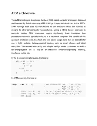
  • 1. ARM architecture The ARM architecture describes a family of RISC-based computer processors designed and licensed by British company ARM Holdings. It was first developed in the 1980s. ARM Holdings itself does not manufacture its own electronic chips, but licenses its designs to other semiconductor manufacturers. Using a RISC based approach to computer design, ARM processors require significantly fewer transistors than processors that would typically be found in a traditional computer. The benefits of this approach are lower costs, less heat, and less power usage, traits that are desirable for use in light, portable, battery-powered devices such as smart phones and tablet computers. The reduced complexity and simpler design allows companies to build a low-energy system on a chip for an embedded system incorporating memory, interfaces, radios, etc. In the C programming language, the loop is: while (i != j) { if (i > j) i -= j; else j -= i; } In ARM assembly, the loop is: loop: CMP Ri, Rj ; set condition "NE" if (i != j), ; "GT" if (i > j), ; or "LT" if (i < j) SUBGT Ri, Ri, Rj ; if "GT" (greater than), i = i-j; SUBLT Rj, Rj, Ri ; if "LT" (less than), j = j-i; BNE loop
  • 2. FEATURES • 32-bit ARM7TDMI-S microcontroller. • 32 kB of on-chip static RAM and 512 kB of on-chip Flash program memory. 128 bit wide interface/accelerator enables high speed 60 MHz operation. • Single Flash sector or full chip erase in 400ms and programming of 256 bytes in 1 ms. • One (LPC2131/2132) or two (LPC2138) 8 channel 10-bit A/D converters provide a total of up to 16 analog inputs, with conversion times as low as 2.44 s per channel. • Single 10-bit D/A converter provides variable analog output. • Two 32-bit timers/counters (with four capture and four compare channels each), PWM unit (six outputs) and watchdog. • Real-time clock equipped with independent power and clock supply permitting extremely low power consumption in powersave modes. • Multiple serial interfaces including two UARTs (16C550), two Fast I2C (400 kbit/s), SPI™ and SSP with buffering and variable data length capabilities. • Vectored interrupt controller with configurable priorities and vector addresses. • Up to 47 of 5 V tolerant general purpose I/O pins. • Up to nine edge or level sensitive external interrupt pins available. • 60 MHz maximum CPU clock available from programmable on-chip Phase-Locked Loop (PLL) with settling time of 100microseconds. • On-chip crystal oscillator with an operating range of 1 MHz to 30 MHz. • Power saving modes include Idle and Power-down. • Individual enable/disable of peripheral functions as well as peripheral clock scaling down for additional power optimization. • Processor wake-up from Power-down mode via external interrupt. • Single power supply chip with Power-On Reset (POR) and Brown-Out Detection (BOD) circuits: - CPU operating voltage range of 3.0 V to 3.6 V (3.3 V 10 %) with 5 V tolerant I/O pads.
  • 3. Device No. of Pins On-Chip On-chip No. of 10- No. of 10- RAM FLASH bit AD bit DA Channels Channels LPC2138 64 32K 512K 2x8 1 ARM7TDMI-S PROCESSOR The ARM7TDMI-S is a general purpose 32-bit microprocessor, which offers high performance and very low power consumption. The ARM architecture is based on Reduced Instruction Set Computer (RISC) principles, and the instruction set and related decode mechanism are much simpler than those of microprogrammed Complex Instruction Set Computers. This simplicity results in a high instruction throughput and impressive real-time interrupt response from a small and cost-effective processor core. Pipeline techniques are employed so that all parts of the processing and memory systems can operate continuously. Typically, while one instruction is being executed, its successor is being decoded, and a third instruction is being fetched from memory. The ARM7TDMI-S processor also employs a unique architectural strategy known as THUMB, which makes it ideally suited to high-volume applications with memory restrictions, or applications where code density is an issue. The key idea behind THUMB is that of a super-reduced instruction set. Essentially, the ARM7TDMI-S processor has two instruction sets: • The standard 32-bit ARM instruction set. • A 16-bit THUMB instruction set. The THUMB set’s 16-bit instruction length allows it to approach twice the density of standard ARM code while retaining most of the ARM’s performance advantage over a traditional 16-bit processor using 16-bit registers. This is possible because THUMB code operates on the same 32-bit register set as ARM code.
  • 4. THUMB To improve compiled code-density, processors since the ARM7TDMI (released in 1994) have featured Thumb instruction set, which have their own state. (The "T" in "TDMI" indicates the Thumb feature.) When in this state, the processor executes the Thumb instruction set, a compact 16-bit encoding for a subset of the ARM instruction set. Most of the Thumb instructions are directly mapped to normal ARM instructions. The space- saving comes from making some of the instruction operands implicit and limiting the number of possibilities compared to the ARM instructions executed in the ARM instruction set state. In Thumb, the 16-bit opcodes have less functionality. For example, only branches can be conditional, and many opcodes are restricted to accessing only half of all of the CPU's general purpose registers. The shorter opcodes give improved code density overall, even though some operations require extra instructions. In situations where the memory port or bus width is constrained to less than 32 bits, the shorter Thumb opcodes allow increased performance compared with 32-bit ARM code, as less program code may need to be loaded into the processor over the constrained memory bandwidth. Duty cycle A duty cycle is the percent of time that an entity spends in an active state as a fraction of the total time under consideration. The term is often used pertaining to electrical devices, e.g., switching power supplies. It is also sometimes used pertaining to living systems such as the firing of action potentials by neurons. In an electrical device, a 60% duty cycle means the power is on 60% of the time and off 40% of the time. The "on time" for a 60% duty cycle could be a fraction of a second – or for say, irrigation pumps, days – depending on how long the device's period is. Here one period is the length of time it takes for the device to go through a complete on/off cycle.