Certificado BBA - Aislamiento Synthesia para cubiertas
•
2 likes•16,558 views

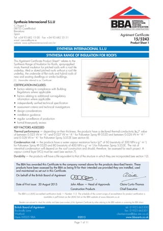
Agrément Certificate 15/5243 Product Sheet 1. APPROVAL INSPECTION TESTING CERTIFICATION. TECHNICAL APPROVALS FOR CONSTRUCTION

Recommended
More Related Content
What's hot
What's hot (14)
Similar to Certificado BBA - Aislamiento Synthesia para cubiertas
Similar to Certificado BBA - Aislamiento Synthesia para cubiertas (20)
Recently uploaded
Recently uploaded (20)
Certificado BBA - Aislamiento Synthesia para cubiertas
- 1. Page 1 of 11 TECHNICAL APPROVALS FOR CONSTRUCTION APPROVAL INSPECTION TESTING CERTIFICATION Synthesia Internacional S.L.U C/Argent 3 08755 Castellbisbal Barcelona Spain Tel: +34 93 682 13 00 Fax: +34 93 682 35 51 e-mail: cservice@synte.es website: www.synthesiainternacional.com/en British Board of Agrément tel: 01923 665300 Bucknalls Lane fax: 01923 665301 Watford clientservices@bba.star.co.uk Herts WD25 9BA www.bbacerts.co.uk©2015 The BBA is a UKAS accredited certification body — Number 113. The schedule of the current scope of accreditation for product certification is available in pdf format via the UKAS link on the BBA website at www.bbacerts.co.uk Readers are advised to check the validity and latest issue number of this Agrément Certificate by either referring to the BBA website or contacting the BBA direct. SYNTHESIA INTERNACIONAL S.L.U SYNTHESIA RANGE OF INSULATION FOR ROOFS This Agrément Certificate Product Sheet(1) relates to the Synthesia Range of Insulation for Roofs, spray-applied in-situ thermal insulation for pitched roofs with a roof tile underlay, tiled or slated pitched roofs without a roof tile underlay, the underside of flat roofs and hybrid roofs of new and existing dwellings or similar buildings. (1) Hereinafter referred to as ‘Certificate’. CERTIFICATION INCLUDES: • factors relating to compliance with Building Regulations where applicable • factors relating to additional non-regulatory information where applicable • independently verified technical specification • assessment criteria and technical investigations • design considerations • installation guidance • regular surveillance of production • formal three-yearly review. KEY FACTORS ASSESSED Thermal performance — depending on their thickness, the products have a declared thermal conductivity (D )* value of between 0.025 W·m–1 ·K–1 and 0.027 W·m–1 ·K–1 for Poliuretan Spray RF-352D and between 0.026 W·m–1 ·K–1 and 0.028 W·m–1 ·K–1 for Poliuretan Spray S-353E (see section 6). Condensation risk — the products have a water vapour resistance factor (μ)* of 60 (resistivity of 300 MN·s·g–1 ·m–1 ) for Poliuretan Spray RF-352D and 80 (resistivity of 400 MN·s·g–1 ·m–1 ) for Poliuretan Spray S-353E. The risk of interstitial condensation will depend on the roof construction and should, therefore, be assessed for each project. A vapour control layer (VCL) must be used (see section 7). Durability — the products will have a life equivalent to that of the structure in which they are incorporated (see section 12). Agrément Certificate 15/5243 Product Sheet 1 The BBA has awarded this Certificate to the company named above for the products described herein. These products have been assessed by the BBA as being fit for their intended use provided they are installed, used and maintained as set out in this Certificate. On behalf of the British Board of Agrément Date of First issue: 20 August 2015 John Albon — Head of Approvals Claire Curtis-Thomas Construction Products Chief Executive
- 2. Page 2 of 11 In the opinion of the BBA, the Synthesia Range of Insulation for Roofs, if installed, used and maintained in accordance with this Certificate, can satisfy or can contribute to satisfying the relevant requirements of the following Building Regulations (the presence of a UK map indicates that the subject is related to the Building Regulations in the region or regions of the UK depicted): The Building Regulations 2010 (England and Wales) (as amended) Requirement: C2(c) Resistance to moisture Comment: The products can contribute to satisfying this Requirement. See sections 7.1 and 7.7 of this Certificate. Requirement: L1(a)(i) Conservation of fuel and power Comment: The products can contribute to satisfying this Requirement. See section 6 of this Certificate. Regulation: 7 Materials and workmanship Comment: The products are acceptable. See section 12 and the Installation part of this Certificate. Regulation: 26 CO2 emission rates for new buildings Regulation: 26A Fabric energy efficiency rates for new dwellings (applicable to England only) Regulation: 26A Primary energy consumption rates for new buildings (applicable to Wales only) Regulation: 26B Fabric performance values for new dwellings (applicable to Wales only) Comment: The products can contribute to satisfying these Regulations; however, compensating fabric/services measures may be required. See section 6 of this Certificate. The Building (Scotland) Regulations 2004 (as amended) Regulation: 8(1) Durability, workmanship and fitness of materials Comment: The products are acceptable. See section 12 and the Installation part of this Certificate. Regulation: 9 Building standards applicable to construction Standard: 3.15 Condensation Comment: The products can contribute to satisfying this Standard, with reference to clauses 3.15.1(1)(2) , 3.15.3(1)(2) , 3.15.4(1)(2) , 3.15.5(1)(2) and 3.15.7(1)(2) . See sections 7.1 and 7.8 of this Certificate. Standard: 6.1(b) Carbon dioxide emissions Standard: 6.2 Building insulation envelope Comment: The products can contribute to satisfying these Standards, with reference to clauses, or parts of, 6.1.1(1), 6.1.6(1), 6.2.1(1)(2), 6.2.3(1), 6.2.4(1)(2), 6.2.5(2), 6.2.6(1)(2), 6.2.7(1), 6.2.8(2), 6.2.9(1)(2), 6.2.10(1), 6.2.11(1)(2), 6.2.12(2) and 6.2.13(1)(2). See section 6 of this Certificate. Standard: 7.1(a)(b) Statement of sustainability Comment: The products can contribute to satisfying the relevant requirements of Regulation 9, Standards 1 to 6, and therefore will contribute to a construction meeting at least a bronze level of sustainability as defined in this Standard. See section 6 of this Certificate. Regulation: 12 Building standards applicable to conversions Comment: All comments given for these products under Regulation 9, Standards 1 to 6, also apply to this Regulation, with reference to clause 0.12.1(1)(2) and Schedule 6(1)(2). (1) Technical Handbook (Domestic). (2) Technical Handbook (Non-Domestic). The Building Regulations (Northern Ireland) 2012 (as amended) Regulation: 23 Fitness of materials and workmanship Comment: The products are acceptable. See section 12 and the Installation part of this Certificate. Regulation: 29 Condensation Comment: The products can contribute to satisfying this Regulation. See section 7.1 of this Certificate. Regulation: 39(a)(i) Conservation measures Regulation: 40(2) Target carbon dioxide emission rate Comment: The products can contribute to satisfying these Regulations. See section 6 of this Certificate. Construction (Design and Management) Regulations 2015 Construction (Design and Management) Regulations (Northern Ireland) 2007 Information in this Certificate may assist the client, Principal Designer/CDM co-ordinator, designer and contractors to address their obligations under these Regulations. See sections: 3 Delivery and site handling and 14 Precautions of this Certificate. Regulations
- 3. Page 3 of 11 Additional Information NHBC Standards 2014 NHBC accepts the use of the Synthesia Range of Insulation for Roofs, if installed, used and maintained in accordance with this Certificate, in relation to NHBC Standards, Chapter 7.2 Pitched roofs. CE marking The Certificate holder has taken the responsibility of CE marking the products, in accordance with harmonised European Standard EN 14315-1 : 2013. An asterisk (*) appearing in this Certificate indicates that data shown are given in the manufacturer’s Declaration of Performance. Technical Specification 1 Description 1.1 The Synthesia Range of Insulation for Roofs consists of Poliuretan Spray RF-352D and Poliuretan Spray S-353E, closed-cell polyurethane foams suitable for pitched roofs with a roof tile underlay, the underside of flat timber roofs and hybrid roofs. Poliuretan Spray RF-352D can also be applied directly to tiled or slated roofs. 1.2 The products are prepared from two liquid components, isocyanate and resin, and are yellowish in colour. 1.3 The products are applied with a fixed ratio (1:1) volumetric displacement pump, up to a maximum thickness of 200 mm or, when applied to slates or tiles, to a maximum thickness of 40 mm. 1.4 Ancillary items used with these products, but outside the scope of this Certificate include: • non-breathable and breathable roof underlays • vapour control layer (VCL) • gypsum plaster board • timber battens • spray equipment. 2 Manufacture 2.1 Poliuretan Spray is produced by a simple blending of components in a given proportion. The data are introduced into a computer program and the addition of the different components is automatic and controlled by the software. 2.2 As part of the assessment and ongoing surveillance of product quality, the BBA has: • agreed with the manufacturer the quality control procedures and product testing to be undertaken • assessed and agreed the quality control operated over batches of incoming materials • monitored the production process and verified that it is in accordance with the documented process • evaluated the process for management of nonconformities • checked that equipment has been properly tested and calibrated • undertaken to carry out the above measures on a regular basis through a surveillance process, to verify that the specifications and quality control operated by the manufacturer are being maintained. 2.3 The management system of the manufacturer has been assessed and registered as meeting the requirements of ISO 9001 : 2008 by Bureau Veritas (Certificate ES056037-B1). 3 Delivery and site handling 3.1 The isocyanate and resin components are delivered to site in drums (up to 250 kg capacity) bearing the product name, batch number and BBA Certificate number. 3.2 Drums should be stored in a well-ventilated area, ideally above 10°C, and away from possible ignition sources. The drums must be protected from frost. 3.3 The isocyanate component is classified under the Classification, Labelling and Packaging of Substances and Mixtures (CLP Regulation) 2009, and the packaging bears the appropriate hazard warning label(s). Assessment and Technical Investigations The following is a summary of the assessment and technical investigations carried out on the Synthesia Range of Insulation for Roofs.
- 4. Page 4 of 11 Design Considerations 4 Use 4.1 The Synthesia Range of Insulation for Roofs is satisfactory for use in reducing the thermal transmittance (U value) of roofs and lofts of dwellings or similar buildings. 4.2 The products can be used: • between, or between and under, timber rafters in a habitable warm pitched roof (room in the roof). Insulation at rafter level only • between, or between and under, timber rafters and between timber ceiling joists in a non-habitable hybrid pitched roof • between timber joists to the underside of a roof deck in flat timber roofs • between, or between and under, timber rafters directly to tiles or slates. 4.3 Poliuretan Spray RF-352D can also be used as an insulation/repair and stabilising system applied directly to slate or tiled pitched roofs suffering from the effects of nail corrosion. The anchorage originally supplied by the fixing nails is replaced by the adhesive properties of the foam (see Product Sheet 4 of this Certificate). 4.4 The products must be covered by a plasterboard lining except when used in a non-habitable loft space (see the Installation section in this Certificate); this use is restricted under the national Building Regulations (also see section 8.3). 4.5 Constructions must be designed in accordance with the relevant recommendations of: • BS 5250 : 2011 • BS 5534 : 2014 • BS 8103-3 : 2009 • BS EN 351-1 : 2007 • BS EN 1995-1-1 : 2004 and its UK National Annex. 4.6 It is essential that construction elements are designed and constructed to incorporate normal precautions against moisture ingress before the application of the product. 4.7 Existing constructions must be in a good state of repair with no evidence of rain penetration or damp. Defects must be made good prior to installation. 4.8 The products must not come into direct contact with flue pipes, chimneys or other heat-producing appliances (see section 9). 4.9 The products form a strong bond with clean, dry substrates. This should be taken into account when specifying the products or anticipating future alterations. 4.10 To satisfy the requirements of NHBC, a VCL of a type specified in their Standards must be applied behind the plasterboard lining in roof applications, and the products must only be applied to a roof construction incorporating a breathable roof tile underlay. Pitched roofs — tiled or slated to BS 5534 : 2014 4.11 Pitched roofs are defined for the purpose of this Certificate as those roofs having a pitch in excess of 15°. 4.12 The products can be spray-applied directly to the underside of reinforced bitumen membranes, breathable roof tile underlays, or timber sarking boards between the rafters. 4.13 Care must be taken to ensure the integrity of the roof tile underlay drape when spraying the products (refer to the Synthesia Installation and training manual). See section 15.5 of this Certificate. 5 Practicability of installation The products should only be installed by installers who have been trained and approved by the Certificate holder (see section 13). 6 Thermal performance 6.1 Calculations of the thermal transmittance (U value) of a roof should be carried out in accordance with BS EN ISO 6946 : 2007 and BRE Report BR 443 : 2006 using the declared thermal conductivity (D )* in Table 1 of this Certificate. Table 1 Thermal conductivity (D )* Insulation thickness (mm) Thermal conductivity (W∙m–1∙K–1) Poliuretan Spray RF-352D Poliuretan Spray S-353E 80 0.027 0.028 80 to 120 0.026 0.027 120 0.025 0.026
- 5. Page 5 of 11 6.2 The U value of a completed roof will depend on the insulation thickness and the roof structure and its internal finish. Example constructions are given in Tables 2 to 5. For improved energy or carbon savings, designers should consider appropriate fabric and/or services measures. Table 2 U values — Flat roofs Design U values (W∙m–2 ∙K–1 ) Insulation thickness(1) (mm) Poliuretan Spray S-353E(2)(3) Poliuretan Spray RF-352D(2)(3) 0.13 –(4) –(4) 0.16 –(4) –(4) 0.18 195(5) 190(5) 0.20 170(5) 165(5) 0.25 135(6) 130(6) (1) Thickness range of 30 mm to 200 mm with 5 mm increments. (2) Roof construction inclusive of bitumen, 18 mm plywood deck ( = 0.24 W∙m–1 ∙K–1 ), variable thickness of timber joists bridge (12.5%) containing a variable thickness of insulation (remaining thickness is air cavity), 12.5 mm plasterboard ( = 0.25 W∙m–1 ∙K–1 ). (3) It is assumed there is no air gap correction (Ug = 0.00). (4) For improved thermal/carbon emissions performance, additional batten/insulation thicknesses maybe considered. (5) U value achieved using 200 mm joists. (6) U value achieved using 150 mm joists. Table 3 U values — Pitched roof Design U values (W∙m–2 ∙K–1 ) Insulation thickness(1) (mm) Poliuretan Spray S-353E(2)(3) Poliuretan Spray RF-352D(2)(3) 0.13 –(4) –(4) 0.16 –(4) –(4) 0.18 200(5) 190(5) 0.20 170(5) 165(5) 0.25 135(6) 130(5) (1) Thickness range of 30 mm to 200 mm with 5 mm increments. (2) Roof construction inclusive of 15 mm concrete tiles, ventilated tile batten cavity (R = 0 m2 ∙kW–1 ), 1F roof felt, variable thickness of timber rafters bridge (12.5%) containing a variable thickness of insulation (remaining thickness is air cavity), 12.5 mm plasterboard ( = 0.25 W∙m–1 ∙K–1 ). (3) It is assumed there is no air gap correction (Ug = 0.00). (4) For improved thermal/carbon emissions performance, additional batten/insulation thicknesses maybe considered. (5) U value achieved using 200 mm rafters. (6) U value achieved using 150 mm rafters. Table 4 U values — Hybrid roof Design U values (W∙m–2 ∙K–1 ) Insulation thickness(1) (mm) Poliuretan Spray S-353E(2)(3) Poliuretan Spray RF-352D(2)(3) 0.13 –(4) –(4) 0.16 –(4) –(4) 0.18 200(5) 190(5) 0.20 170(5) 165(5) 0.25 135(6) 130(6) (1) Thickness range of 30 mm to 200 mm with 5 mm increments. (2) Roof construction inclusive of 15 mm concrete tiles, ventilated tile batten cavity (R = 0 m2 ∙kW–1 ), 1F roof felt, variable thickness of timber rafters bridge (12.5%) containing a variable thickness of insulation (remaining thickness is air cavity), 12.5 mm plasterboard ( = 0.25 W∙m–1 ∙K–1 ). (3) It is assumed there is no air gap correction (Ug = 0.00). (4) For improved thermal/carbon emissions performance, additional batten/insulation thicknesses maybe considered. (5) U value achieved using 200 mm rafters. (6) U value achieved using 150 mm rafters.
- 6. Page 6 of 11 Table 5 U values — Tiled and slated roof Design U values (W∙m–2∙K–1) Insulation thickness(1) (mm) Roof pitch angle: 20° Roof pitch angle: 30° Roof pitch angle: 40° Roof pitch angle: 50° Roof pitch angle: 60° S-353E(2)(3) RF-352D(2)(3) S-353E(2)(3) RF-352D(2)(3) S-353E(2)(3) RF-352D(2)(3) S-353E(2)(3) RF-352D(2)(3) S-353E(2)(3) RF-352D(2)(3) 0.13 –(4) –(4) –(4) –(4) –(4) –(4) –(4) –(4) –(4) –(4) 0.16 –(4) –(4) –(4) –(4) –(4) –(4) –(4) –(4) –(4) –(4) 0.18 –(4) –(4) –(4) –(4) –(4) –(4) –(4) –(4) –(4) –(4) 0.20 110 110 120 115 –(4) –(4) –(4) –(4) –(4) –(4) 0.25 65 60 70 65 85 80 105 100 –(4) –(4) (1) Maximum insulation thickness restricted to 120 mm (100 mm between and 20 mm above rafters, below tiles). (2) 15 mm concrete tiles ( = 1.50 W∙m–1∙K–1), 20 mm insulation between tile battens (6.0% = 0.13 W∙m–1∙K–1), variable insulation thickness between rafters (12.5% = 0.13 W∙m–1∙K–1), loft space (R = 0.20 m2∙kW–1), 100 mm ceiling joists (12.5% = 0.13 W∙m–1∙K–1) containing mineral wool ( = 0.044 W∙m–1∙K–1). (3) It is assumed there is an air gap correction of Ug = 0.04. (4) For improved thermal/carbon emissions performance, additional batten/insulation thicknesses maybe considered. Junctions 6.3 Care must be taken in the overall design and construction of junctions with other elements to minimise thermal bridges and air infiltration. Detailed guidance can be found in the documents supporting the national Building Regulations. 7 Condensation risk Interstitial condensation 7.1 Pitched roofs should be designed and constructed in accordance with the relevant parts of BS 5250 : 2011 and Annex D including having a well-sealed ceiling for the roof application [using a water vapour resistance factor* (µ) of 60 (resistivity of 300 MN·s·g–1 ·m–1 ) for Poliuretan Spray RF-352D and 80 (resistivity of 400 MN·s·g–1 ·m–1 ) for Poliuretan Spray S-353E]. 7.2 Care should be taken to provide adequate ventilation, particularly in rooms expected to experience high humidities, and to ensure the integrity of VCL’s (where installed) and linings against vapour ingress. 7.3 It is essential that the roof design, construction and maintenance limit opportunities for vapour migration by diffusion, and by convection through gaps, cracks and laps in air and/or VCL’s and through penetrations. 7.4 Dynamic simulations to BS EN 15026 : 2007 indicate that the vapour control layer properties (with sealed laps) detailed in Table 6 of this Certificate are acceptable in roofs with no penetrations. The suitability of other constructions may be assessed by using an appropriate dynamic modelling package (see section 16.2). Table 6 Vapour control layer properties VCL equivalent air layer thickness sd (m) VCL water vapour resistance (MN·s·g–1) Roof type 10 50 Flat roof 10 50 Hybrid pitched roof 50 250 Pitched roof 7.5 Fortuitous air infiltration in hybrid roofs contributes to reducing the risk of interstitial condensation. 7.6 Ventilation openings should be arranged to prevent the ingress of rain, snow, birds and small mammals and the risk of subsequent blockage by other building operations. Surface condensation 7.7 Roofs and loft spaces will limit the risk of surface condensation adequately where the thermal transmittance (U value) does not exceed 0.35 W·m–2 ·K–1 at any point and the junctions with other elements are designed in accordance with the guidance referred to in section 6.3 of this Certificate. 7.8 Constructions will be acceptable where the thermal transmittance (U) value of the roof does not exceed 1.2 W·m–2 ·K–1 at any point, and where they are designed and constructed in accordance with the relevant parts of BS 5250 : 2011, Annexes D and H. Further guidance may be obtained from BRE Report BR 262 : 2002.
- 7. Page 7 of 11 8 Behaviour in relation to fire 8.1 Poliuretan Spray S-353E is classified as Class E* and Poliuretan Spray RF-352D as D-s3,d0* to EN 13501-1 : 2007. The products are not classified as ‘non-combustible’ and must be protected from naked flames and other ignition sources during and after installation. 8.2 Once installed, except for the non-habitable loft application using Poliuretan Spray RF-352D (which is restricted under the national Building Regulations), the product must be contained by a suitable lining board, eg plasterboard, with joints fully sealed and supported by rafters, noggins or battens. Therefore, it will not contribute to the development stages of a fire. 8.3 Elements must incorporate cavity barriers at edges, around openings and at junctions with fire-resisting elements, and the maximum dimensions of any cavity in any direction must meet the requirements of the national Building Regulations. The design and installation of cavity barriers must take into account any anticipated differential movement. 9 Proximity of flues and appliances 9.1 When installing the products in close proximity to certain flue pipes, chimneys and/or heat-producing appliances, the relevant provisions of the national Building Regulations are applicable: England and Wales — Approved Document J Scotland — Mandatory Standard 3.19(1)(2) (1) Technical Handbook (Domestic). (2) Technical Handbook (Non-Domestic). Northern Ireland — Technical Booklet L. 9.2 The products must not be installed within 50 mm of heat-emitting devices where the temperature is in excess of 93°C. 10 Materials in contact — wiring installations 10.1 The products are compatible with PVC materials in contact. 10.2 De-rating of electric cables should be considered in areas where the products restrict the flow of air. The use of suitable conduit or trunking is recommended. 10.3 Where recessed lighting is used, provision should be made to prevent the fitting overheating, or ventilated fittings must be used. 11 Maintenance Once installed, the products do not require any regular maintenance and have suitable durability (see section 12), provided the waterproof layers are maintained in a weather-tight condition. 12 Durability The products will have a life equivalent to that of the structure in which they are incorporated. Installation 13 Approved installers The Certificate holder operates an Approved Installer Scheme for these products, under which the installers are approved, registered and regularly reviewed by the Certificate holder to demonstrate that they are competent to carry out installation of the products in accordance with their instructions and this Certificate. Details of Approved Installers are available from the Certificate holder. 14 Precautions 14.1 To comply with the requirements of Section 4 of the Health and Safety at Work Act 1974, it is essential that there is an exchange of information between the client and the installer before spray operations commence on any site. Existing health hazards and those brought into the premises by the installer should be discussed, and measures agreed to deal with them effectively. 14.2 The process for the installation of the products may produce a build-up of harmful vapours. Installers must wear full personal protection equipment (PPE) when working with the products, including full-face fresh-air-supplied respirators, protective clothing and chemical-resistant gloves. Other trades and personnel must be kept at least four metres away from the applicator while spraying is taking place. The requirements of the Synthesia Installation and training manual and the product safety data sheets issued to installers must be followed at all times. 14.3 Vapours given off by certain components are generally heavier than air and will tend to move to lower parts of the building. These parts should be suitably ventilated.
- 8. Page 8 of 11 14.4 If vapour levels need to be measured, methods should be those recommended by the Health and Safety Executive. Certain applications, eg confined roofs, require the use of extractor fans as recommended by the Certificate holder. 14.5 Whilst spraying, care should be taken to minimise the degree of ‘overspray’, a fine mist of particles that can travel considerable distances and adhere strongly to surfaces. 14.6 To prevent the products from entering an occupied space, the loft hatch/cover must be kept closed during the spraying process. Protective covers must be placed over water tanks to prevent contamination and blockage during application, and must not be removed until sufficient time has elapsed for potentially harmful vapours to be ventilated from the roof space. 15 Procedure General 15.1 Building elements to be insulated must be assessed for suitability and any necessary repairs carried out. Roofs must be weather tight before the application of the product. The positioning of, and access to, services should also be considered. 15.2 Access boards and lighting should be positioned in the roof void. 15.3 Where no provision is made for ventilation of the space, care should be taken to ensure that ingress of moisture- vapour from the dwelling space below is restricted. 15.4 Where additional insulation to that described in sections 15.5 and 15.6 is required, various forms of insulation, including Synthesia Insulation for Roofs, can be placed between the horizontal ceiling joists, after conducting a condensation risk analysis in accordance with section 6 of this Certificate. Warm pitched roof (habitable room in the roof, or non-habitable hybrid roof including insulation at horizontal ceiling level) — insulation between rafters only 15.5 The product is spray-applied to clean and dry substrates in a flash coat 10 mm thick. When sprayed to a roof tile underlay, care must be taken to ensure the integrity of the roof tile underlay drape. Subsequent coats not exceeding 20 mm thick are applied once the foam reaction has occurred, and within 10 minutes of the previous coat, until the required total thickness is achieved (see also section 7.4). Warm pitched roof (habitable room in the roof, or non-habitable hybrid roof including insulation at horizontal ceiling level) — insulation between and under rafters 15.6 The product is spray-applied to the depth of the rafters as in section 15.5. Cross-battens are then mechanically fixed to the rafters. The battens must be of sufficient width and spacing (up to 600 mm) to provide adequate support to which the plasterboard can be mechanically fixed, and then filling resumes in 20 mm layers (see also section 7.4). Figure 1 Typical pitched roof application Synthesia roof tile underlay cavity wall insulation insulation foil faced plasterboard Flat roof application 15.7 The product is spray-applied to clean and dry substrates in a flash coat 10 mm thick, directly to the underside of the roof deck. Subsequent coats not exceeding 20 mm thick are applied once the foam reaction has occurred, and within 10 minutes of the previous coat, until the required total thickness is achieved.
- 9. Page 9 of 11 Figure 2 Flat roof application weatherproof membrane joist 2 mm multi-finish plaster foil faced plasterboard plywood unvented air space Synthesia Tiles and slates application — insulation between rafters only (Poliuretan Spray RF-352D) 15.8 The product is spray-applied to the underside of slates/tiles between rafters in a flash coat 10 mm thick, starting at the eaves and working up towards the ridge, ensuring the void between the slates/tiles and the upper face of the rafters is completely filled. Subsequent coats not exceeding 20 mm thick are applied once the foam reaction has occurred, and within 10 minutes of the previous coat, until the total required thickness is achieved. 15.9 If the roof to be treated is cold and/or if there is a risk of tiles or slates lifting due to the pressure created by the foaming process, it is recommended that the first coat should not exceed a thickness of 5 mm. 15.10 Care must be taken not to apply the product to flue pipes, main roof trusses or electrical cables. 15.11 After completion, a survey should be performed to check that electrical cables and flues are not obstructed. Corrective measures must be taken to clear such obstruction. Tiles and slates application — insulation between and under rafters (Poliuretan Spray RF-352D) 15.12 The product is spray-applied to the depth of the rafters as in sections 15.8 and 15.9. Cross-battens are then mechanically fixed to the rafters. The battens must be of sufficient width and spacing (up to 600 mm) to provide adequate support to which the plasterboard can be mechanically fixed, and then filling resumes in 20 mm layers. Technical Investigations 16 Investigations 16.1 An assessment was made of independent data relating to: • thermal conductivity • behaviour in relation to fire • water vapour permeability. 16.2 A series of dynamic computer simulations to BS EN 15026 : 2007 were carried out on a range of roof constructions to assess the risk of interstitial condensation. The simulations included building humidity class 4, meteorological data for solar irradiation (direct and indirect) and rainfall for standard reference years, material moisture storage functions, porosity, specific heat capacity and long-term projections of material moisture contents. 16.3 The manufacturing process was evaluated, including the methods adopted for quality control, and details were obtained of the quality and composition of the materials used.
- 10. Page 10 of 11 Bibliography BS 5250 : 2011 Code of practice for control of condensation in buildings BS 5534 : 2014 Code of practice for slating and tiling (including shingles) BS 8103-3 : 2009 Structural design of low-rise buildings — Code of practice for timber floors and roofs for housing BS EN 351-1 : 2007 Durability of wood and wood-based products — Preservative-treated solid wood — Classification of preservative penetration and retention BS EN 1995-1-1 : 2004 Eurocode 5 : Design of timber structures — General — Common rules and rules for buildings NA to BS EN 1995-1-1 : 2004 UK National Annex to Eurocode 5 : Design of timber structures — General — Common rules and rules for buildings BS EN 13501-1 : 2007 Fire classification of construction products and building elements — Classification using test data from reaction to fire tests BS EN 15026 : 2007 Hygrothermal performance of building components and building elements — Assessment of moisture transfer by numerical simulation BS EN ISO 6946 : 2007 Building components and building elements — Thermal resistance and thermal transmittance — Calculation method EN 14315-1 : 2013 Thermal insulating products for buildings — In-situ formed sprayed rigid polyurethane (PUR) and polyisocyanurate (PIR) foam products — Specification for the rigid foam spray system before installation ISO 9001 : 2008 Quality management systems — Requirements BRE Report (BR 262 : 2002) Thermal insulation: avoiding risks BRE Report (BR 443 : 2006) Conventions for U-value calculations
- 11. Page 11 of 11 Conditions of Certification 17 Conditions 17.1 This Certificate: • relates only to the product/system that is named and described on the front page • is issued only to the company, firm, organisation or person named on the front page — no other company, firm, organisation or person may hold or claim that this Certificate has been issued to them • is valid only within the UK • has to be read, considered and used as a whole document — it may be misleading and will be incomplete to be selective • is copyright of the BBA • is subject to English Law. 17.2 Publications, documents, specifications, legislation, regulations, standards and the like referenced in this Certificate are those that were current and/or deemed relevant by the BBA at the date of issue or reissue of this Certificate. 17.3 This Certificate will remain valid for an unlimited period provided that the product/system and its manufacture and/or fabrication, including all related and relevant parts and processes thereof: • are maintained at or above the levels which have been assessed and found to be satisfactory by the BBA • continue to be checked as and when deemed appropriate by the BBA under arrangements that it will determine • are reviewed by the BBA as and when it considers appropriate. 17.4 The BBA has used due skill, care and diligence in preparing this Certificate, but no warranty is provided. 17.5 In issuing this Certificate, the BBA is not responsible and is excluded from any liability to any company, firm, organisation or person, for any matters arising directly or indirectly from: • the presence or absence of any patent, intellectual property or similar rights subsisting in the product/system or any other product/system • the right of the Certificate holder to manufacture, supply, install, maintain or market the product/system • actual installations of the product/system, including their nature, design, methods, performance, workmanship and maintenance • any works and constructions in which the product/system is installed, including their nature, design, methods, performance, workmanship and maintenance • any loss or damage, including personal injury, howsoever caused by the product/system, including its manufacture, supply, installation, use, maintenance and removal • any claims by the manufacturer relating to CE marking. 17.6 Any information relating to the manufacture, supply, installation, use, maintenance and removal of this product/ system which is contained or referred to in this Certificate is the minimum required to be met when the product/system is manufactured, supplied, installed, used, maintained and removed. It does not purport in any way to restate the requirements of the Health and Safety at Work etc. Act 1974, or of any other statutory, common law or other duty which may exist at the date of issue or reissue of this Certificate; nor is conformity with such information to be taken as satisfying the requirements of the 1974 Act or of any statutory, common law or other duty of care. British Board of Agrément tel: 01923 665300 Bucknalls Lane fax: 01923 665301 Watford clientservices@bba.star.co.uk Herts WD25 9BA www.bbacerts.co.uk©2015