SlideShare une entreprise Scribd logo
1  sur  48
WHAT IS MATERIALS ENGINEERING?
• It is the field of engineering that encompasses the spectrum of materials types and how to use
them in manufacturing.
• Materials engineering is different from Materials science. Materials science involves
investigating the relationships that exist between the structures and properties of
materials, whereas, Materials engineering, on the basis of these structure–property
correlations, design or engineer the structure of a material to produce a predetermined set of
properties. From a functional perspective, the role of a materials scientist is to develop or
synthesize new materials, whereas a materials engineer is called upon to create new products or
systems using existing materials, and/or to develop techniques for processing materials.
What is a Material?
• Everything we see and use is made of materials
• Engineers make things.
• They make them out of materials.
Why Study Materials Engineering?
In order to be a good designer, an engineer must learn what materials will be appropriate to use in
different applications.
Any engineer can look up materials properties in a book or search databases for a material that
meets design specifications, but the ability to innovate and to incorporate materials safely in a
design is rooted in an understanding of how to manipulate materials properties and functionality
through the control of the material’s structure and processing techniques.
Engineering
                                   Materials

   Metals &        Ceramics                                               Advanced
                                    Polymers        Composites
    Alloys         & Glasses                                              Materials
Metals and Alloys
Atoms in metals and their alloys are arranged in a very orderly manner, and in comparison
to the ceramics and polymers, are relatively dense . Metals have High electrical
conductivity, good formability, Castable, machinable. An alloy is a metal that contains
additions of one or more metals or non-metals. Metals and alloys have relatively high
strength, high stiffness, ductility or formability, and shock resistance.
Ceramics
Thermally insulating, Refractories. Ceramics can be defined as inorganic crystalline
materials. Beach sand and rocks are examples of naturally occurring ceramics. Traditional
ceramics are used to make bricks, tableware, toilets, bathroom sinks, refractories (heat-
resistant material), and abrasives. In general, due to the presence of porosity (small
holes), ceramics do not conduct heat well; they must be heated to very high temperatures
before melting. Ceramics are strong and hard, but also very brittle. Advanced ceramics
are materials made by refining naturally occurring ceramics and other special processes.
Glasses
Optically transparent. Glass is an amorphous material, often, but not always, derived from
a molten liquid. The term ―amorphous‖ refers to materials that do not have a regular,
periodic arrangement of atoms.
Polymers (Greek; Polys + meros = many + parts)
Polyethylene Food packaging Easily formed into thin, flexible, airtight film. Electrically insulating
and moisture-resistant. Polymers are typically organic materials. They are produced using a
process known as polymerization. Polymeric materials include rubber (elastomers), PE, nylon,
PVC, PC, PS, and silicone rubber. and many types of adhesives. Polymers typically are good
electrical and thermal insulators although there are exceptions such as the semiconducting
polymers
Composites
The main idea in developing composites is to blend the properties of different materials. The
design goal of a composite is to achieve a combination of properties that is not displayed by any
single material, and also to incorporate the best characteristics of each of the component
materials.
Advanced Materials
Semiconductors
Used in Silicon Transistors and integrated circuits. Unique electrical behaviour, converts electrical
signals to light, lasers, laser diodes, etc.
Biomaterials
Biomaterials are employed in components implanted into the human body to replace diseased or
damaged body parts. These materials must not produce toxic substances and must be compatible
with body tissues (i.e., must not cause adverse biological reactions).
Smart Materials
These materials are able to sense changes in their environment and then respond to these
changes in predetermined manners. Smart material include some type of sensors, and actuators.
Piezoelectric actuators expand and contract in response to an applied electric field .
Nanomaterials
Nanomaterials may be any one of the four basic types; metals, ceramics, polymers, & composites.
One common item that presents some interesting material property requirements is
the container for carbonated beverages. The material used for this application must
satisfy the following constraints: (1) provide a barrier to the passage of carbon
dioxide, which is under pressure in the container; (2) be nontoxic, non-reactive with
the beverage, and, preferably, recyclable; (3) be relatively strong and capable of
surviving a drop from a height of several feet when containing the beverage; (4) be
inexpensive, including the cost to fabricate the final shape; (5) if optically transparent,
retain its optical clarity; and (6) be capable of being produced in different colours
and/or adorned with decorative labels. All three of the basic material types—metal
(aluminium), ceramic (glass), and polymer (PE plastic)—are used for carbonated
beverage containers. All of these materials are non- toxic and un-reactive with
beverages. In addition, each material has its pros and cons. For example, the
aluminium alloy is relatively strong (but easily dented), is a very good barrier to the
diffusion of carbon dioxide, is easily recycled, cools beverages rapidly, and allows
labels to be painted onto its surface. On the other hand, the cans are optically opaque
and relatively expensive to produce. Glass is impervious to the passage of carbon
dioxide, is a relatively inexpensive material, and may be recycled, but it cracks and
fractures easily, and glass bottles are relatively heavy. Whereas plastic is relatively
strong, may be made optically transparent, is inexpensive and lightweight, and is
recyclable, it is not as impervious to the passage of carbon dioxide as the aluminium
and glass. For example, you may have noticed that beverages in aluminium and glass
containers retain their carbonization (i.e., ―fizz‖) for several years, whereas those in
two-litre plastic bottles ―go flat‖ within a few months.
The Figure shows three thin disk specimens placed over some printed matter. It is
obvious that the optical properties of each of the three materials are different; the one
on the left is transparent, whereas the disks in the center and on the right are,
respectively, translucent and opaque. All of these specimens are of the same
material, aluminum oxide, but the:
Leftmost one is what we call a single crystal—that is, it is highly perfect—which gives
rise to its transparency.
The center one is composed of numerous and very small single crystals that are all
connected; the boundaries between these small crystals scatter a portion of the light
reflected from the printed page, which makes this material optically translucent.
The specimen on the right is composed not only of many small, interconnected
crystals, but also of a large number of very small pores or void spaces. These pores
also effectively scatter the reflected light and render this material opaque.
Thus, the structures of these three specimens are different in terms of crystal
boundaries and pores, which affect the optical transmittance properties. Furthermore,
each material was produced using a different processing technique.
Crystalline Structure Of Metals
The properties of some materials are directly related to their crystal structures. The
crystalline structure of a material usually relates to the arrangement of its internal
Components.
Subatomic structure involves electrons within the individual atoms and interactions with
their nuclei.
Atomic structure involves arrangement of atoms in materials and defines interaction
among atoms (interatomic bonding).
Microscopic structure involves arrangement of small grains of material that can be
identified by microscopy.
Macroscopic structure relates to structural elements that may be viewed with the naked
eye.


                                                                       Macroscopic
                                                                       structure
                         Atomic level
 Subatomic level                              Microscopic structure
Each atom consists of a very small nucleus composed of protons and neutrons, which is
encircled by moving electrons. Both electrons and protons are electrically charged, the
charge magnitude being 1.62*10^-19 C, which is negative in sign for electrons and
positive for protons; neutrons are electrically neutral. Masses for these subatomic
particles are infinitesimally small; protons and neutrons have approximately the same
mass, 1.67*10^-27 kg, which is significantly larger than that of an electron, 9.11*10^-31
kg.
The atomic mass of a specific atom may be expressed as the sum of the masses of
protons and neutrons within the nucleus.
Body-Centered Cubic Crystal Structure


Face-Centered Cubic Crystal Structure


Hexagonal Close-Packed Crystal Structure
ATOMIC PACKING FACTOR

                                                               For BCC   APF 0.68
      Volume of atoms in unit cell
  APF                                                          For FCC   APF 0.74
           Volume unit cell
    Total number of atom s in unit cell Volume of unit atoms   For HCP    APF ?
                       Volume unit cell

 Show that the atomic packing factor for the BCC crystal structure is 0.68.
 Show that the atomic packing factor for the FCC crystal structure is 0.74.
 What is the atomic packing factor for the HCP crystal structure?.
 Show that for HCP the c/a ratio is 1.633
                                        3 3 a2
                  Area of a Hexagon
                                          2


 Numerical Problems
1. Calculate the volume of an BCC unit cell in terms of the atomic radius R.
2. Calculate the volume of an FCC unit cell in terms of the atomic radius R.
3. Calculate the volume of an HCP unit cell in terms of the atomic radius R.
Allotropy

Allotropy is the ability of an element to exist in different structural forms while in the
same state of matter. The allotropes depend on both the allotropy temperature and
the external pressure. For example, the allotropes of carbon include diamond (where
the carbon atoms are bonded together in a tetrahedral lattice arrangement),
graphite (where the carbon atoms are bonded together in sheets of a hexagonal
lattice). Graphite is the stable polymorph at ambient conditions, whereas diamond is
formed at extremely high pressures. Also, pure iron has a BCC crystal structure at
room temperature, which changes to FCC iron at 912◦ C
Crystallographic Directions, and Planes
Deformation under loading (slip) occurs on certain crystalline planes and in certain
crystallographic directions. Before we can predict how materials fail, we need to know
what modes of failure are more likely to occur.
• It is often necessary to be able to specify certain directions and planes in crystals.
• Many material properties and processes vary with direction in the crystal.
• Directions and planes are described using three integers; Miller Indices

   Method of describing Miller indices for Directions
 • Draw vector, and find the coordinates of the head, h1,k1,l1
 and the tail h2,k2,l2.
 • Subtract coordinates of tail from coordinates of head
 • Remove fractions by multiplying by smallest possible factor
 • Enclose in square brackets
Draw the following direction vectors in cubic unit cells:
(a) [100] and [110]         (b) [112]
(c) [110]                   (d) [321]

(a) The position coordinates for the direction indices [100] and [110] direction are (1, 0,
0) and (1, 1, 0), respectively (Fig. a).
(b) The position coordinates for the [112] direction are obtained by dividing the
direction indices by 2 so that they will lie within the unit cube. Thus the position
coordinates are (1/2,1/2,1) (Fig. b).
(c) The position coordinates for the [Ī10] direction are (-1, 1, 0) (Fig. c). Note that the
origin for the direction vector must be moved to the lower-left front corner of the cube.
(d) The position coordinates for the[321] direction are obtained by first dividing
all the indices by 3, the largest index. This gives -1,-2/3,-1/3 which are shown in Fig. d.
Method of describing Miller indices for Planes
The procedure for determining the Miller indices for a cubic crystal plane is as follows:
1. Choose a plane that does not pass through the origin at (0, 0, 0).
2. Determine the intercepts of the plane in terms of the crystallographic x, y, and z
axes for a unit cube. These intercepts may be fractions.
3. Form the reciprocals of these intercepts.
4. Clear fractions and determine the smallest set of whole numbers that are in the
same ratio as the intercepts. These whole numbers are the Miller indices of the
crystallographic plane and are enclosed in parentheses without the use of commas.
The notation (hkl) is used to indicate Miller indices in a general sense, where h, k, and
l are the Miller indices of a cubic crystal plane for the x, y, and z axes, respectively.


Draw the following crystallographic planes in cubic unit cells:
(a) (101) (b) (110) (c) (221)
Point defects: (a) vacancy, (b) interstitial atom, (c) small substitutional atom,
(d) large substitutional atom, (e) Frenkel defect, and (f) Schottky defect.
Vacancies: A vacancy is produced when an atom or an ion is missing from its
normal site in the crystal structure. When atoms or ions are missing (i.e., when
vacancies are present), the overall randomness or entropy of the material increases,
which increases the thermodynamic stability of a crystalline material. All crystalline
materials have vacancy defects. Vacancies are introduced into metals and alloys
during solidification, at high temperatures, or as a consequence of radiation damage.

Interstitial Defects: An interstitial defect is formed when an extra atom or ion is
inserted into the crystal structure at a normally unoccupied position. Interstitial atoms
such as hydrogen are often present as impurities, whereas carbon atoms are
intentionally added to iron to produce steel.

A substitutional defect is introduced when one atom or ion is replaced by a different
type of atom or ion.

A Frenkel defect is a vacancy-interstitial pair formed when an ion jumps from a
normal lattice point to an interstitial site.

A Schottky defect, is unique to ionic materials and is commonly found in many
ceramic materials. When vacancies occur in an ionically bonded material, a
stoichiometric number of anions and cations must be missing from regular atomic
positions if electrical neutrality is to be preserved. For example, one Mg+2 vacancy
and one O-2 vacancy in MgO constitute a Schottky pair.
Iron ores are rocks and minerals from which metallic iron can be economically
extracted. The ores are usually rich in iron oxides and vary in colour from dark grey,
bright yellow, deep purple, to rusty red. The iron itself is usually found in the form of
magnetite (Fe3O4), hematite (Fe2O3), goethite (FeO(OH)), limonite (FeO(OH)n(H2O))
or siderite (FeCO3).
Smelting
To convert it to metallic iron it must be smelted or sent through a direct reduction
process to remove the oxygen. Oxygen-iron bonds are strong, and to remove the iron
from the oxygen, a stronger elemental bond must be presented to attach to the
oxygen. Carbon is used because the strength of a carbon-oxygen bond is greater
than that of the iron-oxygen bond, at high temperatures. Thus, the iron ore must be
powdered and mixed with coke, to be burnt in the smelting process.
Iron Pure iron rarely exists outside of the laboratory. Iron is produced by reducing iron ore to pig
iron through the use of a blast furnace. From pig iron many other types of iron and steel are
produced by the addition or deletion of carbon and alloys. The following paragraphs discuss the
different types of iron and steel that can be made from iron ore.

PIG IRON.— Pig iron is composed of about 93% iron, from 3% to 5% carbon, and various
amounts of other elements. Pig iron is comparatively weak and brittle; therefore, it has a limited
use and approximately ninety percent produced is refined to produce steel. Cast-iron pipe and
some fittings and valves are manufactured from pig iron.
Carbon 3.0–4.5%
Manganese 0.15–2.5%
Phosphorus 0.1–2.0%
Silicon 1.0–3.0%
Sulphur 0.05–0.1%

WROUGHT IRON.— Wrought iron is made from pig iron with some slag mixed in during
manufacture. Almost pure iron, the presence of slag enables wrought iron to resist corrosion and
oxidation. The chemical analyses of wrought iron and mild steel are just about the same. The
difference comes from the properties controlled during the manufacturing process. Wrought iron
can be gas and arc welded, machined, plated, and easily formed; however, it has a low hardness
and a low-fatigue strength.

CAST IRON.— Cast iron is any iron containing greater than 2% carbon alloy. Cast iron has a
high compressive strength and good wear resistance; however, it lacks ductility, malleability, and
impact strength.
Iron Ore

Wrought
 Iron
          Pig Iron
All of the phosphorus and most of the manganese will enter the molten iron. Oxides of
silicon and sulphur compounds are partially reduced, and these elements also become
part of the resulting metal. Other contaminant elements, such as calcium, magnesium,
and aluminium, are collected in the limestone-based slag and are largely removed
from the system. The resulting pig iron tends to have roughly the following
composition:

Carbon 3.0–4.5%
Manganese 0.15–2.5%
Phosphorus 0.1–2.0%
Silicon 1.0–3.0%
Sulphur 0.05–0.1%
Conventional Blast Furnace
Modern Blast Furnace
1: Iron ore + Calcareous sinter
2: coke
3: conveyor belt
4: feeding opening, with a valve
that prevents direct contact with the
internal parts of the furnace
5: Layer of coke
6: Layers of sinter, iron oxide
pellets, ore,
7: Hot air (around 1200°C)
8: Slag
9: Liquid pig iron
10: Mixers
11: Tap for pig iron
12: Dust cyclon for removing dust
from exhaust gasses before
burning them in 13
13: Air heater
14: Smoke outlet (can be
redirected to carbon capture &
storage (CCS) tank)
15: feed air for Cowper air heaters
16: Powdered coal
17: cokes oven
18: cokes bin
19: pipes for blast furnace gas
PRODUCTION OF IRON

Iron is the fourth most plentiful element in the earth’s crust, it is rarely found in the
metallic state. Instead, it occurs in a variety of mineral compounds, known as ores, the
most attractive of which are iron oxides coupled with companion impurities. To produce
metallic iron, the ores are processed in a manner that breaks the iron–oxygen bonds.
Ore, limestone, coke (carbon), and air are continuously introduced into specifically
designed furnaces and molten metal is periodically withdrawn.

The production of iron in a blast furnace is a continuous process. The furnace is heated
constantly and is re-charged with raw materials from the top while it is being tapped from
the bottom. Iron making in the furnace usually continues for about ten years before the
furnace linings have to be renewed.

 Blast furnace is a furnace for smelting of iron from iron oxide ores (hematite,
 Fe2O3 or magnetite, Fe3O4). Coke, limestone and iron ore are poured in the top,
 which would normally burn only on the surface. The hot air blast to the furnace
 burns the coke and maintains the very high temperatures that are needed to reduce
 the ore to iron. The reaction between air and the fuel generates carbon monoxide.
 This gas reduces the iron oxide in the ore to iron.

 Fe2O3(s) + CO(g)    Fe(s) + CO2(g)
BLAST FURNACE CHEMISTRY FOR THE PRODUCTION OF IRON
The significant reactions occurring within the Blast Furnace can be described as follows:
1. Iron is extracted from its ores by the chemical reduction of iron oxides with carbon in a
furnace at a temperature of about 800 C - 1900 C.
2. Coke, the source of chemical energy in the blast furnace, is burnt both to release heat energy
and to provide the main reducing agent:
3. Calcium oxide, formed by thermal decomposition of limestone, reacts with the silicon oxide
present in sand, a major impurity in iron ores, to form slag (which is less dense than molten iron).
Overall, the chemical processes can be summarized by these equations:

     At 500o C
     3Fe2O3 +CO -> 2Fe3O4 + CO2
     Fe2O3 +CO -> 2FeO + CO2

     At 850o C
     Fe3O4 +CO -> 3FeO + CO2

     At 1000o C
     FeO +CO -> Fe + CO2
     At 1300 oC
     CO2 + C -> 2CO
     At 1900o C
     C+ O2 -> CO2
     FeO +C -> Fe + CO
PRODUCTION OF STEEL
  When iron is smelted from its ore by commercial processes, it contains more carbon than is
  desirable. In order to convert the pig iron into steel, it must be melted and reprocessed to
  reduce the carbon to the correct amount, at which point other elements can be added. This
  liquid is then continuously cast into long slabs or cast into ingots. Approximately 96% of steel
  is continuously cast, while only 4% is produced as cast steel ingots. The ingots are then heated
  in a soaking pit and hot rolled into slabs, blooms, or billets. Slabs are hot or cold
  rolled into sheet metal or plates. Billets are hot or cold rolled into bars, rods, and wire. Blooms
  are hot or cold rolled into structural steel, such as I-beams and rails. In modern foundries these
  processes often occur in one assembly line, with ore coming in and finished steel coming
  out. Sometimes after steel’s final rolling it is heat treated for strength, however this is
  relatively rare.
  Iron as obtained from blast furnace
  contains from 3-4% of Carbon, and
  variable amount of silicon, manganese
  sulphur and phosphorus.


1. Dead mild steel — up to 0.15% carbon
2. Low carbon or mild steel — 0.15% to 0.45% carbon
3. Medium carbon steel — 0.45% to 0.8% carbon
4. High carbon steel — 0.8% to 1.5% carbon
STEEL MAKING PROCESSES

 Bessemer Process
 Crucible Process
 Open Hearth Process
 Electric Process (Arc, Induction)
 Duplex Process
 Linz Donnawitz Process
 Kaldo Process
 Modern Process
Bessemer Process
Bessemer process was invented in1875 by Thomas Gilchrest. In Bessemer process
the molten pig iron from blast furnace is poured into converter. The converter is
made of steel plates lined inside with refractory material. In the bottom of converter
vessels, a no of holes are introduced through which air is blown at a pressure of
200-250KN/m2. Based on full capacity, the converter is charged with 100-150 ton,
and this charge is carried out from 10 to 15 ton at different time intervals. Their first
oxidizes silicon, and manganese which together with iron oxide rise to the top from
slag. During this air blowing process the carbon begins to burn and blowing
continued, until 0.25% of carbon is eliminated. In Bessemer process acids are used
to burn and eliminated silicon and phosphorus. The finished steel is then poured into
ladles and from ladle it is poured into ingot moulds for subsequently rolling and
forging process.
Crucible Process
In Crucible process wrought iron together with a small amount of pig iron, necessary
alloying metals and slagging materials are placed in a clay or clay-graphite
crucible, covered with an old crucible bottom and melted in a gas or coke-fired
furnace. After the charge is entirely molten, with sufficient time allowed for the gases
and impurities to rise to the surface, the Crucible is withdrawn, the slag removed
with a cold iron bar, and the resulting steel poured into a small ingot which is
subsequently forged to the desire shape.
There are three types of Crucible Furnaces:
(a) lift-out crucible,
(b) stationary pot, from which molten metal must be ladled, and
(c) tilting-pot furnace
Open Hearth Process
The open-hearth furnace is rectangular and rather low, holding from 15 to 200 ton of
metal in a saucer-like shallow pool. It is heated either by producer gas, oil, tar, mixed
blast furnace and coke oven gas, pitch, mixture of creosote and pitch and heavy fuel
oil. Flames come from first one end and then the other. Waste gases pass through
regenerators. The furnace is charged with ore and limestone. The lime stone begins
to decompose in carbon di-oxide and calcium oxide.


A. gas and air enter
B. pre-heated chamber
C. molten pig iron
D. hearth
E. heating chamber
F. gas and air exit.
Electric Furnace
An Electric Arc Furnace (EAF) is a furnace that heats charged material by means
of an electric arc. An electric arc furnace used for steelmaking consists of
a refractory-lined vessel, usually water-cooled in larger sizes, covered with a
retractable roof, and through which one or more graphite electrodes enter the
furnace. Arc furnaces differ from induction furnaces in that the charge material is
directly exposed to an electric arc, and the current in the furnace terminals passes
through the charged material.
An induction furnace is an electrical furnace in which the heat is applied
by induction heating of metal. The advantage of the induction furnace is a clean,
energy-efficient and well-controllable melting process compared to most other
means of metal melting.
The one major drawback to Electric furnace usage in a foundry is the lack of refining
capacity; charge materials must be clean of oxidation products and of a known
composition and some alloying elements may be lost due to oxidation.
 Induction furnace is based on the principle of heating by induced currents. If a conductor is
placed within a coil through which an alternating current is flowing, a current is induced in the
conductor. By the normal la of electricity this conductor is heated. The magnitude of the current
generated depends on:
_the physical dimensions of the coil;
_the resistivity of the conductor and
_the frequency of the current.
Linz-Donawitz (LD) or Basic oxygen steel making (BOS) Process
The basic oxygen steel-making process is as follows:
1. Molten pig iron from a blast furnace is poured into a large refractory-lined container
   called a ladle. Besides the BOS vessel is one-fifth filled with steel scrap.
2. The metal in the ladle is sent directly for basic oxygen steelmaking or to a pre-
   treatment stage. Pre-treatment of the blast furnace metal is used to reduce the
   refining load of sulphur, silicon, and phosphorus. In desulfurising pre-treatment,
   several hundred kilograms of powdered magnesium are added. Sulphur impurities
   are reduced to magnesium sulphide in a violent exothermic reaction. The sulphide is
   then raked off. Similar pre-treatment is possible for desiliconisation and
   dephosphorisation using lime as reagents. The decision to pretreat depends on the
   quality of the blast furnace metal and the required final quality of the BOS steel.
3. Fluxes (lime or dolomite) are fed into the vessel to form slag, which absorbs
   impurities of the steelmaking process. During blowing the metal in the vessel forms
   an emulsion with the slag, facilitating the refining process.
Kaldo Process:
The Kaldo process, is a modification of LD process. It was originally developed in Sweden by Prof.
Kalling. This process is based on the advantage of evolution of heat by high phosphorus(2%) pig
iron to as low as 0.02% P.
The converter in Kaldo Process is inclined at 150 to 200 with the horizontal, and rotated at a speed
of 25-30 r.p.m. The oxygen lance is introduced through the open end of the vessel, which also acts
as the outlet for the exhaust gases. The use of oxygen allows simultaneous removal of carbon and
phosphorus from the (p 1.85%) pig iron. The rotation of the converter ensures better slag-metal
reaction.
MODERN STEEL MAKING PROCESS
Vacuum Induction Melting process:
This process is similar to the induction melting process with suitable arrangement for creating a
vacuum. This process is used for making super alloys containing nickel and cobalt as base metals.
It is very suitable process for further remelting for investment casting. Due to vacuum prevailing in
the chamber , non-metallic inclusions can be minimized and composition of chemically reactive
elements like titanium , boron and aluminium can be controlled accurately. New alloys of steel
possessing greater uniformly and reproducibility of properties accompanied by greater strength,
creep resistance, etc can be produced.
Consumable Electrical Vacuum Arc Melting Process:
 It is direct arc steel melting process in which the electrode is consumed during melting. This
process was originally used for titanium. Since this process eliminates hydrogen, oxygen, and
volatile materials, it is extensively used for special-purpose steels, as in moving parts of aircraft
engines, due to need of high strength, uniformity of properties, greater toughness and freedom from
tramp and volatile elements.
Electric slag refining (ESR) Process:
This process is commonly known as ESR. It is a larger form of the original welding process . It is the
electrical resistance heating process that remelts the preformed electrode into a water-cooled
crucible. Due to resistance to flow of current, the metal melts and drops onto the crucible through a
layer of slag around the ingot. The process is used for making high alloy, high quality steels for
obtaining superior properties normally not achieved in conventional processing. For example, ultra
high strength weldable steel.
EQUILIBRIUM PHASE DIAGRAM

A phase may be defined as a homogeneous portion of a
system that has uniform physical and chemical
characteristics.


One-component or Unary Phase Diagram
(P-T Diagram)
An equilibrium phase diagram is a graphic mapping of
the natural tendencies of a material or a material
system, assuming that equilibrium has been attained
for all possible conditions. There are three primary
variables          to         be          considered:
temperature, pressure, and composition. The simplest
phase diagram is a pressure–temperature (P–T)
diagram for a fixed-composition material. Areas of the
diagram are assigned to the various phases, with the
boundaries indicating the equilibrium conditions of
transition.
P–T phase diagrams are rarely used for engineering applications. Most engineering
processes are conducted at atmospheric pressure, and variations are more likely to
occur in temperature and composition.
COMPLETE SOLUBILITY IN BOTH LIQUID AND SOLID STATES
The upper line is the liquidus line, the lowest temperature for which the material is 100%
liquid. Above the liquidus, the two materials form a uniform-chemistry liquid solution. The
lower line, denoting the highest temperature at which the material is completely solid, is
known as a solidus line. Below the solidus, the materials form a solid-state solution in
which the two types of atoms are uniformly distributed throughout a single crystalline
lattice. Between the liquidus and solidus is a freezing range, a two-phase region where
liquid and solid solutions coexist.


                                                            Binary Phase Diagram
CONDITIONS FOR UNLIMITED SOLID SOLUBILITY
1. Size factor: The atoms or ions must be of similar size, with no more than a 15%
difference in atomic radius.
2. Crystal structure: The materials must have the same crystal structure; otherwise,
there is some point at which a transition occurs from one phase to a second phase with
a different structure.
3. Valence: The ions must have the same valence; otherwise, the valence electron
difference encourages the formation of compounds rather than solutions.
INTERPRETATION OF PHASE DIAGRAMS
In a phase diagram, for each point of temperature and composition, following three
pieces of information can be obtained:
1. The phases present: The stable phases can be determined by simply locating the
point of consideration on the temperature–composition mapping and identifying the
region of the diagram in which the point appears.
2. The composition of each phase: If the point lies in a two-phase region, a tie-line
must be constructed. A tie-line is simply an isothermal (constant-temperature) line drawn
through the point of consideration, terminating at the boundaries of the single phase
regions on either side. The compositions where the tie-line intersects the neighbouring
single-phase regions will be the compositions of those respective phases in the two-
phase mixture.
2. Amount of each phase:
1. The tie line is constructed across the two-phase region at the temperature of the alloy.
2. The overall alloy composition is located on the tie line.
3. The fraction of one phase is computed by taking the length of tie line from the overall
alloy composition to the phase boundary for the other phase, and dividing by the total tie
line length.


4. The fraction of the other phase is determined in the same manner.
PARTIAL SOLID SOLUBILITY
Many materials do not exhibit complete solubility in the solid state. Each is often soluble
in the other up to a certain limit or saturation point, which varies with temperature.


INSOLUBILITY
If one or both of the components are totally insoluble in the other, the diagrams will also
reflect this phenomenon. The following Figure illustrates the case where component A is
completely insoluble in component B in both the liquid and solid states.
The three-phase reaction that occurs upon cooling through 183°C can be written as:


          The lead–tin phase diagram
Figure given below summarizes the various forms of three-phase reactions that may
occur in engineering systems, along with the generic description of the reaction shown
below the figures. These include the eutectic, peritectic, monotectic, and syntectic
reactions, where the suffix -ic denotes that at least one of the three phases in the
reaction is a liquid. If the same prefix appears with an -oid suffix, the reaction is of a
similar form but all phases involved are solids. Two such reactions are the eutectoid and
the peritectoid. The separation eutectoid produces an extremely fine two-phase mixture,
and the combination peritectoid reaction is very sluggish since all of the chemistry
changes must occur within (usually crystalline) solids.
If components A and B form a compound, and the compound cannot tolerate any
deviation from its fixed atomic ratio, the product is known as a stoichiometric
intermetallic compound and it appears as a single vertical line in the diagram
IRON–CARBON PHASE DIAGRAM
Steel, composed primarily of iron and carbon, is the most important of the engineering
metals. For this reason, the iron–carbon equilibrium diagram assumes special
importance. We normally are not interested in the carbon-rich end of the Fe-C phase
diagram and this is why the full iron–carbon (Fe-C) diagram is not normally encountered,
but we examine the Fe-Fe3C diagram as part of the Fe-C binary phase Diagram.
In the Figure, stoichiometric intermetallic
compound, Fe-Fe3C, is used to terminate
the carbon range at 6.67 wt% carbon.
Immediately after solidification, iron forms
a BCC structure called           δ-ferrite. On
further cooling, the iron transforms to a
FCC structure called γ, or austenite.
Finally, iron transforms back to the BCC
structure at lower temperatures; this
structure is called α, or ferrite. Both of the
ferrites (α and δ) and the austenite are
solid solutions of interstitial carbon atoms
in iron.
The fourth single phase is the stoichiometric intermetallic compound which goes by the
name cementite, or iron–carbide. Like most intermetallics, it is quite hard and brittle, and
care should be exercised in controlling the structures in which it occurs. Alloys with
excessive amounts of cementite, or cementite in undesirable form, tend to have brittle
characteristics. Because cementite dissociates prior to melting, its exact melting point is
unknown, and the liquidus line remains undetermined in the high-carbon region of the
diagram.

Contenu connexe

Tendances

Material Science and Metallurgy
Material Science and MetallurgyMaterial Science and Metallurgy
Material Science and Metallurgytaruian
 
Material technology Newly develpoed engineering materials
Material technology Newly develpoed engineering materialsMaterial technology Newly develpoed engineering materials
Material technology Newly develpoed engineering materialsMihir Taylor
 
Material science notes
Material science notesMaterial science notes
Material science notesntrnbk
 
Materials Engineering and Metallurgy Lecture Notes
Materials Engineering and Metallurgy Lecture NotesMaterials Engineering and Metallurgy Lecture Notes
Materials Engineering and Metallurgy Lecture NotesFellowBuddy.com
 
Direct Synthesis Carbon/Metal Oxide Composites for Electrochemical Capacitors...
Direct Synthesis Carbon/Metal Oxide Composites for Electrochemical Capacitors...Direct Synthesis Carbon/Metal Oxide Composites for Electrochemical Capacitors...
Direct Synthesis Carbon/Metal Oxide Composites for Electrochemical Capacitors...drboon
 
Modern engineering materials
Modern engineering materialsModern engineering materials
Modern engineering materialsDerak Davis
 
Inroduction to Engineering materials
Inroduction to Engineering materials Inroduction to Engineering materials
Inroduction to Engineering materials Aravind Balaji
 
Organic electronic
Organic electronicOrganic electronic
Organic electronicAzurah Razak
 
Organic Semiconductor Technology
Organic Semiconductor TechnologyOrganic Semiconductor Technology
Organic Semiconductor Technologysamiseecs
 
Bio 105 Chapter 2
Bio 105 Chapter 2Bio 105 Chapter 2
Bio 105 Chapter 2wmk423
 
Nano Technology & Nano Materials
Nano Technology & Nano MaterialsNano Technology & Nano Materials
Nano Technology & Nano MaterialsSLINTEC
 
Atomic model original
Atomic model originalAtomic model original
Atomic model originalSGalindoZ
 

Tendances (16)

Material Science and Metallurgy
Material Science and MetallurgyMaterial Science and Metallurgy
Material Science and Metallurgy
 
Material technology Newly develpoed engineering materials
Material technology Newly develpoed engineering materialsMaterial technology Newly develpoed engineering materials
Material technology Newly develpoed engineering materials
 
Material science notes
Material science notesMaterial science notes
Material science notes
 
Materials Engineering and Metallurgy Lecture Notes
Materials Engineering and Metallurgy Lecture NotesMaterials Engineering and Metallurgy Lecture Notes
Materials Engineering and Metallurgy Lecture Notes
 
Direct Synthesis Carbon/Metal Oxide Composites for Electrochemical Capacitors...
Direct Synthesis Carbon/Metal Oxide Composites for Electrochemical Capacitors...Direct Synthesis Carbon/Metal Oxide Composites for Electrochemical Capacitors...
Direct Synthesis Carbon/Metal Oxide Composites for Electrochemical Capacitors...
 
Ceramics and applications
Ceramics  and applicationsCeramics  and applications
Ceramics and applications
 
Modern engineering materials
Modern engineering materialsModern engineering materials
Modern engineering materials
 
Inroduction to Engineering materials
Inroduction to Engineering materials Inroduction to Engineering materials
Inroduction to Engineering materials
 
Assignment ceramic
Assignment ceramicAssignment ceramic
Assignment ceramic
 
Organic electronic
Organic electronicOrganic electronic
Organic electronic
 
Chemical bonding
Chemical bondingChemical bonding
Chemical bonding
 
Nano Concrete
Nano ConcreteNano Concrete
Nano Concrete
 
Organic Semiconductor Technology
Organic Semiconductor TechnologyOrganic Semiconductor Technology
Organic Semiconductor Technology
 
Bio 105 Chapter 2
Bio 105 Chapter 2Bio 105 Chapter 2
Bio 105 Chapter 2
 
Nano Technology & Nano Materials
Nano Technology & Nano MaterialsNano Technology & Nano Materials
Nano Technology & Nano Materials
 
Atomic model original
Atomic model originalAtomic model original
Atomic model original
 

Similaire à Material engineering1 by

Processing And Performance.
Processing And Performance.Processing And Performance.
Processing And Performance.Shahzaib Farooq
 
Iron – carbon phase diagram
Iron – carbon phase diagramIron – carbon phase diagram
Iron – carbon phase diagramEng.Ahmed Samy
 
Lecture 1 introduction
Lecture 1 introductionLecture 1 introduction
Lecture 1 introductionAnnalyn Soria
 
AP Chemistry Chapter 12 Outline
AP Chemistry Chapter 12 OutlineAP Chemistry Chapter 12 Outline
AP Chemistry Chapter 12 OutlineJane Hamze
 
zeolites and their applications
zeolites and their applicationszeolites and their applications
zeolites and their applicationsAdya Jain
 
GENERAL ASPECTS OF MATERIAL CHEMISTRY.pptx
GENERAL ASPECTS OF MATERIAL CHEMISTRY.pptxGENERAL ASPECTS OF MATERIAL CHEMISTRY.pptx
GENERAL ASPECTS OF MATERIAL CHEMISTRY.pptxabdelbasetm1999
 
Engineering Chemistry - Bonding 20.pptx
Engineering Chemistry -  Bonding 20.pptxEngineering Chemistry -  Bonding 20.pptx
Engineering Chemistry - Bonding 20.pptxhappycocoman
 
PROPERTIES OF MATERIALS FOR ENGINEERING APPLICATION 22.pdf
PROPERTIES OF MATERIALS FOR ENGINEERING APPLICATION 22.pdfPROPERTIES OF MATERIALS FOR ENGINEERING APPLICATION 22.pdf
PROPERTIES OF MATERIALS FOR ENGINEERING APPLICATION 22.pdfEmmanuelIsiayinekife
 
Materials science and engineering - نسخة.pptx
Materials science and engineering - نسخة.pptxMaterials science and engineering - نسخة.pptx
Materials science and engineering - نسخة.pptxSohaibPasher
 
Chapter Atomic Structure and Interatomic Bonds (Jif 104 Chpter 1
Chapter Atomic Structure and Interatomic Bonds (Jif 104 Chpter 1Chapter Atomic Structure and Interatomic Bonds (Jif 104 Chpter 1
Chapter Atomic Structure and Interatomic Bonds (Jif 104 Chpter 1Kurenai Ryu
 
Synthesis and Characterization of Core/Shell Nanoparticles
Synthesis and Characterization of Core/Shell NanoparticlesSynthesis and Characterization of Core/Shell Nanoparticles
Synthesis and Characterization of Core/Shell NanoparticlesShamoon_ssr
 
lecture1introduction-111102205310-phpapp02.pptx
lecture1introduction-111102205310-phpapp02.pptxlecture1introduction-111102205310-phpapp02.pptx
lecture1introduction-111102205310-phpapp02.pptxPraveen Kumar
 
EMAT-1 (2k19) lec 1 (1).pdf
EMAT-1 (2k19) lec 1 (1).pdfEMAT-1 (2k19) lec 1 (1).pdf
EMAT-1 (2k19) lec 1 (1).pdfHassanRaza377831
 
C2.2 how structure influences
C2.2 how structure influencesC2.2 how structure influences
C2.2 how structure influencesSteve Bishop
 
Characteristics of crystalline solid
Characteristics of crystalline solidCharacteristics of crystalline solid
Characteristics of crystalline solidSagar Dutta
 
Introduction material Science
Introduction material ScienceIntroduction material Science
Introduction material ScienceNaman Gandhi
 
1-Introduction to Engineering Materials.pdf
1-Introduction to Engineering Materials.pdf1-Introduction to Engineering Materials.pdf
1-Introduction to Engineering Materials.pdfssuserf48c97
 
Unit-I BASICS OF ENGINEERING MATERIALS.ppt
Unit-I BASICS OF ENGINEERING MATERIALS.pptUnit-I BASICS OF ENGINEERING MATERIALS.ppt
Unit-I BASICS OF ENGINEERING MATERIALS.pptBHARATNIKKAM
 

Similaire à Material engineering1 by (20)

Processing And Performance.
Processing And Performance.Processing And Performance.
Processing And Performance.
 
Iron – carbon phase diagram
Iron – carbon phase diagramIron – carbon phase diagram
Iron – carbon phase diagram
 
Lecture 1 introduction
Lecture 1 introductionLecture 1 introduction
Lecture 1 introduction
 
AP Chemistry Chapter 12 Outline
AP Chemistry Chapter 12 OutlineAP Chemistry Chapter 12 Outline
AP Chemistry Chapter 12 Outline
 
Engg mat chapter 1
Engg mat chapter 1Engg mat chapter 1
Engg mat chapter 1
 
zeolites and their applications
zeolites and their applicationszeolites and their applications
zeolites and their applications
 
Unidad I Ing. de Materiales
Unidad I Ing. de MaterialesUnidad I Ing. de Materiales
Unidad I Ing. de Materiales
 
GENERAL ASPECTS OF MATERIAL CHEMISTRY.pptx
GENERAL ASPECTS OF MATERIAL CHEMISTRY.pptxGENERAL ASPECTS OF MATERIAL CHEMISTRY.pptx
GENERAL ASPECTS OF MATERIAL CHEMISTRY.pptx
 
Engineering Chemistry - Bonding 20.pptx
Engineering Chemistry -  Bonding 20.pptxEngineering Chemistry -  Bonding 20.pptx
Engineering Chemistry - Bonding 20.pptx
 
PROPERTIES OF MATERIALS FOR ENGINEERING APPLICATION 22.pdf
PROPERTIES OF MATERIALS FOR ENGINEERING APPLICATION 22.pdfPROPERTIES OF MATERIALS FOR ENGINEERING APPLICATION 22.pdf
PROPERTIES OF MATERIALS FOR ENGINEERING APPLICATION 22.pdf
 
Materials science and engineering - نسخة.pptx
Materials science and engineering - نسخة.pptxMaterials science and engineering - نسخة.pptx
Materials science and engineering - نسخة.pptx
 
Chapter Atomic Structure and Interatomic Bonds (Jif 104 Chpter 1
Chapter Atomic Structure and Interatomic Bonds (Jif 104 Chpter 1Chapter Atomic Structure and Interatomic Bonds (Jif 104 Chpter 1
Chapter Atomic Structure and Interatomic Bonds (Jif 104 Chpter 1
 
Synthesis and Characterization of Core/Shell Nanoparticles
Synthesis and Characterization of Core/Shell NanoparticlesSynthesis and Characterization of Core/Shell Nanoparticles
Synthesis and Characterization of Core/Shell Nanoparticles
 
lecture1introduction-111102205310-phpapp02.pptx
lecture1introduction-111102205310-phpapp02.pptxlecture1introduction-111102205310-phpapp02.pptx
lecture1introduction-111102205310-phpapp02.pptx
 
EMAT-1 (2k19) lec 1 (1).pdf
EMAT-1 (2k19) lec 1 (1).pdfEMAT-1 (2k19) lec 1 (1).pdf
EMAT-1 (2k19) lec 1 (1).pdf
 
C2.2 how structure influences
C2.2 how structure influencesC2.2 how structure influences
C2.2 how structure influences
 
Characteristics of crystalline solid
Characteristics of crystalline solidCharacteristics of crystalline solid
Characteristics of crystalline solid
 
Introduction material Science
Introduction material ScienceIntroduction material Science
Introduction material Science
 
1-Introduction to Engineering Materials.pdf
1-Introduction to Engineering Materials.pdf1-Introduction to Engineering Materials.pdf
1-Introduction to Engineering Materials.pdf
 
Unit-I BASICS OF ENGINEERING MATERIALS.ppt
Unit-I BASICS OF ENGINEERING MATERIALS.pptUnit-I BASICS OF ENGINEERING MATERIALS.ppt
Unit-I BASICS OF ENGINEERING MATERIALS.ppt
 

Dernier

A Year of the Servo Reboot: Where Are We Now?
A Year of the Servo Reboot: Where Are We Now?A Year of the Servo Reboot: Where Are We Now?
A Year of the Servo Reboot: Where Are We Now?Igalia
 
Boost PC performance: How more available memory can improve productivity
Boost PC performance: How more available memory can improve productivityBoost PC performance: How more available memory can improve productivity
Boost PC performance: How more available memory can improve productivityPrincipled Technologies
 
Exploring the Future Potential of AI-Enabled Smartphone Processors
Exploring the Future Potential of AI-Enabled Smartphone ProcessorsExploring the Future Potential of AI-Enabled Smartphone Processors
Exploring the Future Potential of AI-Enabled Smartphone Processorsdebabhi2
 
Artificial Intelligence: Facts and Myths
Artificial Intelligence: Facts and MythsArtificial Intelligence: Facts and Myths
Artificial Intelligence: Facts and MythsJoaquim Jorge
 
Strategies for Unlocking Knowledge Management in Microsoft 365 in the Copilot...
Strategies for Unlocking Knowledge Management in Microsoft 365 in the Copilot...Strategies for Unlocking Knowledge Management in Microsoft 365 in the Copilot...
Strategies for Unlocking Knowledge Management in Microsoft 365 in the Copilot...Drew Madelung
 
CNv6 Instructor Chapter 6 Quality of Service
CNv6 Instructor Chapter 6 Quality of ServiceCNv6 Instructor Chapter 6 Quality of Service
CNv6 Instructor Chapter 6 Quality of Servicegiselly40
 
TrustArc Webinar - Stay Ahead of US State Data Privacy Law Developments
TrustArc Webinar - Stay Ahead of US State Data Privacy Law DevelopmentsTrustArc Webinar - Stay Ahead of US State Data Privacy Law Developments
TrustArc Webinar - Stay Ahead of US State Data Privacy Law DevelopmentsTrustArc
 
How to Troubleshoot Apps for the Modern Connected Worker
How to Troubleshoot Apps for the Modern Connected WorkerHow to Troubleshoot Apps for the Modern Connected Worker
How to Troubleshoot Apps for the Modern Connected WorkerThousandEyes
 
[2024]Digital Global Overview Report 2024 Meltwater.pdf
[2024]Digital Global Overview Report 2024 Meltwater.pdf[2024]Digital Global Overview Report 2024 Meltwater.pdf
[2024]Digital Global Overview Report 2024 Meltwater.pdfhans926745
 
Slack Application Development 101 Slides
Slack Application Development 101 SlidesSlack Application Development 101 Slides
Slack Application Development 101 Slidespraypatel2
 
🐬 The future of MySQL is Postgres 🐘
🐬  The future of MySQL is Postgres   🐘🐬  The future of MySQL is Postgres   🐘
🐬 The future of MySQL is Postgres 🐘RTylerCroy
 
Presentation on how to chat with PDF using ChatGPT code interpreter
Presentation on how to chat with PDF using ChatGPT code interpreterPresentation on how to chat with PDF using ChatGPT code interpreter
Presentation on how to chat with PDF using ChatGPT code interpreternaman860154
 
08448380779 Call Girls In Greater Kailash - I Women Seeking Men
08448380779 Call Girls In Greater Kailash - I Women Seeking Men08448380779 Call Girls In Greater Kailash - I Women Seeking Men
08448380779 Call Girls In Greater Kailash - I Women Seeking MenDelhi Call girls
 
How to convert PDF to text with Nanonets
How to convert PDF to text with NanonetsHow to convert PDF to text with Nanonets
How to convert PDF to text with Nanonetsnaman860154
 
Workshop - Best of Both Worlds_ Combine KG and Vector search for enhanced R...
Workshop - Best of Both Worlds_ Combine  KG and Vector search for  enhanced R...Workshop - Best of Both Worlds_ Combine  KG and Vector search for  enhanced R...
Workshop - Best of Both Worlds_ Combine KG and Vector search for enhanced R...Neo4j
 
Axa Assurance Maroc - Insurer Innovation Award 2024
Axa Assurance Maroc - Insurer Innovation Award 2024Axa Assurance Maroc - Insurer Innovation Award 2024
Axa Assurance Maroc - Insurer Innovation Award 2024The Digital Insurer
 
Boost Fertility New Invention Ups Success Rates.pdf
Boost Fertility New Invention Ups Success Rates.pdfBoost Fertility New Invention Ups Success Rates.pdf
Boost Fertility New Invention Ups Success Rates.pdfsudhanshuwaghmare1
 
Automating Google Workspace (GWS) & more with Apps Script
Automating Google Workspace (GWS) & more with Apps ScriptAutomating Google Workspace (GWS) & more with Apps Script
Automating Google Workspace (GWS) & more with Apps Scriptwesley chun
 
Histor y of HAM Radio presentation slide
Histor y of HAM Radio presentation slideHistor y of HAM Radio presentation slide
Histor y of HAM Radio presentation slidevu2urc
 
Powerful Google developer tools for immediate impact! (2023-24 C)
Powerful Google developer tools for immediate impact! (2023-24 C)Powerful Google developer tools for immediate impact! (2023-24 C)
Powerful Google developer tools for immediate impact! (2023-24 C)wesley chun
 

Dernier (20)

A Year of the Servo Reboot: Where Are We Now?
A Year of the Servo Reboot: Where Are We Now?A Year of the Servo Reboot: Where Are We Now?
A Year of the Servo Reboot: Where Are We Now?
 
Boost PC performance: How more available memory can improve productivity
Boost PC performance: How more available memory can improve productivityBoost PC performance: How more available memory can improve productivity
Boost PC performance: How more available memory can improve productivity
 
Exploring the Future Potential of AI-Enabled Smartphone Processors
Exploring the Future Potential of AI-Enabled Smartphone ProcessorsExploring the Future Potential of AI-Enabled Smartphone Processors
Exploring the Future Potential of AI-Enabled Smartphone Processors
 
Artificial Intelligence: Facts and Myths
Artificial Intelligence: Facts and MythsArtificial Intelligence: Facts and Myths
Artificial Intelligence: Facts and Myths
 
Strategies for Unlocking Knowledge Management in Microsoft 365 in the Copilot...
Strategies for Unlocking Knowledge Management in Microsoft 365 in the Copilot...Strategies for Unlocking Knowledge Management in Microsoft 365 in the Copilot...
Strategies for Unlocking Knowledge Management in Microsoft 365 in the Copilot...
 
CNv6 Instructor Chapter 6 Quality of Service
CNv6 Instructor Chapter 6 Quality of ServiceCNv6 Instructor Chapter 6 Quality of Service
CNv6 Instructor Chapter 6 Quality of Service
 
TrustArc Webinar - Stay Ahead of US State Data Privacy Law Developments
TrustArc Webinar - Stay Ahead of US State Data Privacy Law DevelopmentsTrustArc Webinar - Stay Ahead of US State Data Privacy Law Developments
TrustArc Webinar - Stay Ahead of US State Data Privacy Law Developments
 
How to Troubleshoot Apps for the Modern Connected Worker
How to Troubleshoot Apps for the Modern Connected WorkerHow to Troubleshoot Apps for the Modern Connected Worker
How to Troubleshoot Apps for the Modern Connected Worker
 
[2024]Digital Global Overview Report 2024 Meltwater.pdf
[2024]Digital Global Overview Report 2024 Meltwater.pdf[2024]Digital Global Overview Report 2024 Meltwater.pdf
[2024]Digital Global Overview Report 2024 Meltwater.pdf
 
Slack Application Development 101 Slides
Slack Application Development 101 SlidesSlack Application Development 101 Slides
Slack Application Development 101 Slides
 
🐬 The future of MySQL is Postgres 🐘
🐬  The future of MySQL is Postgres   🐘🐬  The future of MySQL is Postgres   🐘
🐬 The future of MySQL is Postgres 🐘
 
Presentation on how to chat with PDF using ChatGPT code interpreter
Presentation on how to chat with PDF using ChatGPT code interpreterPresentation on how to chat with PDF using ChatGPT code interpreter
Presentation on how to chat with PDF using ChatGPT code interpreter
 
08448380779 Call Girls In Greater Kailash - I Women Seeking Men
08448380779 Call Girls In Greater Kailash - I Women Seeking Men08448380779 Call Girls In Greater Kailash - I Women Seeking Men
08448380779 Call Girls In Greater Kailash - I Women Seeking Men
 
How to convert PDF to text with Nanonets
How to convert PDF to text with NanonetsHow to convert PDF to text with Nanonets
How to convert PDF to text with Nanonets
 
Workshop - Best of Both Worlds_ Combine KG and Vector search for enhanced R...
Workshop - Best of Both Worlds_ Combine  KG and Vector search for  enhanced R...Workshop - Best of Both Worlds_ Combine  KG and Vector search for  enhanced R...
Workshop - Best of Both Worlds_ Combine KG and Vector search for enhanced R...
 
Axa Assurance Maroc - Insurer Innovation Award 2024
Axa Assurance Maroc - Insurer Innovation Award 2024Axa Assurance Maroc - Insurer Innovation Award 2024
Axa Assurance Maroc - Insurer Innovation Award 2024
 
Boost Fertility New Invention Ups Success Rates.pdf
Boost Fertility New Invention Ups Success Rates.pdfBoost Fertility New Invention Ups Success Rates.pdf
Boost Fertility New Invention Ups Success Rates.pdf
 
Automating Google Workspace (GWS) & more with Apps Script
Automating Google Workspace (GWS) & more with Apps ScriptAutomating Google Workspace (GWS) & more with Apps Script
Automating Google Workspace (GWS) & more with Apps Script
 
Histor y of HAM Radio presentation slide
Histor y of HAM Radio presentation slideHistor y of HAM Radio presentation slide
Histor y of HAM Radio presentation slide
 
Powerful Google developer tools for immediate impact! (2023-24 C)
Powerful Google developer tools for immediate impact! (2023-24 C)Powerful Google developer tools for immediate impact! (2023-24 C)
Powerful Google developer tools for immediate impact! (2023-24 C)
 

Material engineering1 by

  • 1. WHAT IS MATERIALS ENGINEERING? • It is the field of engineering that encompasses the spectrum of materials types and how to use them in manufacturing. • Materials engineering is different from Materials science. Materials science involves investigating the relationships that exist between the structures and properties of materials, whereas, Materials engineering, on the basis of these structure–property correlations, design or engineer the structure of a material to produce a predetermined set of properties. From a functional perspective, the role of a materials scientist is to develop or synthesize new materials, whereas a materials engineer is called upon to create new products or systems using existing materials, and/or to develop techniques for processing materials. What is a Material? • Everything we see and use is made of materials • Engineers make things. • They make them out of materials. Why Study Materials Engineering? In order to be a good designer, an engineer must learn what materials will be appropriate to use in different applications. Any engineer can look up materials properties in a book or search databases for a material that meets design specifications, but the ability to innovate and to incorporate materials safely in a design is rooted in an understanding of how to manipulate materials properties and functionality through the control of the material’s structure and processing techniques.
  • 2. Engineering Materials Metals & Ceramics Advanced Polymers Composites Alloys & Glasses Materials Metals and Alloys Atoms in metals and their alloys are arranged in a very orderly manner, and in comparison to the ceramics and polymers, are relatively dense . Metals have High electrical conductivity, good formability, Castable, machinable. An alloy is a metal that contains additions of one or more metals or non-metals. Metals and alloys have relatively high strength, high stiffness, ductility or formability, and shock resistance. Ceramics Thermally insulating, Refractories. Ceramics can be defined as inorganic crystalline materials. Beach sand and rocks are examples of naturally occurring ceramics. Traditional ceramics are used to make bricks, tableware, toilets, bathroom sinks, refractories (heat- resistant material), and abrasives. In general, due to the presence of porosity (small holes), ceramics do not conduct heat well; they must be heated to very high temperatures before melting. Ceramics are strong and hard, but also very brittle. Advanced ceramics are materials made by refining naturally occurring ceramics and other special processes. Glasses Optically transparent. Glass is an amorphous material, often, but not always, derived from a molten liquid. The term ―amorphous‖ refers to materials that do not have a regular, periodic arrangement of atoms.
  • 3. Polymers (Greek; Polys + meros = many + parts) Polyethylene Food packaging Easily formed into thin, flexible, airtight film. Electrically insulating and moisture-resistant. Polymers are typically organic materials. They are produced using a process known as polymerization. Polymeric materials include rubber (elastomers), PE, nylon, PVC, PC, PS, and silicone rubber. and many types of adhesives. Polymers typically are good electrical and thermal insulators although there are exceptions such as the semiconducting polymers Composites The main idea in developing composites is to blend the properties of different materials. The design goal of a composite is to achieve a combination of properties that is not displayed by any single material, and also to incorporate the best characteristics of each of the component materials. Advanced Materials Semiconductors Used in Silicon Transistors and integrated circuits. Unique electrical behaviour, converts electrical signals to light, lasers, laser diodes, etc. Biomaterials Biomaterials are employed in components implanted into the human body to replace diseased or damaged body parts. These materials must not produce toxic substances and must be compatible with body tissues (i.e., must not cause adverse biological reactions). Smart Materials These materials are able to sense changes in their environment and then respond to these changes in predetermined manners. Smart material include some type of sensors, and actuators. Piezoelectric actuators expand and contract in response to an applied electric field . Nanomaterials Nanomaterials may be any one of the four basic types; metals, ceramics, polymers, & composites.
  • 4.
  • 5. One common item that presents some interesting material property requirements is the container for carbonated beverages. The material used for this application must satisfy the following constraints: (1) provide a barrier to the passage of carbon dioxide, which is under pressure in the container; (2) be nontoxic, non-reactive with the beverage, and, preferably, recyclable; (3) be relatively strong and capable of surviving a drop from a height of several feet when containing the beverage; (4) be inexpensive, including the cost to fabricate the final shape; (5) if optically transparent, retain its optical clarity; and (6) be capable of being produced in different colours and/or adorned with decorative labels. All three of the basic material types—metal (aluminium), ceramic (glass), and polymer (PE plastic)—are used for carbonated beverage containers. All of these materials are non- toxic and un-reactive with beverages. In addition, each material has its pros and cons. For example, the aluminium alloy is relatively strong (but easily dented), is a very good barrier to the diffusion of carbon dioxide, is easily recycled, cools beverages rapidly, and allows labels to be painted onto its surface. On the other hand, the cans are optically opaque and relatively expensive to produce. Glass is impervious to the passage of carbon dioxide, is a relatively inexpensive material, and may be recycled, but it cracks and fractures easily, and glass bottles are relatively heavy. Whereas plastic is relatively strong, may be made optically transparent, is inexpensive and lightweight, and is recyclable, it is not as impervious to the passage of carbon dioxide as the aluminium and glass. For example, you may have noticed that beverages in aluminium and glass containers retain their carbonization (i.e., ―fizz‖) for several years, whereas those in two-litre plastic bottles ―go flat‖ within a few months.
  • 6.
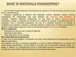
  • 7. The Figure shows three thin disk specimens placed over some printed matter. It is obvious that the optical properties of each of the three materials are different; the one on the left is transparent, whereas the disks in the center and on the right are, respectively, translucent and opaque. All of these specimens are of the same material, aluminum oxide, but the: Leftmost one is what we call a single crystal—that is, it is highly perfect—which gives rise to its transparency. The center one is composed of numerous and very small single crystals that are all connected; the boundaries between these small crystals scatter a portion of the light reflected from the printed page, which makes this material optically translucent. The specimen on the right is composed not only of many small, interconnected crystals, but also of a large number of very small pores or void spaces. These pores also effectively scatter the reflected light and render this material opaque. Thus, the structures of these three specimens are different in terms of crystal boundaries and pores, which affect the optical transmittance properties. Furthermore, each material was produced using a different processing technique.
  • 8. Crystalline Structure Of Metals The properties of some materials are directly related to their crystal structures. The crystalline structure of a material usually relates to the arrangement of its internal Components. Subatomic structure involves electrons within the individual atoms and interactions with their nuclei. Atomic structure involves arrangement of atoms in materials and defines interaction among atoms (interatomic bonding). Microscopic structure involves arrangement of small grains of material that can be identified by microscopy. Macroscopic structure relates to structural elements that may be viewed with the naked eye. Macroscopic structure Atomic level Subatomic level Microscopic structure
  • 9. Each atom consists of a very small nucleus composed of protons and neutrons, which is encircled by moving electrons. Both electrons and protons are electrically charged, the charge magnitude being 1.62*10^-19 C, which is negative in sign for electrons and positive for protons; neutrons are electrically neutral. Masses for these subatomic particles are infinitesimally small; protons and neutrons have approximately the same mass, 1.67*10^-27 kg, which is significantly larger than that of an electron, 9.11*10^-31 kg. The atomic mass of a specific atom may be expressed as the sum of the masses of protons and neutrons within the nucleus.
  • 10. Body-Centered Cubic Crystal Structure Face-Centered Cubic Crystal Structure Hexagonal Close-Packed Crystal Structure
  • 11. ATOMIC PACKING FACTOR For BCC APF 0.68 Volume of atoms in unit cell APF For FCC APF 0.74 Volume unit cell Total number of atom s in unit cell Volume of unit atoms For HCP APF ? Volume unit cell Show that the atomic packing factor for the BCC crystal structure is 0.68. Show that the atomic packing factor for the FCC crystal structure is 0.74. What is the atomic packing factor for the HCP crystal structure?. Show that for HCP the c/a ratio is 1.633 3 3 a2 Area of a Hexagon 2 Numerical Problems 1. Calculate the volume of an BCC unit cell in terms of the atomic radius R. 2. Calculate the volume of an FCC unit cell in terms of the atomic radius R. 3. Calculate the volume of an HCP unit cell in terms of the atomic radius R.
  • 12.
  • 13.
  • 14. Allotropy Allotropy is the ability of an element to exist in different structural forms while in the same state of matter. The allotropes depend on both the allotropy temperature and the external pressure. For example, the allotropes of carbon include diamond (where the carbon atoms are bonded together in a tetrahedral lattice arrangement), graphite (where the carbon atoms are bonded together in sheets of a hexagonal lattice). Graphite is the stable polymorph at ambient conditions, whereas diamond is formed at extremely high pressures. Also, pure iron has a BCC crystal structure at room temperature, which changes to FCC iron at 912◦ C
  • 15.
  • 16. Crystallographic Directions, and Planes Deformation under loading (slip) occurs on certain crystalline planes and in certain crystallographic directions. Before we can predict how materials fail, we need to know what modes of failure are more likely to occur. • It is often necessary to be able to specify certain directions and planes in crystals. • Many material properties and processes vary with direction in the crystal. • Directions and planes are described using three integers; Miller Indices Method of describing Miller indices for Directions • Draw vector, and find the coordinates of the head, h1,k1,l1 and the tail h2,k2,l2. • Subtract coordinates of tail from coordinates of head • Remove fractions by multiplying by smallest possible factor • Enclose in square brackets
  • 17. Draw the following direction vectors in cubic unit cells: (a) [100] and [110] (b) [112] (c) [110] (d) [321] (a) The position coordinates for the direction indices [100] and [110] direction are (1, 0, 0) and (1, 1, 0), respectively (Fig. a). (b) The position coordinates for the [112] direction are obtained by dividing the direction indices by 2 so that they will lie within the unit cube. Thus the position coordinates are (1/2,1/2,1) (Fig. b). (c) The position coordinates for the [Ī10] direction are (-1, 1, 0) (Fig. c). Note that the origin for the direction vector must be moved to the lower-left front corner of the cube. (d) The position coordinates for the[321] direction are obtained by first dividing all the indices by 3, the largest index. This gives -1,-2/3,-1/3 which are shown in Fig. d.
  • 18. Method of describing Miller indices for Planes The procedure for determining the Miller indices for a cubic crystal plane is as follows: 1. Choose a plane that does not pass through the origin at (0, 0, 0). 2. Determine the intercepts of the plane in terms of the crystallographic x, y, and z axes for a unit cube. These intercepts may be fractions. 3. Form the reciprocals of these intercepts. 4. Clear fractions and determine the smallest set of whole numbers that are in the same ratio as the intercepts. These whole numbers are the Miller indices of the crystallographic plane and are enclosed in parentheses without the use of commas. The notation (hkl) is used to indicate Miller indices in a general sense, where h, k, and l are the Miller indices of a cubic crystal plane for the x, y, and z axes, respectively. Draw the following crystallographic planes in cubic unit cells: (a) (101) (b) (110) (c) (221)
  • 19. Point defects: (a) vacancy, (b) interstitial atom, (c) small substitutional atom, (d) large substitutional atom, (e) Frenkel defect, and (f) Schottky defect.
  • 20. Vacancies: A vacancy is produced when an atom or an ion is missing from its normal site in the crystal structure. When atoms or ions are missing (i.e., when vacancies are present), the overall randomness or entropy of the material increases, which increases the thermodynamic stability of a crystalline material. All crystalline materials have vacancy defects. Vacancies are introduced into metals and alloys during solidification, at high temperatures, or as a consequence of radiation damage. Interstitial Defects: An interstitial defect is formed when an extra atom or ion is inserted into the crystal structure at a normally unoccupied position. Interstitial atoms such as hydrogen are often present as impurities, whereas carbon atoms are intentionally added to iron to produce steel. A substitutional defect is introduced when one atom or ion is replaced by a different type of atom or ion. A Frenkel defect is a vacancy-interstitial pair formed when an ion jumps from a normal lattice point to an interstitial site. A Schottky defect, is unique to ionic materials and is commonly found in many ceramic materials. When vacancies occur in an ionically bonded material, a stoichiometric number of anions and cations must be missing from regular atomic positions if electrical neutrality is to be preserved. For example, one Mg+2 vacancy and one O-2 vacancy in MgO constitute a Schottky pair.
  • 21. Iron ores are rocks and minerals from which metallic iron can be economically extracted. The ores are usually rich in iron oxides and vary in colour from dark grey, bright yellow, deep purple, to rusty red. The iron itself is usually found in the form of magnetite (Fe3O4), hematite (Fe2O3), goethite (FeO(OH)), limonite (FeO(OH)n(H2O)) or siderite (FeCO3). Smelting To convert it to metallic iron it must be smelted or sent through a direct reduction process to remove the oxygen. Oxygen-iron bonds are strong, and to remove the iron from the oxygen, a stronger elemental bond must be presented to attach to the oxygen. Carbon is used because the strength of a carbon-oxygen bond is greater than that of the iron-oxygen bond, at high temperatures. Thus, the iron ore must be powdered and mixed with coke, to be burnt in the smelting process.
  • 22. Iron Pure iron rarely exists outside of the laboratory. Iron is produced by reducing iron ore to pig iron through the use of a blast furnace. From pig iron many other types of iron and steel are produced by the addition or deletion of carbon and alloys. The following paragraphs discuss the different types of iron and steel that can be made from iron ore. PIG IRON.— Pig iron is composed of about 93% iron, from 3% to 5% carbon, and various amounts of other elements. Pig iron is comparatively weak and brittle; therefore, it has a limited use and approximately ninety percent produced is refined to produce steel. Cast-iron pipe and some fittings and valves are manufactured from pig iron. Carbon 3.0–4.5% Manganese 0.15–2.5% Phosphorus 0.1–2.0% Silicon 1.0–3.0% Sulphur 0.05–0.1% WROUGHT IRON.— Wrought iron is made from pig iron with some slag mixed in during manufacture. Almost pure iron, the presence of slag enables wrought iron to resist corrosion and oxidation. The chemical analyses of wrought iron and mild steel are just about the same. The difference comes from the properties controlled during the manufacturing process. Wrought iron can be gas and arc welded, machined, plated, and easily formed; however, it has a low hardness and a low-fatigue strength. CAST IRON.— Cast iron is any iron containing greater than 2% carbon alloy. Cast iron has a high compressive strength and good wear resistance; however, it lacks ductility, malleability, and impact strength.
  • 24. All of the phosphorus and most of the manganese will enter the molten iron. Oxides of silicon and sulphur compounds are partially reduced, and these elements also become part of the resulting metal. Other contaminant elements, such as calcium, magnesium, and aluminium, are collected in the limestone-based slag and are largely removed from the system. The resulting pig iron tends to have roughly the following composition: Carbon 3.0–4.5% Manganese 0.15–2.5% Phosphorus 0.1–2.0% Silicon 1.0–3.0% Sulphur 0.05–0.1%
  • 26. Modern Blast Furnace 1: Iron ore + Calcareous sinter 2: coke 3: conveyor belt 4: feeding opening, with a valve that prevents direct contact with the internal parts of the furnace 5: Layer of coke 6: Layers of sinter, iron oxide pellets, ore, 7: Hot air (around 1200°C) 8: Slag 9: Liquid pig iron 10: Mixers 11: Tap for pig iron 12: Dust cyclon for removing dust from exhaust gasses before burning them in 13 13: Air heater 14: Smoke outlet (can be redirected to carbon capture & storage (CCS) tank) 15: feed air for Cowper air heaters 16: Powdered coal 17: cokes oven 18: cokes bin 19: pipes for blast furnace gas
  • 27. PRODUCTION OF IRON Iron is the fourth most plentiful element in the earth’s crust, it is rarely found in the metallic state. Instead, it occurs in a variety of mineral compounds, known as ores, the most attractive of which are iron oxides coupled with companion impurities. To produce metallic iron, the ores are processed in a manner that breaks the iron–oxygen bonds. Ore, limestone, coke (carbon), and air are continuously introduced into specifically designed furnaces and molten metal is periodically withdrawn. The production of iron in a blast furnace is a continuous process. The furnace is heated constantly and is re-charged with raw materials from the top while it is being tapped from the bottom. Iron making in the furnace usually continues for about ten years before the furnace linings have to be renewed. Blast furnace is a furnace for smelting of iron from iron oxide ores (hematite, Fe2O3 or magnetite, Fe3O4). Coke, limestone and iron ore are poured in the top, which would normally burn only on the surface. The hot air blast to the furnace burns the coke and maintains the very high temperatures that are needed to reduce the ore to iron. The reaction between air and the fuel generates carbon monoxide. This gas reduces the iron oxide in the ore to iron. Fe2O3(s) + CO(g) Fe(s) + CO2(g)
  • 28. BLAST FURNACE CHEMISTRY FOR THE PRODUCTION OF IRON The significant reactions occurring within the Blast Furnace can be described as follows: 1. Iron is extracted from its ores by the chemical reduction of iron oxides with carbon in a furnace at a temperature of about 800 C - 1900 C. 2. Coke, the source of chemical energy in the blast furnace, is burnt both to release heat energy and to provide the main reducing agent: 3. Calcium oxide, formed by thermal decomposition of limestone, reacts with the silicon oxide present in sand, a major impurity in iron ores, to form slag (which is less dense than molten iron). Overall, the chemical processes can be summarized by these equations: At 500o C 3Fe2O3 +CO -> 2Fe3O4 + CO2 Fe2O3 +CO -> 2FeO + CO2 At 850o C Fe3O4 +CO -> 3FeO + CO2 At 1000o C FeO +CO -> Fe + CO2 At 1300 oC CO2 + C -> 2CO At 1900o C C+ O2 -> CO2 FeO +C -> Fe + CO
  • 29. PRODUCTION OF STEEL When iron is smelted from its ore by commercial processes, it contains more carbon than is desirable. In order to convert the pig iron into steel, it must be melted and reprocessed to reduce the carbon to the correct amount, at which point other elements can be added. This liquid is then continuously cast into long slabs or cast into ingots. Approximately 96% of steel is continuously cast, while only 4% is produced as cast steel ingots. The ingots are then heated in a soaking pit and hot rolled into slabs, blooms, or billets. Slabs are hot or cold rolled into sheet metal or plates. Billets are hot or cold rolled into bars, rods, and wire. Blooms are hot or cold rolled into structural steel, such as I-beams and rails. In modern foundries these processes often occur in one assembly line, with ore coming in and finished steel coming out. Sometimes after steel’s final rolling it is heat treated for strength, however this is relatively rare. Iron as obtained from blast furnace contains from 3-4% of Carbon, and variable amount of silicon, manganese sulphur and phosphorus. 1. Dead mild steel — up to 0.15% carbon 2. Low carbon or mild steel — 0.15% to 0.45% carbon 3. Medium carbon steel — 0.45% to 0.8% carbon 4. High carbon steel — 0.8% to 1.5% carbon
  • 30. STEEL MAKING PROCESSES  Bessemer Process  Crucible Process  Open Hearth Process  Electric Process (Arc, Induction)  Duplex Process  Linz Donnawitz Process  Kaldo Process  Modern Process
  • 31. Bessemer Process Bessemer process was invented in1875 by Thomas Gilchrest. In Bessemer process the molten pig iron from blast furnace is poured into converter. The converter is made of steel plates lined inside with refractory material. In the bottom of converter vessels, a no of holes are introduced through which air is blown at a pressure of 200-250KN/m2. Based on full capacity, the converter is charged with 100-150 ton, and this charge is carried out from 10 to 15 ton at different time intervals. Their first oxidizes silicon, and manganese which together with iron oxide rise to the top from slag. During this air blowing process the carbon begins to burn and blowing continued, until 0.25% of carbon is eliminated. In Bessemer process acids are used to burn and eliminated silicon and phosphorus. The finished steel is then poured into ladles and from ladle it is poured into ingot moulds for subsequently rolling and forging process.
  • 32. Crucible Process In Crucible process wrought iron together with a small amount of pig iron, necessary alloying metals and slagging materials are placed in a clay or clay-graphite crucible, covered with an old crucible bottom and melted in a gas or coke-fired furnace. After the charge is entirely molten, with sufficient time allowed for the gases and impurities to rise to the surface, the Crucible is withdrawn, the slag removed with a cold iron bar, and the resulting steel poured into a small ingot which is subsequently forged to the desire shape. There are three types of Crucible Furnaces: (a) lift-out crucible, (b) stationary pot, from which molten metal must be ladled, and (c) tilting-pot furnace
  • 33. Open Hearth Process The open-hearth furnace is rectangular and rather low, holding from 15 to 200 ton of metal in a saucer-like shallow pool. It is heated either by producer gas, oil, tar, mixed blast furnace and coke oven gas, pitch, mixture of creosote and pitch and heavy fuel oil. Flames come from first one end and then the other. Waste gases pass through regenerators. The furnace is charged with ore and limestone. The lime stone begins to decompose in carbon di-oxide and calcium oxide. A. gas and air enter B. pre-heated chamber C. molten pig iron D. hearth E. heating chamber F. gas and air exit.
  • 34. Electric Furnace An Electric Arc Furnace (EAF) is a furnace that heats charged material by means of an electric arc. An electric arc furnace used for steelmaking consists of a refractory-lined vessel, usually water-cooled in larger sizes, covered with a retractable roof, and through which one or more graphite electrodes enter the furnace. Arc furnaces differ from induction furnaces in that the charge material is directly exposed to an electric arc, and the current in the furnace terminals passes through the charged material. An induction furnace is an electrical furnace in which the heat is applied by induction heating of metal. The advantage of the induction furnace is a clean, energy-efficient and well-controllable melting process compared to most other means of metal melting. The one major drawback to Electric furnace usage in a foundry is the lack of refining capacity; charge materials must be clean of oxidation products and of a known composition and some alloying elements may be lost due to oxidation. Induction furnace is based on the principle of heating by induced currents. If a conductor is placed within a coil through which an alternating current is flowing, a current is induced in the conductor. By the normal la of electricity this conductor is heated. The magnitude of the current generated depends on: _the physical dimensions of the coil; _the resistivity of the conductor and _the frequency of the current.
  • 35. Linz-Donawitz (LD) or Basic oxygen steel making (BOS) Process The basic oxygen steel-making process is as follows: 1. Molten pig iron from a blast furnace is poured into a large refractory-lined container called a ladle. Besides the BOS vessel is one-fifth filled with steel scrap. 2. The metal in the ladle is sent directly for basic oxygen steelmaking or to a pre- treatment stage. Pre-treatment of the blast furnace metal is used to reduce the refining load of sulphur, silicon, and phosphorus. In desulfurising pre-treatment, several hundred kilograms of powdered magnesium are added. Sulphur impurities are reduced to magnesium sulphide in a violent exothermic reaction. The sulphide is then raked off. Similar pre-treatment is possible for desiliconisation and dephosphorisation using lime as reagents. The decision to pretreat depends on the quality of the blast furnace metal and the required final quality of the BOS steel. 3. Fluxes (lime or dolomite) are fed into the vessel to form slag, which absorbs impurities of the steelmaking process. During blowing the metal in the vessel forms an emulsion with the slag, facilitating the refining process.
  • 36. Kaldo Process: The Kaldo process, is a modification of LD process. It was originally developed in Sweden by Prof. Kalling. This process is based on the advantage of evolution of heat by high phosphorus(2%) pig iron to as low as 0.02% P. The converter in Kaldo Process is inclined at 150 to 200 with the horizontal, and rotated at a speed of 25-30 r.p.m. The oxygen lance is introduced through the open end of the vessel, which also acts as the outlet for the exhaust gases. The use of oxygen allows simultaneous removal of carbon and phosphorus from the (p 1.85%) pig iron. The rotation of the converter ensures better slag-metal reaction.
  • 37. MODERN STEEL MAKING PROCESS Vacuum Induction Melting process: This process is similar to the induction melting process with suitable arrangement for creating a vacuum. This process is used for making super alloys containing nickel and cobalt as base metals. It is very suitable process for further remelting for investment casting. Due to vacuum prevailing in the chamber , non-metallic inclusions can be minimized and composition of chemically reactive elements like titanium , boron and aluminium can be controlled accurately. New alloys of steel possessing greater uniformly and reproducibility of properties accompanied by greater strength, creep resistance, etc can be produced. Consumable Electrical Vacuum Arc Melting Process: It is direct arc steel melting process in which the electrode is consumed during melting. This process was originally used for titanium. Since this process eliminates hydrogen, oxygen, and volatile materials, it is extensively used for special-purpose steels, as in moving parts of aircraft engines, due to need of high strength, uniformity of properties, greater toughness and freedom from tramp and volatile elements. Electric slag refining (ESR) Process: This process is commonly known as ESR. It is a larger form of the original welding process . It is the electrical resistance heating process that remelts the preformed electrode into a water-cooled crucible. Due to resistance to flow of current, the metal melts and drops onto the crucible through a layer of slag around the ingot. The process is used for making high alloy, high quality steels for obtaining superior properties normally not achieved in conventional processing. For example, ultra high strength weldable steel.
  • 38. EQUILIBRIUM PHASE DIAGRAM A phase may be defined as a homogeneous portion of a system that has uniform physical and chemical characteristics. One-component or Unary Phase Diagram (P-T Diagram) An equilibrium phase diagram is a graphic mapping of the natural tendencies of a material or a material system, assuming that equilibrium has been attained for all possible conditions. There are three primary variables to be considered: temperature, pressure, and composition. The simplest phase diagram is a pressure–temperature (P–T) diagram for a fixed-composition material. Areas of the diagram are assigned to the various phases, with the boundaries indicating the equilibrium conditions of transition. P–T phase diagrams are rarely used for engineering applications. Most engineering processes are conducted at atmospheric pressure, and variations are more likely to occur in temperature and composition.
  • 39. COMPLETE SOLUBILITY IN BOTH LIQUID AND SOLID STATES The upper line is the liquidus line, the lowest temperature for which the material is 100% liquid. Above the liquidus, the two materials form a uniform-chemistry liquid solution. The lower line, denoting the highest temperature at which the material is completely solid, is known as a solidus line. Below the solidus, the materials form a solid-state solution in which the two types of atoms are uniformly distributed throughout a single crystalline lattice. Between the liquidus and solidus is a freezing range, a two-phase region where liquid and solid solutions coexist. Binary Phase Diagram CONDITIONS FOR UNLIMITED SOLID SOLUBILITY 1. Size factor: The atoms or ions must be of similar size, with no more than a 15% difference in atomic radius. 2. Crystal structure: The materials must have the same crystal structure; otherwise, there is some point at which a transition occurs from one phase to a second phase with a different structure. 3. Valence: The ions must have the same valence; otherwise, the valence electron difference encourages the formation of compounds rather than solutions.
  • 40.
  • 41. INTERPRETATION OF PHASE DIAGRAMS In a phase diagram, for each point of temperature and composition, following three pieces of information can be obtained: 1. The phases present: The stable phases can be determined by simply locating the point of consideration on the temperature–composition mapping and identifying the region of the diagram in which the point appears. 2. The composition of each phase: If the point lies in a two-phase region, a tie-line must be constructed. A tie-line is simply an isothermal (constant-temperature) line drawn through the point of consideration, terminating at the boundaries of the single phase regions on either side. The compositions where the tie-line intersects the neighbouring single-phase regions will be the compositions of those respective phases in the two- phase mixture. 2. Amount of each phase: 1. The tie line is constructed across the two-phase region at the temperature of the alloy. 2. The overall alloy composition is located on the tie line. 3. The fraction of one phase is computed by taking the length of tie line from the overall alloy composition to the phase boundary for the other phase, and dividing by the total tie line length. 4. The fraction of the other phase is determined in the same manner.
  • 42.
  • 43. PARTIAL SOLID SOLUBILITY Many materials do not exhibit complete solubility in the solid state. Each is often soluble in the other up to a certain limit or saturation point, which varies with temperature. INSOLUBILITY If one or both of the components are totally insoluble in the other, the diagrams will also reflect this phenomenon. The following Figure illustrates the case where component A is completely insoluble in component B in both the liquid and solid states.
  • 44. The three-phase reaction that occurs upon cooling through 183°C can be written as: The lead–tin phase diagram
  • 45. Figure given below summarizes the various forms of three-phase reactions that may occur in engineering systems, along with the generic description of the reaction shown below the figures. These include the eutectic, peritectic, monotectic, and syntectic reactions, where the suffix -ic denotes that at least one of the three phases in the reaction is a liquid. If the same prefix appears with an -oid suffix, the reaction is of a similar form but all phases involved are solids. Two such reactions are the eutectoid and the peritectoid. The separation eutectoid produces an extremely fine two-phase mixture, and the combination peritectoid reaction is very sluggish since all of the chemistry changes must occur within (usually crystalline) solids. If components A and B form a compound, and the compound cannot tolerate any deviation from its fixed atomic ratio, the product is known as a stoichiometric intermetallic compound and it appears as a single vertical line in the diagram
  • 46.
  • 47. IRON–CARBON PHASE DIAGRAM Steel, composed primarily of iron and carbon, is the most important of the engineering metals. For this reason, the iron–carbon equilibrium diagram assumes special importance. We normally are not interested in the carbon-rich end of the Fe-C phase diagram and this is why the full iron–carbon (Fe-C) diagram is not normally encountered, but we examine the Fe-Fe3C diagram as part of the Fe-C binary phase Diagram. In the Figure, stoichiometric intermetallic compound, Fe-Fe3C, is used to terminate the carbon range at 6.67 wt% carbon. Immediately after solidification, iron forms a BCC structure called δ-ferrite. On further cooling, the iron transforms to a FCC structure called γ, or austenite. Finally, iron transforms back to the BCC structure at lower temperatures; this structure is called α, or ferrite. Both of the ferrites (α and δ) and the austenite are solid solutions of interstitial carbon atoms in iron.
  • 48. The fourth single phase is the stoichiometric intermetallic compound which goes by the name cementite, or iron–carbide. Like most intermetallics, it is quite hard and brittle, and care should be exercised in controlling the structures in which it occurs. Alloys with excessive amounts of cementite, or cementite in undesirable form, tend to have brittle characteristics. Because cementite dissociates prior to melting, its exact melting point is unknown, and the liquidus line remains undetermined in the high-carbon region of the diagram.