Abhishek and tarachand stone columns an over view
•Télécharger en tant que DOC, PDF•
4 j'aime•1,849 vues

This document provides an overview of stone columns, which are columns of compacted aggregate installed in soft soils to improve their load-bearing capacity and reduce settlement. Stone columns function by transferring load to the stiffer column material, allowing drainage of pore water pressures. They are installed using ramming or vibro-replacement techniques. Failure typically occurs through bulging of the column into the surrounding soil. A case study demonstrates that a highway embankment treated with stone columns at 2m spacing experienced 25% less settlement than untreated ground.

Recommandé
Contenu connexe
Tendances
Tendances (20)
En vedette
En vedette (20)
Similaire à Abhishek and tarachand stone columns an over view
Similaire à Abhishek and tarachand stone columns an over view (20)
Dernier
Dernier (20)
Abhishek and tarachand stone columns an over view
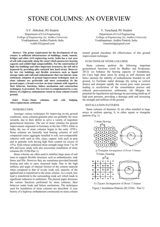
- 1. STONE COLUMNS: AN OVERVIEW S.V. Abhishek, PG Student V. Tarachand, PG Student Department of Civil Engineering College of Engineering (A), Andhra University Visakhapatnam, Andhra Pradesh, India svabhi.92@gmail.com Department of Civil Engineering College of Engineering (A), Andhra University Visakhapatnam, Andhra Pradesh, India vtarachandg@gmail.com Abstract—The prime requirement for the development of any country is sufficient infrastructure of buildings, roads, tunnels, bridges and other civil engineering works. India has a vast area of soft soils (especially along the coast) which possess low bearing capacity and exhibit high compressibility. For the construction of high rise buildings and other important structures, the soft soil is bypassed by providing piles socketed into hard strata. However for low rise buildings and flexible structures such as liquid storage tanks and rail/road embankments that can tolerate some settlement, adoption of ground improvement techniques such as stone columns are preferable and more economical. In the present paper, a broad overview on stone columns with regard to their behavior, functions, failure mechanism and construction techniques, is presented. The overview is complemented by a case history of a highway embankment raised on stone column treated ground. Index Terms—Stone columns, vibro-replacement, settlement unit cell, bulging, INTRODUCTION Amongst various techniques for improving in-situ ground conditions, stone columns/granular piles are probably the most versatile, due to their ability to serve a variety of important geotechnical functions. The use of stone columns for ground improvement originated in Germany in the late 1950’s while in India, the use of stone columns began in the early 1970’s. Stone columns are basically load bearing columns of well compacted coarse aggregate installed in soft, non-compactable cohesive soils such as silts, clays; organic soils such as peat and in granular soils having high fines content (in excess of 15%). Soils whose undrained shear strength range from 7 to 50 kPa and loose sandy soils also necessitate installation of stone columns (IS:15284-Part 1). Stone columns are often used to stabilize large areas of soil mass to support flexible structures such as embankments, tank farms and fills. However they are sometimes provided beneath footing and rafts to carry structural loads. Due to the high stiffness and angle of internal friction of the column material when compared to that of in-situ weak soil, majority of the applied load is transferred to the stone column. As a result, less load is transferred to the surrounding weak soil which leads to significant reduction in settlement. The present paper discusses the various functions performed by stone columns, their behavior under loads and failure mechanism. The techniques used for installation of stone columns are described. A case history of a highway embankment constructed on stone column treated ground elucidates the effectiveness of this ground improvement technique. FUNCTIONS OF STONE COLUMNS Stone columns perform the following important geotechnical functions (cited by Madhav and Sivakumar, 2012): (a) Enhance the bearing capacity of foundations, (b) Carry high shear stress by acting as stiff elements and hence increase the stability of embankments founded on soft ground, (c) Facilitate radial drainage (by acting as vertical drains) and dissipate rapidly the excess pore water pressure leading to acceleration of the consolidation process and reduced post-construction settlements, (d) Mitigate the potential for liquefaction and damage by preventing build up of high pore pressure, providing a drainage path and increasing the strength and stiffness of the ground. INSTALLATION PATTERNS Stone columns of diameter, D, are often installed in large arrays at uniform spacing, S, in either square or triangular patterns (Fig. 1). Figure 1 Installation Patterns (IS:15284 – Part 1)
- 2. For such cases, a unit cell consisting of stone columns surrounded by in-situ soil in the zone of influence can be considered as representative of the treated area. In the unit cell approach, the tributary area of soil surrounding each stone column (in the form of hexagon and square for triangular and square arrangement respectively) is closely approximated by an equivalent circle of diameter, De. For an equilateral triangular and square arrangement of stone columns, the equivalent circle has an effective diameter of 1.05S and 1.13S respectively, where ‘S’ is the centre to centre spacing of stone columns (generally ranges from 2 to 3 m). The equilateral triangular pattern gives the densest packing of stone columns in a given area and is thus preferable. The resulting cylinder of composite ground with diameter, De, enclosing the tributary soil and one stone column is known as the unit cell. (Hughes and Withers, 1974; Hughes et al. 1976). However, when stone columns are installed in extremely soft soils having undrained shear strength less than 7 kPa, the radial confinement/restraint offered by the surrounding soil is inadequate, resulting in excessive lateral displacement of stone into the surrounding soil. In such circumstances, the load carrying capacity of the stone column can be improved by encasing the column in a suitable geosynthetic. Fig. 3 depicts the load carrying mechanism of a single, isolated stone column in compression. The length of stone column over which bulging takes place is known as critical length (about 4 times the diameter of the column). FAILURE MECHANISMS Stone columns are often constructed through soft soils fully penetrating to an end bearing stratum. However, they may be constructed as floating piles; the tips ending within the soft layer but at depths where the strength of soil is adequate. Stone columns may fail individually or as a group. The failure mechanisms for a single, isolated stone column in compression are illustrated in Fig. 2 indicating respectively, the possible failures as a) bulging, b) shear failure and c) sliding/punching. Figure 3 Pre-bulging failure mode of a single stone column Apart from bulging, stone columns derive their load carrying capacity through surface resistance or frictional resistance developed between the column material and surrounding weak soil acting upwards within the critical length, and also from the passive resistance mobilized by the column material. The portion of the stone column below the critical length does not participate in load transfer but functions akin to a vertical drain and accelerates the consolidation of the surrounding soft soil. Figure 2 Failure mechanisms of a single stone column in a homogeneous soft layer (IS:15284 – Part 1) For single, isolated stone columns, the most probable failure mechanisms are bulging or punching. Punching failure mechanism controls the ultimate load for short columns resting on soft to medium stiff bearing layer (the tip of the column is floating in the soft soil) while bulging failure is most likely for a long stone column irrespective of end bearing or floating (Madhav et al. 1994). A long stone column is one whose length is greater than its critical length (about 4 times the diameter of the column). Practically since most stone columns are installed upto depths of 10-15 m preferably into stiff end bearing stratum, lateral bulging of the column into the surrounding weak soil is the pre-dominant load transfer mechanism, i.e., the stone columns derive their load carrying capacity from the lateral earth pressure against bulging from the surrounding soil INSTALLATION TECHNIQUES The common techniques employed for installation of stone columns are 1) Rammed Stone Column Technique and 2) Vibro-Replacement. 1) Rammed Stone Column Technique: In this technique, a borehole is created by using a bailer. Stone chips are tipped into the borehole and are compacted by using a rammer (Fig. 4). Alternatively, a closed end pipe mandrel can be driven to the desired depth. The tip valve is opened to discharge the stone chips delivered through the pipe. The mandrel is withdrawn until the valve can be closed and the same is used to ram against the stone chips to expand and densify. A boring of 400-500 mm diameter generates a column of 700-900 mm in diameter. The fill material should vary in particle size from about 5-100 mm with not more than 15% material finer than 5 mm.
- 3. around the vibrator from the ground surface. The stone is compacted and pressed into the surrounding soil by alternating steps of retraction and re-penetration of the vibrator. Gradually, in stages, by pouring the stone from the ground surface with the help of a wheel loader and compaction of the stone by vibrator, a stone column is constructed upto the platform level. A schematic of the stone column installation by the wet top-feed method is shown in Fig. 5. Figure 4 Rammed stone column by bailer and chisel technique 2) Vibro-Replacement: The technique of vibro- replacement employs a deep vibro poker (depth vibrator) which ensures construction of properly compacted stone columns of required diameter and depth as well as densification of the surrounding soil between the columns. Vibro-Replacement is further classified into two types depending on the mode of penetration of the vibrator and feeding of stone into the borehole as, (a) Wet Top-Feed Method and (b) Dry Bottom-Feed Method (b) Dry Bottom-Feed Method In this method, the vibrator supported by a purpose built base machine called “Vibrocat”, displaces the surrounding soil and penetrates to the required treatment depth aided by the action of vibrations, compressed air and pull down facility from the winch. Initially, the vibrocat positions the vibrator over the required location of the compaction point and stabilizes itself using hydraulic supports. A wheel loader then fills the bucket with stones of size typically ranging from 20 mm to 40 mm. The bucket is lifted and its contents are emptied into the air chamber provided with an air lock. Once the air lock is closed the aggregate is supplied to the tip of the vibrator through a special stone tube with the assistance of pressurized air. The vibrator penetrates into the ground and upon reaching the design depth, it is retracted by about 0.5 to 1.0 m, causing the aggregate in the pressurized stone tube to exit and fill the cavity so created. The vibrator then re-penetrates into the in-filled space resulting in effective compaction of the aggregates into surrounding soil. (a) Wet Top-Feed Method In this method, the depth vibrator hung from a crawler crane, penetrates to the required treatment depth under its own self weight (about 17.8 kN) aided by high pressure water jets which are an integral part of the vibrator. The high pressure water jets create a momentary quick condition ahead of the vibrator tip by washing out the fine soil particles and thus permit penetration of the vibrator into the ground. Figure 6 Schematic of Dry Bottom-Feed Method (Courtesy of Keller Group) Figure 5 Schematic of Wet Top-Feed Method (Courtesy of Keller Group) Upon reaching the required depth, stones of size typically ranging from 40 mm to 75 mm are tipped into the annular gap The stone column is constructed in alternating steps of retraction and re-penetration until the aggregates in the stone tube are exhausted. Thereafter, another charge of aggregate is loaded into the stone tube. In this way the stone column construction process continuous upto the platform level. After completion of installation of all the stone columns, the surface is leveled and if necessary compacted with a vibratory roller. A schematic of the installation procedure is depicted in Fig .6.
- 4. CASE HISTORY Oh et al. (2007) presented a case history of a highway embankment constructed over soft estuarine clay with high sensitivity and low undrained shear strength. The embankment was divided into three sections, section 1 with no stone columns, section 2 with stone columns at 2 m spacing and section 3 with stone column at 3 m spacing. The embankment was constructed in two stages. Each stage consisted of a fill height of 2 m and thus the final height of the embankment was 4 m. The side slopes of the embankment were 1(V):2(H) and the base width was 20 m. The diameter and length of the stone columns are 1 m and 14 m respectively. The columns were installed in square pattern using the vibro-replacement technique. Fig. 7 depicts the geometry of the embankment over stone column treated ground while Fig. 8 shows the variation of the liquid limit (wL), plastic limit (wP), natural moisture content (wn) and undrained shear strength (su) of the soft clay with depth. (from Oh et al. 2007) The soil profile at the site consisted of 14 m thick deposit of very soft to soft estuarine clay overlying moderately dense to dense sandy sediment stratum. The natural moisture content of the soft clay varied from 60-100% and was greater than the liquid limit. The undrained shear strength of the soft clay was low and varied from 5-20 kPa. The compressibility of the soft clay ranged from 0.5-3.5 m2/MN while the coefficient of consolidation varied from 0.2 to 0.3 m2/year. Settlement gauges were installed at various locations in the embankment to monitor the deformations of the underlying soft clay. Figs. 9 (a), (b) and (c) show the measured settlement profiles corresponding to the embankment on untreated soft clay, embankment with stone columns at 3 m and 2 m spacing respectively, at different monitoring periods. It can be observed that the settlement of the embankment increased with time for both untreated as well as stone column treated case. The maximum measured post-construction settlements were about 520 mm, 495 mm and 390 mm for the untreated, 3 m spaced and 2 m spaced stone columns respectively. The reduction in settlement was about 5% and 25% of the settlement for the untreated case, corresponding to the 3 m and 2 m spaced stone columns, respectively. Figure 7 Geometry of embankment over stone column treated ground, all dimensions in m (after Oh et al. 2007) (a) Untreated soft clay Figure 8 Variation of wL, wp, wn and su with depth
- 5. (b) Stone columns at 3 m spacing well as seismic conditions. The case history presented, compares the response between an untreated embankment and embankment treated with stone columns installed at 2 m and 3 m spacing over soft estuarine clay. The embankment treated with stone columns spaced at 2 m centre to centre experienced the least settlement when compared to the other cases. REFERENCES (c) Stone columns at 2 m spacing Figure 9 Measured Settlement Profiles (from Oh et al. 2007) CONCLUSIONS Stone columns are one of the most versatile techniques for engineering the ground. They can be installed to improve a variety of ground conditions through several variants of the technique such as rammed stone columns and vibro-replacement (wet top-feed and dry bottom-feed methods). The in-situ ground is improved by reinforcement, densification and drainage functions performed by the stone columns. Further, they are equally effective under normal as [1] Hughes, J.M.O. and Withers, N.J. (1974) “Reinforcing of Soft Cohesive Soils with Stones Columns”, Ground Engineering, Vol. 7, No.3, pp. 42-49. [2] Hughes, J.M.O., Withers, N.J. and Greenwood, D.A. (1976) “A Field Trail of Reinforcing Effect of Stone Column in Soil”, Proceedings of Ground Treatment by Deep Compaction, Institution of Civil Engineers, pp. 32-44. [3] IS:15284 – Part 1 (2003) “Design and Construction for Ground Improvement-Guidelines for Stone Columns”, Bureau of Indian Standards, New Delhi, India. [4] Madhav, M.R., Alamgir, M. and Miura, M. (1994) “Improving Granular Column Capacity By Geogrid Reinforcement”, Proceedings of 5th International Conference on Geotextiles, Geomembranes and Related Products, Singapore, pp. 351-356. [5] Madhav, M.R. and Sivakumar, V. (2012) “Perspectives in Granular/Stone Columns Engineered Ground”, Proceedings of the International Conference on Ground Improvement and Ground Control”, Australia, pp. 621-628. [6] Oh, E.Y., Balasubhramaniam, A.S., Sorarak, C., Bolton, N., Chai, G.W.K., Huang, M. and Braund, M. (2007) “Behaviour of a Highway Embankment on Stone Column Provided Estuarine Clay”, Proceedings of 16th South East Asian Geotechnical Conference, Kaula Lumpur, Vol. 1, pp. 567-572.
- 6. (b) Stone columns at 3 m spacing well as seismic conditions. The case history presented, compares the response between an untreated embankment and embankment treated with stone columns installed at 2 m and 3 m spacing over soft estuarine clay. The embankment treated with stone columns spaced at 2 m centre to centre experienced the least settlement when compared to the other cases. REFERENCES (c) Stone columns at 2 m spacing Figure 9 Measured Settlement Profiles (from Oh et al. 2007) CONCLUSIONS Stone columns are one of the most versatile techniques for engineering the ground. They can be installed to improve a variety of ground conditions through several variants of the technique such as rammed stone columns and vibro-replacement (wet top-feed and dry bottom-feed methods). The in-situ ground is improved by reinforcement, densification and drainage functions performed by the stone columns. Further, they are equally effective under normal as [1] Hughes, J.M.O. and Withers, N.J. (1974) “Reinforcing of Soft Cohesive Soils with Stones Columns”, Ground Engineering, Vol. 7, No.3, pp. 42-49. [2] Hughes, J.M.O., Withers, N.J. and Greenwood, D.A. (1976) “A Field Trail of Reinforcing Effect of Stone Column in Soil”, Proceedings of Ground Treatment by Deep Compaction, Institution of Civil Engineers, pp. 32-44. [3] IS:15284 – Part 1 (2003) “Design and Construction for Ground Improvement-Guidelines for Stone Columns”, Bureau of Indian Standards, New Delhi, India. [4] Madhav, M.R., Alamgir, M. and Miura, M. (1994) “Improving Granular Column Capacity By Geogrid Reinforcement”, Proceedings of 5th International Conference on Geotextiles, Geomembranes and Related Products, Singapore, pp. 351-356. [5] Madhav, M.R. and Sivakumar, V. (2012) “Perspectives in Granular/Stone Columns Engineered Ground”, Proceedings of the International Conference on Ground Improvement and Ground Control”, Australia, pp. 621-628. [6] Oh, E.Y., Balasubhramaniam, A.S., Sorarak, C., Bolton, N., Chai, G.W.K., Huang, M. and Braund, M. (2007) “Behaviour of a Highway Embankment on Stone Column Provided Estuarine Clay”, Proceedings of 16th South East Asian Geotechnical Conference, Kaula Lumpur, Vol. 1, pp. 567-572.