Axa Assurance Maroc - Insurer Innovation Award 2024
Itron cf echo ii ultrasonic heat meter brochure - english
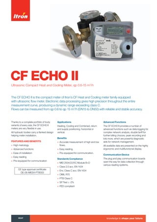
1. CF ECHO IIUltrasonic Compact Heat and Cooling Meter, qp 0.6-15 m3
/h
Thanks to a complete portfolio of body
variants of every size, the CF ECHO II
meters are very flexible in use.
All hydraulic bodies carry a flanked design
helping meter installation.
featuRes anD Benefits
» High metrology
» Advanced functions
» Ease of installation
» Easy reading
» Pre-equipped for communication
applications
Heating, Cooling and Combined, return
and supply positioning, horizontal or
vertical.
Benefits
» Accurate measurement of high and low
flows,
» Easy reading,
» Pre-equipped for communication.
standards compliance
» MID 2004/22/EC Module B+D
» Class 2.0 acc. EN 1434
» Env. Class C acc. EN 1434
» OIML R75
» PTB Class C
» SP Test ≤ -2%
» PED compliant
advanced functions
The CF ECHO II provides a number of
advanced functions such as data-logging for
complex network analysis, double tariff for
further billing choices, peak recording and
lots more, which are powerful diagnostic
aids for network management.
All available data are presented on the highly
ergonomic and multifunctional display.
communication Device
The plug and play communication boards
open the way for data collection through
various reading systems.
CE type approval certificate:
DE-06-MI004-PTB002
The CF ECHO II is the compact meter of Itron’s CF Heat and Cooling meter family equipped
with ultrasonic flow meter. Electronic data processing gives high precision throughout the entire
measurement curve, producing a dynamic range exceeding class C.
Flows can be measured from qp 0.6 to qp 15 m3
/h (DN15 to DN50) with reliable and stable accuracy.
heat knowledge to shape your future
Tel: +44 (0)191 490 1547
Fax: +44 (0)191 477 5371
Email: northernsales@thorneandderrick.co.uk
Website: www.heattracing.co.uk
www.thorneanderrick.co.uk
2. Multifunctional Display
The multifunctional display facilitates easy
reading, providing fast and clear access
to the most important billing data. The
display enables the diagnosis of failures
alarms form a single glance.
head loss
The LCD has a long life time and through
a push button you get easily access to
each level of data.
1 2 3 4 5 6
7
8
910111213
14
1 Alarm Icon 6 Loop Indicator 11 Elapsed Time Indicator
2 Dirty Warning 7 Units 12 Thresholds
3 Temperatures 8 Decimal Indication 13 External Water Meters
4 Flow Indicator 9 Pulse Input Value 14 Main Digits
5 Date & Time Digits 10 Peaks
100
1 000
10
1
10 100 1 000 10 000 100 000
mbar
L/h
qp0.6
qp1.5
qp10
qp15
qp2.5
qp3.5
qp6.0
100
1 000
10
1
10 100 1 000 10 000 100 000
mbar
L/h
qp0.6
qp1.5
qp10
qp15
qp2.5
qp3.5
qp6.0
Loop 1
Billing Data
Energy
Cooling energy*
Volume
LCD test
External water meter 1 + 2*
*optional
Loop 2
Additional Information
Flow rate
Power
Supply temperature
Return temperature
Temperature difference
Operating time
Power peak date + time*
Flow peak date + time*
Temperature peak date + time*
Time in alarm
Temperature alarm
Flow alarm
Overflow alarm
Power supply alarm
Current time + date*
M-Bus primary address
M-Bus secondary address
M-Bus baud rate
Pulse value water meter 1 + 2*
*optional
Loop 3
Fixed Date Reading
Fixed date energy 1...24
Fixed date cooling energy 1...24*
Fixed date volume 1...24
Fixed date water meter 1 + 2 1...24*
Software version
*optional
3. Technical Characteristics
Nominal Flow Diameter Max flow Min flow Start flow Body Pipe Nominal Permanent Accidential
Qp DN Qs Qi Qstart length Connection Pressure max. temp. max. temp.
m3
/h mm m3
/h L/h L/h mm bar °C °C
0.6 15 1.2 6 1.2 110 G 3/4 B 16/25 130 150
20 1.2 6 1.2 130 G 1 B 16/25 130 150
20 1.2 6 1.2 190 G 1 B/flanges 16/25 130 150
1.5 15 3 15 3 110 G 3/4 B 16/25 130 150
20 3 15 3 130 G 1 B 16/25 130 150
20 3 15 3 190 G 1 B/flanges 16/25 130 150
2.5 20 5 25 5 130 G 1 B 16/25 130 150
20 5 25 5 190 G 1 B/flanges 16/25 130 150
25 5 25 5 260 G 1 1/4 B 16/25 130 150
3.5 25 7 35 7 150 G 1 1/4 B 16/25 130 150
25 7 35 7 260 G 1 1/4 B/flanges 16/25 130 150
40 7 35 7 300 Flanges 25 130 150
6 25 12 60 12 150 G 1 1/4 B 16/25 130 150
25 12 60 12 260 G 1 1/4 B/flanges 16/25 130 150
32 12 60 12 260 G 1 1/2 B 16/25 130 150
40 12 60 12 300 Flanges 25 130 150
50 12 60 12 270 Flanges 25 130 150
10 40 20 100 20 200 G2 B 16/25 130 150
40 20 100 20 250 Flanges 25 130 150
40 20 100 20 300 G 2 B/flanges 16/25 130 150
50 20 100 20 270 Flanges 25 130 150
15 50 30 150 30 250 Flanges 25 130 150
50 30 150 30 270 Flanges 25 130 150
CF ECHO II Energy Calculator
Temperature range 0 ... 180°C
Temperature difference 3 ... 160 K
Temperature sensor type Pt100 or Pt500, 2 wires
Temperature sensor (Qp 0.6 to 2.5 m3
/h) Direct immersion or pocket type probes integrated in
the flow meter body
Cable length to flow meter From 0.4 to 10 m (Typical 1.5, 3 m)
Back-up memory EEPROM
Display LCD - 7 digits
Optical interface EN 60870-5 / M-Bus protocol
Power supply (optional) 6 or 12 year Lithium battery,
230V main power supply or power supply by M-Bus
CF ECHO II Testing Pulse Value (Qp) 0.6 1.5 2.5 3.5 6 10 15
cm3
/impuls 5 10 20 25 50 100 100