Beginners Guide to TikTok for Search - Rachel Pearson - We are Tilt __ Bright...
Dimensioning of the screw jack
1. 21
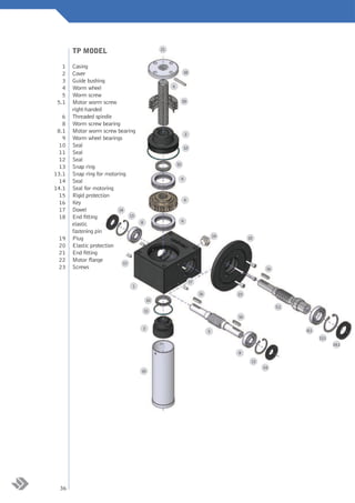
TP MODEL
1 Casing
2 Cover 18
3 Guide bushing
6
4 Worm wheel
5 Worm screw
5.1 Motor worm screw 20
right-handed
6 Threaded spindle
8 Worm screw bearing
8.1 Motor worm screw bearing 2
9 Worm wheel bearings
10 Seal 12
11 Seal
12 Seal
10
13 Snap ring
13.1 Snap ring for motoring
9
14 Seal
14.1 Seal for motoring
15 Rigid protection
4
16 Key
17 Dowel 14
18 End fitting 13
8 9
elastic
fastening pin
19
19 Plug 22
20 Elastic protection
21 End fitting
22 Motor flange
17
23 Screws 16
17
1
16 23
10
5.1
11
16
3
5 8.1
13.1
14.1
8
13
14
15
36
2. TPR MODEL
6
Casing 1
Cover 2
7
Guide bushing 3
Worm wheel 4
Worm screw 5
20
Motor worm screw right handed 5.1
Threaded spindle 6
Lead nut 7
Worm screw bearing 8
Motor worm screw bearing 8.1
2 Worm wheel bearing 9
12
Seal 10
Seal 11
10
Seal 12
Snap ring 13
Snap ring for motoring 13.1
9
Seal 14
Seal for motoring 14.1
4 Key 16
Dowel 17
18.1 18.1 Worm wheel elastic fastening pin 18.1
9
Plug 19
Elastic protection 20
19 Motor flange 22
22
14
Screws 23
13
8
Seal 24
17
16
17
5.1
1
exploded views and spare parts
23
16
10 8.1
13.1
11
14.1
16
8
3
13
5 14
24
37
3. DIMENSIONING OF THE SCREW JACK
For a correct dimensioning of the screw jack it is necessary to observe the following steps:
Definition of the application data (A)
Calculation of the unit load (B)
negative
Verification at the equivalent load (C)
Change the size or
positive
mounting scheme
negative
Verification at the equivalent power (D)
positive
negative
Verification at the buckling load (E)
positive
negative
Verification at the lateral load (F)
positive
negative
Verification at the torque (G)
positive
negative
Verification at the radial loads (H)
positive
End
DESCRIPTIVE TABLE
Size
Taille 183 204 306 407 559 7010 8010
Admissible load [daN]
Portée admissibile [daN] 500 1000 2500 5000 10000 20000 25000
Tige trapézoïdale: diamètre x pas [mm] [mm]
Trapezoidal spindle: diameter per pitch 18x3 20x4 30x6 40x7 55x9 70x10 80x10
Theoretical reduction ratio
Rapport de réduction théorique Fast
rapide 1/5 1/5 1/5 1/5 1/5 1/5 1/5
Normal
normal 1/20 1/10 1/10 1/10 1/10 1/10 1/10
Slow
lent - 1/30 1/30 1/30 1/30 1/30 1/30
Real reduction ratio
Rapport de réduction réelle Fast
rapide 4/20 4/19 4/19 6/30 6/30 5/26 5/26
Normal
normal 1/20 2/21 3/29 3/30 3/30 3/29 3/29
Slow
lent - 1/30 1/30 1/30 1/30 1/30 1/30
Spindletige pour un tour de theroue hélicoïdale [mm]
Course stroke for a turn of la worm wheel [mm] 3 4 6 7 9 10 10
Spindle stroke for a turn of la worm fin [mm]
Course tige pour un tour de thevis sansscrew [mm] rapide
Fast 0,6 0,8 1,2 1,4 1,8 2,0 2,0
Normal
normal 0,15 0,4 0,6 0,7 0,9 1,0 1,0
Slow
lent - 0,13 0,2 0,23 0,3 0,33 0,33
Running efficiency [%]
Rendement [%] Fast
rapide 29 31 30 28 25 23 22
Normal
normal 24 28 26 25 22 21 20
Slow
lent - 20 18 18 17 14 14
Operation temperature [°C]
Température d'exercice [°C] -10 / 80 (for different conditions please contact our technical office)
Weight oftrapézoïdale pour 100 for 100 mm [kg]
Poids vis the trapezoidal screw mm [kg] 0,16 0,22 0,5 0,9 1,8 2,8 3,7
Weight of the screw jack (screw not included) [kg]
Poids vérin (sans vis) [kg] 1,8 5,9 10 18 34 56 62
38
4. A - THE APPLICATION DATA
For a right dimensioning of the screw jacks it is necessary to identify the application data:
LOAD [daN] = the load is identified with the force applied to the translating device of a screw jack. Normally
the dimensioning is calculated considering the maximum applicable load (worst case). It is important to
consider the load as a vector, which is defined by a modulus, a direction and a sense: the modulus quantifies
the force, the direction orients spatially and gives indications on the eccentricity or on possible lateral loads,
the sense identifies the traction or compression load.
TRANSLATION SPEED [mm/min] = the translation speed is the load handling speed. From this speed it is
possible to calculate the rotation speed of the rotating devices and the necessary power for the movement.
Wear phenomena and the life of the screw jack proportionally depend on the value of the translation speed.
Therefore, it is advisable to limit the translation speed in a way not to exceed the input speed of 1500 rpm
on the worm screw. Input speeds up to 3000 rpm are possible but in such case we suggest contacting our
technical office.
STROKE [mm] = it is the linear measure used to handle a load. It does not always coincide with the total
length of the threaded spindle.
AMBIENT VARIABLES = these values identify the environment and the operating conditions of the screw
jack. Among them: temperature, oxidizing and corrosive factors, working and non-working periods, vibrations,
maintenance and cleaning, lubrication quality and quantity etc.
MOUNTING SCHEMES = There are several ways of handling a load by means of screw jacks. The schemes
on pages 90-91 will show you some examples. Choosing a mounting scheme will condition the choice for the
size and the power which is necessary for the application.
B - THE UNIT LOAD AND THE DESCRIPTIVE TABLES
According to the n number of screw jacks contained in the mounting scheme it is possible to calculate each
screw jack’s load by dividing the total load by n. In case the load is not fairly distributed in all screw jacks,
it is recommended to consider the transmission having the heaviest load, by virtue of a dimensioning based
on the worst case.
9010 10012 12014 14014 16016 20018 25022 Taille
Size
35000 40000 60000 80000 100000 150000 200000 Portée admissibile [daN]
Admissible load
100x12 100x12 120x14 140x14 160x16 200x18 250x22 Trapezoidal spindle: diameter per x pas [mm]
Tige trapézoïdale : diamètre pitch
- - - - - - -rapide
Fast Rapport de réduction théorique
Theoretical reduction ratio
1/10 1/10 1/10 1/12 1/12 1/12 1/12normal
Normal
1/30 1/30 1/30 1/36 1/36 1/36 1/36lent
Slow
- - - - - - -rapide
Fast Rapport de reduction ration
Real réduction réelle
dimensioning
3/30 3/31 3/31 3/36 3/36 3/36 3/36normal
Normal
1/30 1/30 1/30 1/36 1/36 1/36 1/36lent
Slow
12 12 14 14 16 18 22 Course tige pour for tour deof the worm wheel [mm]
Spindle stroke un a turn la roue hélicoïdale
- - - - - - -rapide Course tige turn un tour de la vis sans fin [mm]
Spindle stroke for a pour of the worm screw fast [mm]
1,2 1,2 1,4 1,16 1,33 1,5 1,83normal
Normal
0,4 0,4 0,47 0,38 0,44 0,5 0,61lent
Slow
- - - - - - -rapide
Fast Rendement
Running efficiency [%]
18 18 17 16 15 14 14normal
Normal
12 12 11 10 9 9 9lent
Slow
Température d'exercice [°C]
Operation temperature
5,6 5,6 8,1 11 14 22 35 Poids vis trapézoïdale pour
Weight of the trapezoidal screw for 100 mm [kg]
110 180 180 550 550 2100 2100 Weight of the screw jackPoids vérin (sans vis) [kg]
(screw not included)
39
5. C – THE EQUIVALENT LOAD
All the values listed in the catalogue refer to standard use conditions, i.e. under a temperature of 20 °C and
working percentage of 10%.
For different operation conditions the equivalent load should be calculated: it refers to the load which would
be applied in standard conditions in order to have the same thermal exchange and wear effects, which the real
load achieves in the real conditions of use.
It is therefore advisable to calculate the equivalent load according to the following formula:
Ce = C•ft•fa•fs
The temperature factor ft
By means of the following diagram an ft factor can be calculated according to the ambient temperature.
In case of temperatures higher than 80 °C we suggest contacting our technical office.
3
2,5
2
temperature factor ft
1,5
1
0,5
0
10 20 30 40 50 60 70 80
temperature [°C]
The ambient factor fa
By means of the following table it is possible to calculate the fa factor according to the operation conditions.
Type of load Ambient factor fa
Light shocks, few insertions, regular movements 1
Medium shocks, frequent insertions, regular movements 1,2
High shocks, many insertions, irregular movements 1,8
40
6. The service factor fs
The service factor fs is obtained by evaluating the working cycle and calculating the operation percentage on
that interval. For example a working time of 10 minutes and non working time of 10 minutes correspond to
50%; similarly a working time of 5 minutes and a non working time of 20 minutes correspond to 20%.
Based on the working data, choosing the cycle time and the operation percentage it is possible to read the fs
value on the ordinate axis.
5
4,5
4
3,5
3
2,5
2
service factor fs
1,5
1
0,5
0
5 10 20 30 50 75 100
Working percentage [%]
With the aid of the descriptive tables it is possible to check whether the previously chosen size is able to
support an admissible dynamic load equal to the equivalent load.
If not, it is necessary to effect a second choice.
D – THE POWER TABLES AND THE EQUIVALENT POWER
The power tables are listed from page 46 to page 59. Choosing the tables referring to the size selected in
paragraph C and putting the equivalent load values as well as the translation speed values in the table, it is
possible to obtain the equivalent power Pe value. If the crossing values fall into the coloured area, this means
that the application conditions could cause negative phenomena such as overheating and strong wear. It is
therefore necessary to reduce the translation speed or to increase the size.
The equivalent power is not the power requested by the single screw jack, unless the three correction factors
ft, fa and fs have a unit value.
dimensioning
41
7. E – BUCKLING
In case of compression load, even occasional, it is necessary to check the buckling structure.
Firstly the two constraints which support the screw jack have to be determined: the first one is on the end
fitting for TP models and on the lead nut for TPR models, while the second one is the way the casing is
grounded.
Most part of the real cases can be schematized according to three models, as listed below:
End fitting – lead nut Screw jack
Euler I Free Fitted in
Euler II Hinge Hinge
Euler III Sleeve Fitted in
Once the Euler case has been determined which most fits to the current application, it is necessary to find in
the corresponding diagram the point corresponding to the coordinates (length; load). The sizes suited to the
application are those whose curves subtend the above point. In case the size chosen at paragraph D does not
meet such requisites it is necessary to choose a higher size. The Euler-Gordon-Rankine curves have been
calculated with a factor of safety equal to 4. For applications which can support factors of safety lower than
4 we suggest contacting our technical office.
EULER 1 EULER 1
EULER 1 10.000 100.000
559
407 9010 12014
306 7010 8010 10012
1.000 10.000
Maximum buckling load [daN]
Maximum buckling load [daN]
204
EULER 2
183
100 1.000
0 250 500 750 1000 1250 0 250 500 750 1000 1250 1500 1750 2000 2250 2500 2750
Spindle length [mm] Spindle length [mm]
EULER 1
200.000
EULER 3 180.000
160.000
140.000
120.000
25022
100.000
20018
Maximum buckling load [daN]
80.000
16016
60.000 14014
40.000
20.000
0
0 1000 2000 3000 4000 5000 6000
Spindle length [mm]
42
9. F – THE LATERAL LOAD
As stated in the previous paragraphs lateral loads are the main cause of failures. In addition to the misalignment
of the threaded spindle and the load, they can be caused by inaccurate mountings which force the threaded spindle
in an anomalous position. As a consequence the coupling between lead nut and threaded spindle for TPR model
and between the threaded spindle and the worm wheel for the TP model will be wrong.The application of double
serial guides allows, for TP models, a partial correction of the anomalous position of the threaded spindle before
contacting the worm wheel. The problem is transformed into a sliding of the threaded spindle on the guides
themselves. In TPR model, it is the outer support nut which contacts the threaded spindle and it is therefore not
possible to apply any corrections, unless particular mountings are applied as illustrated in the paragraph “lateral
backlash in TPR models”. Lateral loads can even derive from an horizontal mounting: the threaded spindle own
weight causes a bending of the same, becoming in this way a lateral load. The border value for the bending and
the consequent lateral load depends on the screw jack size and on the threaded spindle length. It is advisable to
contact our technical office in order to foresee the suitable supports.
The following diagrams, which are valid for static loads, show the admissible lateral load value, according to the
size and the length of the threaded spindle. For dynamic applications it is necessary to ask to the technical office.
1.000
maximum static lateral load [daN]
100
559
407
10 306
183 204
1
0 500 1000 1500 2000
spindle length [mm]
10.000
maximum static lateral load [daN]
25022
20018
16016
14014
1.000
12014
9010
10012
7010 8010
100
0 500 1000 1500 2000
spindle length [mm]
In case the size chosen in the previous paragraphs is not enough to support a particular lateral load, a
suitable size should be chosen.
G – THE TORQUE
At this stage it is possible to calculate the power requested by the mounting. The following formula will be
used to calculate this value:
1 n•C•v
P= •
1000 6000•ηm•ηc•ηs
where:
P = requested power [kW]
n = number of screw jacks
C = unit load [daN]
v = translation speed [mm/min]
ηm = screw jack running efficiency (see descriptive tables)
ηc = configuration running efficiency = 1 - [(N-1) • 0,05], where N is the total number of screw jacks and gear boxes
44 ηs = structure running efficiency (guides, belts, pulleys, shafts, joints, reducers)
10. In order to complete the calculation of the requested power it is necessary to calculate the torque which
should be transmitted by the drive shaft:
955•P
Mtm =
ωm
where:
Mtm = is the torque on the drive shaft [daNm]
P = is the motor power [kW]
ωm = is the angular speed of the motor [rpm]
According to the applied mounting scheme it is necessary to check that the worm screw will be able to hold
out under a possible combined torque. In the following table the admissible torque values are listed for the
worm screws according to their size and expressed as [daNm].
Size 183 204 306 407 559 7010 8010 9010 10012 12014 14014 16016 20018 25022
Fast ratio [daNm] 2,30 5,43 6,90 49,0 49,0 84,7 84,7 - - - - - - -
Normal ratio [daNm] 2,30 5,43 15,4 12,8 12,8 84,7 84,7 202 522 522 823 823 2847 2847
Slow ratio [daNm] - 4,18 18,3 15,4 15,4 49,0 49,0 202 441 441 984 984 2847 2847
In case the above values are exceeded it will be necessary to choose a higher size, to change the mounting
scheme or to increase the speed, in accordance to what has been indicated in the previous paragraphs.
H - RADIAL LOADS
In case of radial loads on the worm screw it is necessary to check their strength according to the following
table:
dimensioning
Size 183 204 306 407 559 7010 8010 9010 10012 12014 14014 16016 20018 25022
Frv [daN] 10 22 45 60 60 90 90 100 250 250 300 300 380 380
In case the above values are exceeded it will be necessary to choose a higher size, to change the mounting
scheme or to increase the speed, in accordance to what has been indicated in the previous paragraphs. 45