

Recommandé
Contenu connexe
Tendances
Tendances (20)
Similaire à Engineering science lesson 8
Similaire à Engineering science lesson 8 (20)
Plus de Shahid Aaqil
Plus de Shahid Aaqil (16)
Dernier
Dernier (20)
Engineering science lesson 8
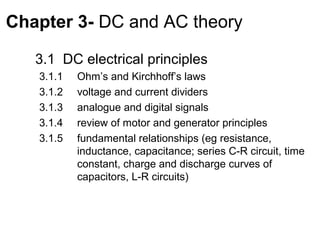
- 1. Chapter 3- DC and AC theory 3.1 DC electrical principles 3.1.1 Ohm’s and Kirchhoff’s laws 3.1.2 voltage and current dividers 3.1.3 analogue and digital signals 3.1.4 review of motor and generator principles 3.1.5 fundamental relationships (eg resistance, inductance, capacitance; series C-R circuit, time constant, charge and discharge curves of capacitors, L-R circuits)
- 2. Electrical current Electrical current is the rate of flow of electrical charge through a conductor or circuit element. The units are amperes (A), which are equivalent to coulombs per second (C/s).
- 3. Mathematical relationship dq (t ) i (t ) = dt t q (t ) = ∫ i (t )dt + q (t0 ) t0
- 4. Direction of current The current direction in the circuit elements (a) Indicating current i1 flows from a to b (b) Indicating current i2 flows from b to a
- 5. Voltage The voltage associated with a circuit element is the energy transferred per unit of charge that flows through the element. The units of voltage are Volts (V), which are equivalent to joules per coulomb (J/C). Note: Relationship between voltage and current is given by ohms law
- 6. Direction of voltage drop The voltage vab has a reference polarity that is positive at point a and negative at point b The positive reference for v is at the head of the arrow.
- 7. Resistor • A resistor is a circuit element that dissipates electrical energy (usually as heat) • Eg: incandescent light bulbs, heating elements (stoves, heaters, etc.), long wires • It may be lumped (eg: bulbs) or continuous type (distribution lines) • Resistance is measured in Ohms (Ω) • Demonstration of colour code calculator
- 8. Resistance Related to Physical Parameters ρL R= A ρ is the resistivity of the material used to construct the resistor (Unit is Ohm-meter)
- 12. Resistor construction Old style carbon resistor: Ceramic cylinder with thin film layer that is made converted into a special carbon wire by cutting groves in the cylinder New style carbon resistor: Ceramic plate with carbon film layer that is converted into long zig-zag wire with groves
- 13. Questions to think • Why carbon is used for resistors • Why did they change in shape • Why use resistors • How the power rating of the resistor get changes • What is the standard symbol of a resistor • What is a conductor
- 14. Ohms law • Ohms law: Current through a resistor is proportional to the voltage applied across it at a given temperature • Ohms law establishes a relationship between voltage and current. It can be mathematically expressed as I ∝V 1 V- Voltage I = V R I – Current V = IR R - Resistance
- 15. Resistors and Ohm’s Law a v = iR vab = iab R b
- 16. Power and energy p(t ) = v (t )i (t ) P - Power (J/s or W) t2 w = ∫ p(t )dt W - energy (J) t1 p(t) = v(t)i(t) From ohms law v(t) = i(t)R or i(t) = v(t)/R p(t) = i2(t) R = v2(t)/R
- 17. Example: a 25W Bulb • If the voltage across a 25W bulb is 120V, what is its resistance? R = V2/P = (120V)2/25W = 576 Ω • What is the current flowing through the 25W bulb? I = V/R = 120V/576 Ω = 0.208 A
- 18. Thought Question • When measured the resistance of a 25W bulb, the value got was about 40Ω. What’s wrong here? • Answer: The resistance of a wire increases as the temperature increases. For tungsten, the temperature coefficient of resistivity is 4.5x10⁻³/oK. A light bulb operates at about 5000oF.
- 19. Direct Current (DC) and Alternating Current (AC) When a current is constant with time, we say that we have direct current, abbreviated as dc. On the other hand, a current that varies with time, reversing direction periodically, is called alternating current, abbreviated as ac.
- 20. dc and ac current waveforms .
- 21. ac currents can have various waveforms
- 22. See the list of circuit elements
- 24. Kirchoff’s law • KIRCHHOFF’S CURRENT LAW (KCL) The net current entering a node is zero. Alternatively, the sum of the currents entering a node equals the sum of the currents leaving a node. • KIRCHHOFF’S VOLTAGE LAW (KVL) The algebraic sum of the voltages equals zero for any closed path (loop) in an electrical circuit
- 25. KCL (Kirchhoff’s Current Law) i1(t) i5(t) i2(t) i4(t) i3(t) The sum of currents entering the node is n zero: ∑ i (t ) = 0 j =1 j Analogy: mass flow at pipe junction
- 26. KVL (Kirchhoff’s Voltage Law) + – v2(t) + + v1(t) v3(t) – – • The sum of voltages around a loop is zero: n ∑ v j (t ) = 0 j =1 • Analogy: pressure drop thru pipe loop
- 27. KVL Polarity • A loop is any closed path through a circuit in which no node is encountered more than once • Voltage Polarity Convention – A voltage encountered + to - is positive – A voltage encountered - to + is negative
- 28. In applying KVL to a loop, voltages are added or subtracted depending on their reference polarities relative to the direction of travel around the loop
- 29. Consider the circuit shown below. Use Ohm’s law, KVL, and KCL to find Vx
- 30. Using KVL, KCL, and Ohm’s Law to Solve a Circuit
- 31. 15 V iy = =3A 5Ω ix + 0.5ix = i y ix = 2 A
- 32. v x = 10ix = 20 V Vs = v x + 15 Vs = 35 V
- 33. Voltage Dividers • Resistors in series provide a mechanism • The resistors determine the output Voltage • KCL says same current in R1 and R2 • Vout = Example: Light dimmer (has a potentiometer V1 * R2/(R1+R2) which is a variable resistance). You dim the light by the ratio of resistors dropping the voltage going to the light bulb
- 35. Voltage Division R1 v1 = R1i = v total R1 + R2 + R3 R2 v 2 = R2 i = v total R1 + R2 + R3 R3 v3 = R3i = vtotal R1 + R2 + R3
- 36. Current Dividers • Resistors in parallel provide a mechanism • The resistors determine the current in each path • I1 * R1 = I2 * R2, I2 = I1 * R1/R2 • I = I1 + I2 I1 = I * R2/(R1+R2) I1 R1 I I2 R2
- 38. Current Division v R2 i1 = = itotal R1 R1 + R2 v R1 i2 = = itotal R2 R1 + R2
- 39. Example Dividers • Given 10V, Need to provide 3V, how? • Resistors in Series • R2/(R1+R2) = 3/10, choose R2 = 300 KΩ • R1 = 700 KΩ • Why should R1, R2 be high? • What happens when we connect a resistor R3 across R2?
- 40. Example Dividers • Want to divide current into two paths, one with 30% --how? • Resistors in parallel • R2/(R1+R2) = 0.3, Choose R2 = 300 KΩ • R1 = 700 KΩ • Why should R1, R2 be high? • What happens when we connect a resistor R3 in series with R2?
- 41. • Although the following concepts are very important they are not sufficient to solve all circuits – series/parallel equivalents – current/voltage division principles
- 42. Signal and waveform • A signal is a physical quantity, or quality, which conveys information • The variation of the signal value as a function of the independent variable is called a waveform • The independent variable often represents time • We define a signal as a function of one independent variable that contains information about the behavior or nature of a phenomenon • We assume that the independent variable is time even in cases where the independent variable is a physical quantity other than time
- 43. Continuous or analog signals • Continuous signal is a signal that exists at every instant of time • In the jargon of the trade, a continuous signal is often referred to as continuous time or analog • The independent variable is a continuous variable • Continuous signal can assume any value over a continuous range of numbers
- 44. Discrete-time signals • A signal defined only for discrete values of time is called a discrete-time signal or simply a discrete signal • Discrete signal can be obtained by taking samples of an analog signal at discrete instants of time • Digital signal is a discrete-time signal whose values are represented by digits
- 45. What is sampling? • Sampling is capturing a signal at an instant in time • Sampling means taking amplitude values of the signal at certain time instances • Uniform sampling is sampling every T units of time xk = x(kT ) = x(t ) t =0,±T ,±2T ,±3T , Sampling frequency or 1 sampling rate F0 = time step or T sample interval
- 46. Sinusoidal signal x s (t ) = X s sin( 2πf s t + φ s ) Amplitude Phase in radian (rad) xx(t) ==X ssin(2 ππf f st t++φφ) ) s (t) X sin(2 s 2 s s s s 2 Time in seconds (s) 0 s xx 0 s Frequency in Hertz (Hz) -2 -2-0.1 0 0.1 0.2 -0.1 0 0.1 0.2 tt
- 47. Modern Capacitors Ceramic and Electrolyte Capacitors High Voltage Capacitor Banks
- 48. Capacitor • Capacitors consist of two conductors( insulated from each other) which carry equal and opposite charges +q and –q. • If the capacitor is charged then there is a potential difference V between the two conductors • The material between the plates is insulating. It has no free charge; charge does not pass through the insulator to move from one plate to another. • The charge q is proportional to the potential difference V • q =CV • The proportionality constant C is called the capacitance of the capacitor. Its value depends on the geometry of the plates and not the charge or potential difference. The unit of capacitance is FARAD
- 49. Factors Affecting Capacitance Area – directly proportional to plate area, ‘A’ Spacing – inversely proportional to plate spacing, ‘d’ Dielectric-dependent on the dielectric as A C = ε ( Farad ) d ε = permittivity of dielectric ( F / m )
- 50. Capacitors in Parallel But V1=V2=V Total charge ie. Q = Q1+Q2 = C1V+C2V = V(C1+C2) =VCeq Where Ceq=C1+C2
- 51. Capacitors in Series V1+V2=V, Q/C1+ Q/C2 =V Q(1/C1 + 1/C2) =V, i.e. 1/Ceq = 1/C1 +1/C2 Therefore Ceq = (C1C2)/ (C1+C2)
- 52. Voltage-Current Relationship q(t ) = CVc (t ) dq (t ) dVc (t ) ic (t ) = =C dt dt dVc (t ) ∴ ic (t ) = C dt t 1 Vc (t ) = ∫ ic (t )dt + Vc (t0 ) C t0
- 53. Energy Stored in a Capacitor t w(t ) = ∫ v(t )i (t ) dt to t dv = ∫ v C dt to dt cancelling differential time and changing the limits to the corresponding voltages, we have v(t ) 1 2 1 q 2 (t ) =∫ Cv dv = Cv (t ) = v(t )q (t ) = 0 2 2 2C
- 54. CAPACITORS – DC Stores charge: Q (Coulombs) I =∆Q/∆T Flow of charge is Current: I (Amperes) I dVC I =C dt 1 VC = ∫ idt C The capacitor charges linearly till the voltage across it reaches the applied voltage after which the driving force is lost and the capacitor ‘blocks’ DC. Example: Time delay circuit
- 55. RC CIRCUIT – DC VC (t ) = V (1 − e −t / RC ) - VC + - VR + This is similar but the capacitor charges non-linearly till the voltage across it reaches the applied voltage after which the driving force is lost. Time constant τ=RC is τ the time in which the capacitor is charged to 67%
- 56. RC CIRCUIT – DC Vo After a capacitor has charged to - VC(t) + I V0, it discharges if there is a resistance in the external circuit (otherwise it retains the charge : Vo use in DRAMs). The discharge is non-linear VC (t ) = V0 e − t / RC Time constant = RC Example: Discharge the defibrillator capacitor into the heart • We will return to Capacitors in the section ‘Impedance’ to consider their frequency response.
- 57. Modern Inductors
- 58. Relationship Between Electricity and Magnetism • Electricity and magnetism are different facets of electromagnetism – a moving electric charge produces magnetic fields – changing magnetic fields move electric charges • This connection first elucidated by Faraday, Maxwell
- 59. Magnetic Fields from Electricity A static distribution of charges produces an electric field Charges in motion (an electrical current) produce a magnetic field electric current is an example of charges (electrons) in motion
- 60. Faraday’s Law Faraday’s Law :A voltage is induced in a coil whenever its flux linkages are changing Induced EMF produced by a changing Magnetic Flux!
- 61. Self Inductance d λ di di e = v(t ) µ µ =L dt dt dt di ∴ v(t ) = L dt t 1 i ( t ) = ∫ v ( t ) dt + i ( t0 ) L t0
- 62. Inductances in Series v(t ) = v1 (t ) + v2 (t ) + v3 (t ) di (t ) di (t ) di (t ) v (t ) = L1 + L2 + L3 dt dt dt di (t ) v (t ) = Leq dt
- 63. Inductances in Parallel i (t ) = i1 (t ) + i2 (t ) + i3 (t ) di 1 1 1 = v(t ) + v(t ) + v(t ) dt L1 L2 L3 di (t ) v (t ) = Leq dt
- 64. Energy stored in an inductor To compute power, p(t) p(t ) = v(t )i (t ) di di = L i (t ) = Li dt dt To compute energy, w(t) t di w(t ) = ∫ p (t )dt = ∫ Li dt t0 dt i (t ) i (t ) i 2 1 2 = ∫ Lidi = L 2 0 w(t ) = Li (t ) 0 2
- 66. Transients • The time-varying currents and voltages resulting from the sudden application of sources, usually due to switching, are called transients. By writing circuit equations, we obtain integro-differential equations.
- 67. Mathematical Model - Discharging dvC ( t ) vC ( t ) C + =0 dt R vC ( t ) = Ke st dvC ( t ) RC + vC ( t ) = 0 dt RCKse + Ke = 0 st st vC ( t ) = Vi e −t RC
- 68. Mathematical Model - Charging dvC ( t ) vC ( t ) Vs C + = dt R R vC ( t ) = A + Ke st dvC ( t ) RC + vC ( t ) = Vs dt RCKse + A + Ke = Vs st st vC ( t ) = Vs − Vs e −t τ
- 69. Mathematical Model – RL Circuit R t=0 di L + R ⋅ i = Vs Vs i(t) L v(t) dt i( t ) = K1 + K 2 e st sLK 2 e st + RK 2 e st + RK1 = Vs i( t ) = Vs R ( 1 − e −t τ ) L τ= R
- 70. Step by step solution procedure • Circuits containing a resistance, a source, and an inductance (or a capacitance) 1. Write the circuit equation and reduce it to a first- order differential equation. 2. Find a particular solution. The details of this step depend on the form of the forcing function. 3. Obtain the complete solution by adding the particular solution to the complementary solution
- 71. Use of sinusoidal waveforms Sinusoidal waveforms are of special interest for a number of reasons: it is a natural form occurring in an oscillator circuit; also the form of voltage induced in a turn (coil) of wire rotated in a magnetic field, ie. a generator it is the form of voltage used for both distribution of electricity and for communications all periodic waveforms can be represented as a series of sine waves using fourier analysis.
- 72. Coil rotating in a magnetic field For uniformity, we express sinusoidal function using cosine function rather than the sine function. The functions are related by the identity π sin ( θ ) = cos θ − ÷ 2 π cos θ = sin(θ + ) 2 Induced voltage and resulting current in a coil rotating in a magnetic field is sinusoidal
- 73. Sinusoidal Waveform Vm cos ( ωt + θ ) Vm is the peak value ω is the angular frequency in radians per second θ is the phase angle T is the period 1 Frequency f = T 2π Angular frequency ω= T ω = 2πf
- 74. Root Mean Square Values T 2 1 v 2 ( t ) dt V Vrms = T ∫ Pavg = rms 0 R T 1 v 2 (t ) Pavg = ∫ dt T T0 R 1 Pavg = I 2 R I rms = ∫ i ( t ) dt 2 rms 1 T 2 T ∫ v (t )dt 2 0 RMS Value of a Sinusoid T 0 Pavg = Vm Im R Vrms = I rms = 2 2 The rms value for a sinusoid is the peak value divided by the square root of two. This is not true for other periodic waveforms such as square waves or triangular waves!
- 75. Power in AC Circuits • Instantaneous power v ( t ) = Vm cos ( ωt + θ v ) i ( t ) = I m cos ( ωt + θi ) p ( t ) = v ( t ) × i ( t ) = Vm I m cos ( ωt + θ v ) cos ( ωt + θi ) 1 1 = Vm I m cos ( θv − θi ) + Vm I m cos ( 2ωt + θ v + θi ) 2 2 V I • Average power P = p ( t ) = m ÷ m ÷cos ( θ v − θ i ) 2 2 • Power Factor PF = cos ( θ v − θ i ) V I • Reactive Power Q = m ÷ m ÷sin ( θ v − θi ) 2 2 V I • Apparent Power = m ÷ m ÷ 2 2