12. 1-2 WS2000 Wireless Switch System Reference Guide
1.1 WS2000 Wireless Switch System Reference Guide
This guide is intended to support administrators responsible for understanding, configuring and maintaining
the Wireless Switch. This document provides information for the system administrator to use during the
initial setup and configuration of the system. It also serves as a reference guide for the administrator to use
while updating or maintaining the system.
1.1.1 About this Document
We recommend viewing this online system reference guide with Internet Explorer 5.0 and higher or Netscape
Navigator 4.7 or higher on a Microsoft Windows based PC. Viewing this document under other
configurations may produce undesirable results.
1.1.2 Document Conventions
NOTE: Indicates special tips or requirements
CAUTION: Indicates a condition that can cause equipment damage or data loss
WARNING! Indicates a condition or procedure that could result in personal injury or equipment
damage
GUI Screen Text Indicates monitor screen dialog/output from the graphical user interface accessed from
any web browser on the network.
13. Product Overview 1-3
1.2 System Overview
The WS2000 Wireless Switch provides a low-cost, feature-rich option for sites with one to six Access Ports.
The WS2000 Wireless Switch works at the center of a network’s infrastructure to seamlessly and securely
combine wireless LANs (WLANs) and wired networks. The switch sits on the network. Wireless Access Ports
connect to one of the six available ports on the switch and the external wired network (WAN) connects to a
single 10/100 Mbit/sec. WAN port.
Mobile units (MUs) associate with the switch via an Access Port. When an MU contacts the switch, the
switch cell controller services attempt to authenticate the device for access to the network.
The WS2000 Wireless Switch acts as a WAN/LAN gateway and a wired/wireless switch.
1.2.1 Management of Access Ports
This wireless switch provides six 10/100 Mbit/sec. LAN ports for internal wired or wireless traffic. Four of
these ports provide IEEE 802.3af-compliant Power over Ethernet (PoE) support for devices that require power
from the Ethernet connection (such as Access Ports). Administrators can configure the six ports to
communicate with a private LAN or with an Access Port for a wireless LAN (WLAN). The switch provides up
to four extended service set identifiers (ESSIDs) for each Access Port connected to the switch.
1.2.1.1 Firewall Security
The LAN and Access Ports are placed behind a user-configurable firewall that provides stateful packet
inspection. The wireless switch performs network address translation (NAT) on packets passing to and from
the WAN port. This combination provides enhanced security by monitoring communication with the wired
network.
1.2.1.2 Wireless LAN (WLAN) Security
Administrators can configure security settings independently for each ESSID. Security settings and protocols
available with this switch include:
• Kerberos
• WEP-64
• WEP-128
• 802.1x with RADIUS
• 802.1x with Shared Key
• KeyGuard
• WPA/WPA2-TKIP
• WPA2/CCMP (802.11i)
1.2.1.3 VPN Security
Virtual Private Networks (VPNs) are IP-based networks that use encryption and tunneling to give users
remote access to a secure LAN. In essence, the trust relationship is extended from one LAN across the public
network to another LAN, without sacrificing security. A VPN behaves similarly to a private network; however,
because the data travels through the public network, it needs several layers of security. The WS2000
Wireless Switch acts as a robust VPN gateway.
14. 1-4 WS2000 Wireless Switch System Reference Guide
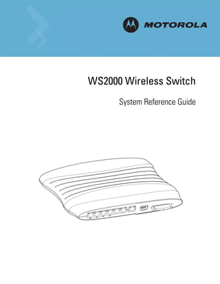
1.3 Hardware Overview
The WS2000 Wireless Switch provides a fully integrated solution for managing every aspect of connecting
wireless LANs (WLANs) to a wired network. This wireless switch can connect directly to a cable or DSL
modem, and can also connect to other wide area networks through a Layer 2/3 device (such as a switch or
router). The switch includes the following features:
• One WAN (RJ-45) port for connection to a DSL modem, cable modem, or any other Layer 2/3 network
device.
• Six 10/100 Mbit/sec. LAN (RJ-45) ports: four ports provide 802.3af “Power over Ethernet” (PoE) support;
the other two do not provide power.
• Each port has two LEDs, one indicating the speed of the transmission (10 or 100 Mbit/sec.), the other
indicating whether there is activity on the port. The four LAN ports with PoE have a third LED that
indicates whether power is being delivered over the line to a power device (such as an Access Port). (See
the WS2000 Wireless Switch LED explanation for more information on the meaning of the different state
of the LEDs.)
• A DB-9 serial port for direct access to the command-line interface from a PC. Use Symbol’s Null-Modem
cable (Part No. 25-632878-0) for the best fitting connection.
• A CompactFlash slot that provides AirBEAM® support.
1.3.1 Technical Specifications
1.3.1.1 Physical Specifications
• Width: 203 mm
• Height: 38 mm
• Depth: 286 mm
• Weight: 0.64 kg
1.3.1.2 Power Specifications
• Maximum Power Consumption: 90-256 VAC, 47-63 Hz, 3A
• Operating Voltage: 48 VDC
• Operating Current: 1A
• Peak Current: 1.6A
1.3.1.3 Environmental Specifications
• Operating Temperature: 0ºC to 40ºC
• Storage Temperature: -40ºC to 70ºC
• Operating Humidity: 10% to 85% Non-condensing
• Storage Humidity: 10% to 85% Non-condensing
• Operating Altitude: 2.4 Km
• Storage Altitude: 4.6 km
15. Product Overview 1-5
1.3.2 WS2000 Wireless Switch LED Functions
The switch has a large blue LED on the right front that indicates that the switch is powered on.
Each port on the WS2000 Wireless Switch has either two or three LEDs that indicate the status of the port.
Ports 1-4, which supply 802.3af Power over Ethernet (PoE), have three LEDs. The remaining two non-powered
LAN ports and the WAN port have two LEDs.
Location Function
Upper left LED This LED is present on all ports and indicates the speed of the transmissions through
the port. The LED is on when the transmission rate is 100 Mbit per second (100BaseT).
The light is off when the transmission rate is 10 Mbit per second.
Upper right LED This LED indicates activity on the port. This light is solid yellow when a link to a device
is made. The light flashes when traffic is being transferred over the line.
Lower LED This LED is only present on Ports 1-4. These ports provide 802.3af Power over Ethernet
(PoE) support to devices (such as Access Ports). The LED has several states:
OFF—A non-power device (or no device) is connected; no power is being delivered.
GREEN—The switch is delivering 48 volts to the power device connected to that port.
RED—There was a valid PoE connection; however, the switch has detected that the
power device is faulty. The red light will remain until a non-faulty connection is made
to the port.
16. 1-6 WS2000 Wireless Switch System Reference Guide
1.4 Software Overview
The WS2000 Wireless Switch software provides a fully integrated solution for managing every aspect of
connecting Wireless LANs (WLANs) to a wired network, and includes the following components:
1.4.1 Operating System (OS) Services
Operating System (OS) Services determine how the WS2000 Wireless Switch communicates with existing
network and operating system-centric software services, including:
• Dynamic Host Configuration Protocol (DHCP)
• Telnet and File Transfer Protocol (FTP/TFTP) servers
• The Simple Network Time Protocol (SNTP) client, used to keep switch time synchronized for Kerberos
authentication
• A mechanism for setting up a redundant (secondary) switch that takes over if the primary switch fails
1.4.2 Cell Controller Services
The Cell Controller provides the ongoing communication between mobile units (MUs) on the Wireless LAN
(WLAN) and the wired network. Cell Controller services perform the following:
• Initialize the Access Ports
• Maintain contact with Access Ports by sending a synchronized electronic “heartbeat” at regular intervals
• Track MUs when they roam from one location to another
• Manage security schemes based on system configuration
• Maintain system statistics
• Store policies and Access Port information
• Detect and manage rogue Access Ports
• Management of communications QoS
1.4.3 Gateway Services
Gateway services provide interconnectivity between the Cell Controller and the wired network, and include
the following:
• System management through a Web-based Graphical User Interface (GUI) and SNMP
• 802.1x RADIUS client
• Security, including Secure Sockets Layer (SSL) and Firewall
• Network Address Translation (NAT), DHCP services, and Layer 3 Routing
• Virtual Private Network (VPN)
18. 2-2 WS2000 Wireless Switch System Reference Guide
2.1 Getting Started with the WS2000 Wireless Switch
This section provides just enough instruction to set up the WS2000 Wireless Switch, connect an Access Port,
and test communications with a single mobile unit (MU) and the wide area network (WAN). The configuration
suggestions made here are just the minimum needed to test the hardware. Once finished with this section,
additional configuration settings are required. This section covers the following topics:
• Step 1: Install the switch and connect it to the • Step 5: Configure Subnet1
WAN, a stand alone computer, and an Access • Step 6: Configure the WAN Interface
Port
• Step 7: Enable Wireless LANs (WLANs)
• Step 2: Set up administrative communication
to the switch • Step 8: Configure WLAN Security
• Step 3: Set the basic switch settings • Step 9: Test Connectivity
• Step 4: Configure the LAN interface
Step 1: Install the Switch
To install the WS2000 Wireless Switch hardware, follow the directions in the WS2000 Wireless Switch
Quick Installation Guide found in the box with the switch and on the CD-ROM that is distributed with the
switch. These instructions describe how to:
• Select a site (desk, wall, or rack) for the switch
• Install the switch using the appropriate accessories for the selected location
• Connect devices to WAN and LAN ports (using standard CAT-5 cables)
• Interpret the port LEDs on the front of the switch
After the switch is mounted and powered up, connect the following items to the switch:
1. Connect the WAN to the switch (using the WAN port) with a CAT-5 Ethernet cable. The LEDs for that port
should start to flash.
2. Connect an Access Port to the switch using a CAT-5 Ethernet cable using one of the six LAN ports. If the
Access Port requires PPPoE, connect the Access Port in ports 1, 2, 3, or 4. Ports 5 and 6 do not provide
power.
3. Have a mobile “wireless” device available to test communication with the Access Port.
NOTE: Access Ports must be connected to the LAN ports of the wireless switch to enable configuration of
the Access Port related settings.
Step 2: Set Up Administrative Communication to the Switch
Before the configuration process can begin, establish a link with the wireless switch.
1. Connect a “wired” computer to the switch (in any one of the available LAN ports) using a standard
CAT-5 cable.
2. Set up the computer for TCP/IP DHCP network addressing and make sure that the DNS settings are not
hard coded.
3. Start up Internet Explorer (with Sun Microsystems’ Java Runtime Environment (JRE) 1.4 or higher
installed) and type the following IP address in the address field: 192.168.0.1
19. Getting Started 2-3
NOTE: For optimum compatibility use Sun Microsystems’ JRE 1.4 or higher (available from Sun’s website),
and be sure to disable Microsoft’s Java Virtual Machine if it is installed.
The following screen displays.
4. Log in using admin as the User ID and symbol as the Password.
5. If the login is successful, the following dialog window displays.
Enter a new admin password in both fields, and click the Update Password Now button. When the
admin password has been updated, the following message displays, and you are prompted to change the
country of operation for the switch.
6. Select and change the country from the Country drop-down list of the System Settings screen.
7. Click the Apply button to save the changes.
The System Setting screen is displayed.
20. 2-4 WS2000 Wireless Switch System Reference Guide
Step 3: Set the Basic Switch Setting
1. Enter a System Name for the wireless switch. The specified name appears in the lower-left corner of
the configuration screens, beneath the navigation tree. This name can be a useful reminder if multiple
Motorola wireless switches are being administered.
2. Enter a text description of the location of the switch in the System Location field. This text is used as
a reminder to the network administrator and is also used to set the location variable if the switch is
administered using SNMP.
3. In the Domain Name field, enter the name of the domain this switch is a member of. This value is
returned along with the system name for a Reverse DNS Query on the switch.
4. Enter an email address for the administrator in the Admin Email Address field. The switch uses this
address for sending SNMP-related and other administration-related messages to the administrator.
5. Enter the IP address of the DNS Name Server in the DNS Server IP Address field. The switch uses this
field to resolve FQDN information provided in the NTP configuration page. See Specifying a Network
Time Protocol (NTP) Server for more information.
6. Select the Country for the switch from the drop-down menu. Selecting the correct country is extremely
important. Each country has its own regulatory restrictions concerning electromagnetic emissions and
the maximum RF signal strength that can be transmitted by Access Ports. To ensure compliance with
national and local laws, be sure to set this field accurately.
7. Keep the Enable DNS Relay option checked. If not checked, clients on the LAN side of the WS2000 will
not be able to use a DNS server to resolve URLs.
8. Click Apply to save changes. Unapplied changes are lost if the administrator navigates to a different
screen.
21. Getting Started 2-5
NOTE: The WS2000 switch is shipped with an open default SNMP configuration:
Community: public, OID: 1.3.6.1, Access: Read-only
Community: private, OID: 1.3.6.1, Access: Read-write
If your switch has these settings, it is important to change them immediately; otherwise, users on the
same network will have read-write access to the switch through the SNMP interface. Select [System
Configuration] --> SNMP Access from the left menu to examine the settings and change them, if
necessary.
Step 4: Configure the LAN Interface
The first step of network configuration process is to figure out the topology of the LAN. The WS2000
Wireless Switch allows the administrator to enable and configure six different subnets. The administrator
can assign an IP address, port associations, and DHCP settings for each subnet.
Enable Subnet1
Select LAN under the Network Configuration group from the left menu. Use the LAN configuration screen to
view a summary of physical-port addresses and wireless LANs (WLANs) associated with the six supported
subnets, and to enable or disable each configured subnet.
1. In the LAN screen, the administrator can enable up to six subnets. Make sure that the check box to the
left of Subnet1 line is enabled.
Each enabled subnet shows up in the directory tree in the left column of the configuration screens.
Consider disabling a previously configured subnet if its assigned ports are no longer in use, or to
consolidate the LAN’s communications on fewer subnets.
The rest of the information on this screen is summary information; it is collected from other screens (such as
the subnet configuration screens) where the administrator can set the data.
Network Network (subnet) name is a descriptive string that should describe the subnet’s function. The
WS2000 Network Management System uses subnet names throughout the configurations
screens.
22. 2-6 WS2000 Wireless Switch System Reference Guide
Address This IP address allows users from outside the subnet (whether from the WAN or from another
subnet from the same switch) to access the right subnet. An IP address uses a series of four
numbers that are expressed in dot notation, for example, 194.182.1.1.
Interfaces The Interfaces field displays which of the six physical LAN ports are associated with the
subnet. The possible ports are: P1 (port 1), P2, P3, P4, P5, and P6 (from left to right facing the
front of the switch). The administrator assigns a port to a subnet to enable access to the
device(s) connected to that port. The administrator can assign a port to only one subnet.
The Interfaces field also lists the WLANs that are associated with the subnet.
Step 5: Configure Subnet1
The WS2000 Network Management System allows the administrator to define and refine the configuration
of the enabled subnets. Each of six subnets (short for “subnetworks”) can be configured as an identifiably
separate part of the switch-managed local area network (LAN). Each subnet can include some combination
of assigned ports and associated wireless LANs (WLANs).
1. Select [Network Configuration] --> LAN --> Subnet1 from the list on the left. The following screen
appears for the selected subnet.
2. Check to make sure that all the ports and WLAN1 are selected for this subnet. WLAN1 should
automatically be included if the switch and the Access Port are communicating properly. If WLAN1 is not
present in the list, check the following:
• The power to the Access Port
• The connections between the switch and the Access Port
• The LEDs to make sure that lights are on and flashing
23. Getting Started 2-7
3. For this initial configuration, ensure that This interface is a DHCP Server is enabled. If so, the switch
sets the IP addresses automatically for the mobile devices. This value can be changed at any time in the
future. All other default settings are fine for the system test.
DHCP is a protocol that includes mechanisms for IP address allocation and delivery of host-specific
configuration parameters from a DHCP server to a host. Some of these parameters are IP address,
network mask, and gateway. The switch includes internal DHCP server and client features, and the
subnet’s interface can use either capability.
4. Click the Apply button to save changes.
Step 6: Configure the WAN Interface
A wide area network (WAN) is a widely dispersed telecommunications network. In a corporate environment,
the WAN port might connect to a larger corporate network. For a small business, the WAN port might
connect to a DSL or a cable modem to access the Internet.
The WS2000 Wireless Switch includes one WAN port. In order to set up communications with the outside
world, select [Network Configuration] --> WAN from the left menu. The following WAN configuration
page appears.
Communicating with the Outside World
1. Click the Enable WAN Interface check box to enable a connection between the switch and a larger
network or the outside world through the WAN port.
2. If this switch should be a DHCP client (A DHCP client get it’s IP address automatically from a DHCP server
or a switch), check the This interface is a DHCP Client check box to enable it. If This interface is
DHCP Client is checked, the switch is limited to one WAN IP address. This choice is required when:
• The host router or switch on the WAN communicates with the WS2000 Wireless Switch using DHCP.
• The switch interfaces with an Internet Service Provider (ISP) that uses DHCP addressing.
24. 2-8 WS2000 Wireless Switch System Reference Guide
NOTE: This setting is independent from the DHCP settings for the switch’s internal subnets.
3. If This interface is DHCP Client is not checked, other fields in the screen are enabled. To find out the
information to enter into these fields, contact your network administrator or the ISP that provided the
cable modem or DSL router. All fields take standard IP addresses in the form xxx.xxx.xxx.xxx.
• IP Address refers to the IP address that the outside world uses to address this WS2000 Wireless
Switch.
• Click the More IP Addresses button to specify additional static IP addresses for the switch.
Additional IP addresses are required when users within the LAN need dedicated IP addresses, or
when servers in the LAN need to be accessed (addressed) by the outside world. The pop-up window
allows the administrator to enter up to eight WAN IP addresses for the switch.
• The Subnet Mask is the mask used for the WAN.
• The Default Gateway is the address of the device that provides the connection to the WAN (often
a cable modem or DSL router).
• The two DNS Server fields specify DNS addresses of servers that can translate domain names, such
as www.motorola.com, into IP addresses that the network uses when passing information. The
Secondary DNS Server acts as a backup to the Primary DNS Server when the primary server is
not available.
Setting Up Point-to-Point over Ethernet (PPPoE) Communication
Point-to-Point over Ethernet (PPPoE) provides the ability to connect a network of hosts through a simple
device to a remote access concentrator. Many DSL providers require that their clients communicate using
this protocol. The facility allows the ISP to control access, billing, and type of service provided to clients on
a per-user or per-site basis. Check with the network administrator or ISP to determine whether to enable this
feature, and, if so, find out the username and password required for authentication.
To set up PPPoE, click on the PPPoE tab under the WAN screen.
1. Check Enable in the PPP over Ethernet area to enable the PPPoE protocol for high-speed connections.
2. Enter the Username and Password required for authentication. The username and password are for
the switch’s router to use when connecting to the ISP. When the Internet session starts, the ISP
authenticates the username.
3. Set the Idle Time in seconds to an appropriate number. This number is the amount of time the PPPoE
connection will remain idle before it disconnects. 10000 seconds default idle time is appropriate for most
situations.
4. Check Keep Alive to instruct the switch to continue occasional communications over the WAN even
when client communications to the WAN are idle. Some ISPs terminate inactive connections, while
others do not. In either case, enabling Keep-Alive mode keeps the switch’s WAN connection alive, even
when there is no traffic. If the ISP drops the connection after reaching the maximum idle time, the switch
automatically reestablishes the connection to the ISP.
5. Select the appropriate WAN authentication method from the drop-down menu. Collect this information
from the network administrator. Select between None, PAP, CHAP, or PAP or CHAP.
25. Getting Started 2-9
CHAP A type of authentication in which the user logging in uses a secret information and some
special mathematical operations to calculate a numerical value. The server, the user is
logging into, knows the same secret value and performs the same mathematical operations
to arrive at a value. If the values match, the user is authorized to access the server. One of
the numbers used in the mathematical operation is changed after every log-in. This is to
protect the server against an intruder secretly copying a valid authentication session and
replaying it later to log in.
PAP An identity verification method used to send a username and password over a network to a
computer that compares the username and password to a table listing authorized users. This
method of authentication is less secure, because the username and password travel as clear
text that a hacker could read and use to launch an attack.
6. Click the Apply button to save changes.
Step 7: Enable Wireless LANs (WLANs)
The WS2000 Wireless Switch works either in a wired or wireless environment; however, the power of the
switch is associated with its support of wireless networks. In order to use the wireless features of the
switch, the administrator needs to enable up to four wireless LANs (WLANs).
To start the WLAN configuration process, select the [Network Configuration] --> Wireless item from the
left menu. The following Wireless screen appears.
Wireless Summary Area
The top portion of the window displays a summary of the WLANs that are currently defined. This is the
screen in which the administrator can enable or disable a WLAN. At first, eight WLANs are listed WLAN1,
WLAN2, WLAN3, WLAN4, WLAN5, WLAN6, WLAN7 and WLAN8; however, only WLAN1 is enabled.
1. Verify that WLAN1 is enabled (checked) and associated with Subnet1.
26. 2-10 WS2000 Wireless Switch System Reference Guide
2. Verify that Access Port 1 is shown in the Access Ports Adopted field to the right. If it is not, verify the
connection between the switch and the Access Port.
The current settings for the associated Subnet and adopted Access Ports are displayed on this screen;
however, the screen associated with each WLAN (under [Network Configuration] --> Wireless) is where
the settings and rules for adopting Access Ports can be modified.
Use the AP Adoption Configuration tab to assign Access Ports to a particular WLAN. The switch can adopt
up to six Access Ports at a time, but the list of allowed Access Port addresses (displayed in this area) can
exceed six in number. A dual-radio 802.11a/b Access Port counts as one Access Port with respect to the
maximum allowed; however, each radio is listed as a separate Access Port.
This adoption list identifies each Access Port by its Media Access Control (MAC) address. This address is the
Access Port’s hard-coded hardware number that is printed on the bottom of the device. An example of a MAC
address is 00:09:5B:45:9B:07.
The default setting associates all adopted Access Ports with WLAN1.
Step 8: Configure WLAN Security
In the previous step, the administrator set parameters for each WLAN that fine tune the performance of the
WLAN. In addition, the administrator can set the type and level of security for each WLAN. These security
measures do not control communications from the WAN; instead, they control communication from the
clients within the WLAN.
In the [Network Configuration] --> Wireless --> <WLAN name> --> <WLAN Name> Security screen, the
administrator can set the user authentication method and the encryption method, as well as define a set of
rules that control which MUs can communicate through the WLAN.
27. Getting Started 2-11
Setting the Authentication Method
The authentication method sets a challenge-response procedure for validating user credentials such as
username, password, and sometimes secret-key information. The WS2000 Wireless Switch provides two
methods for authenticating users: 802.1x EAP and Kerberos. The administrator can select between these two
methods. For testing connectivity, WLAN security is not an issue, so there is not reason to enable
authentication—the default setting (No Authentication) is sufficient.
Setting the Encryption Method
Encryption applies a specific algorithm to data to alter its appearance and prevent unauthorized reading.
Decryption applies the algorithm in reverse to restore the data to its original form. Sender and receiver
employ the same encryption/decryption method.
Wired Equivalent Privacy (WEP) is a security protocol specified in the IEEE Wireless Fidelity (Wi-Fi) standard,
802.11b. WEP is designed to provide a WLAN with a level of security and privacy comparable to that of a
wired LAN. WEP might be all that a small-business user needs for the simple encryption of wireless data.
However, networks that require more security are at risk from a WEP flaw. An unauthorized person with a
sniffing tool can monitor a network for less than a day and decode its encrypted messages.
For the connectivity test, set WEP 128 encryption. This ensures that communications with the switch are
secure enough for this stage. Later on, increasing the security level might be necessary.
1. Select the WEP 128 (104-bit key) option.
2. To use WEP encryption with the No Authentication selection, click the WEP Key Settings button to
display a sub-screen for entering keys.
3. Add a key to Key #1, and use that key with the mobile unit. The keys consist of 26 hexadecimal
(0-9, A-E) characters. When finished, click the Ok button to close this screen an return to the WLAN
Security screen.
4. Click the Apply button in the WLAN Security screen to save changes.
Mobile Unit Access Control List (ACL)
This list is used to specify which mobile units can or cannot gain access to the WLAN. The list employs an
adoption rule for allowing or denying specific mobile units by way of exception. By default, all mobile units
can gain access.
28. 2-12 WS2000 Wireless Switch System Reference Guide
Step 9: Test Connectivity
At this point, the switch is set up to allow mobile units to access the LAN.
1. Check and ensure that the MU is setup as a DHCP client.
2. Set the MU to use WEP 128 bit encryption. Use the same key as was entered in the WEP Key Setting
dialog. You might need to restart the MU after changing the settings.
3. Open a Web browser and type the IP address: 192.168.0.1.
The WS2000 Switch Management screen should appear. If it does not, go back to the wired system used
to configure the switch and see if the mobile device appears in the MU Stats screen ([Status &
Statistics] --> MU Stats). If it does not appear on the MU Stats screen, recheck the network and WEP
settings on the mobile device.
4. In the Web browser, enter a URL for a site (such as www.motorola.com) on the WAN. If the site does not
appear, go to the WAN Stats screen ([Status & Statistics] --> WAN Stats) to review the status of the
WAN connection.
2.2 Where to Go from Here?
When full connectivity has been verified, the switch can be configured further to meet the needs of the
organization. Refer to the two case studies provided with this reference for specific installation examples.
These case studies describe the environment, the desired features, and the configuration selections that
were made in two different usage scenarios.
• Case 1: Retail Use Case
(with handheld terminals, wireless printers, wired POS, secured access to in-store server, and public
access to WAN)
• Case 2: Field Office Use Case
(with 3 WAN IP addresses, VPN passthrough, RADIUS server, and full-access between subnets)
30. 3-2 WS2000 Wireless Switch System Reference Guide
3.1 Enabling Subnets for the LAN Interface
Subnets are used to maximize the available network addresses and to logically separate the existing
organizational network into smaller related networks.
The WS 2000 Wireless Switch allows administrators to enable and configure six different subnets for each
switch. Administrators can assign IP addresses, port associations, DHCP settings, and security settings for
each subnet. This System Reference Guide provides two case studies that demonstrate how requirements
for network access and capabilities drive the decisions of how to configure the subnets.
3.1.1 Defining Subnets
Select LAN under the [Network Configuration] group from the left menu. Use the LAN configuration
screen to view a summary of physical-port addresses and Wireless LANs (WLANs) associated with the six
supported subnets, and to enable or disable each configured subnet.
1. Check the box to the left of a subnet to enable it. Up to six subnets can be enabled to use the wired and/
or wireless connections of the switch-managed LAN. Enable multiple subnets to divide the
communications of different business areas or operations. Each enabled subnet shows up in the directory
tree in the left column of the configuration screens. Consider disabling a previously configured subnet if
its assigned ports are no longer in use, or to consolidate the LAN’s communications on fewer subnets.
2. Click Update DNS for all Subnets to asynchronously invoke the Dynamic DNS update module. This
module checks the expired and valid DHCP leases for each of the subnets and adds or deletes entries to
the Dynamic DNS table accordingly.
3. Click Enable STP to enable STP. Spanning Tree Protocol (STP) is a protocol that ensures loop-free
topology for any bridged LAN. This feature is not enabled by default.
NOTE: STP is applied for mesh networks even if it is not enabled through the LAN screen.
31. LAN/Subnet Configuration 3-3
4. Click Apply to save changes. All “unapplied” changes are lost when the administrator moves to a new
screen.
The rest of the information on this screen is summary information. It is collected from other screens (such as
the subnet configuration screens) where the administrator can set the data.
Network Network (subnet) name is a descriptive string that should describe the subnet’s function. The
WS2000 Network Management System uses subnet names throughout the configurations screens.
Address This IP address allows users from outside the subnet (whether from the WAN or from another
subnet from the same switch) to access the right subnet. An IP address uses a series of four
numbers that are expressed in dot notation, for example, 194.182.1.1.
Interfaces The Interfaces field displays which of the six physical LAN ports are associated with the subnet.
The possible ports are: P1 (port 1), P2, P3, P4, P5, and P6 (from left to right facing the front of the
switch). The administrator assigns a port to a subnet to enable access to the device(s) connected
to that port. The administrator can assign a port to only one subnet.
The Interfaces field also lists the WLANs that are associated with the subnet.
To change features of a subnet, select [Network Configuration] --> LAN --> <subnet name> from the menu
on the left.
3.2 Configuring Subnets
The WS2000 Network Management System allows the administrator to define and refine the configuration
of the enabled subnets. Each of the six subnets (short for “subnetworks”) can be configured as an identifiably
separate part of the switch-managed Local Area Network (LAN). Each subnet can include some combination
of assigned ports and associated Wireless LANs (WLANs). To configure an enabled subnet, select the subnet
name from the [Network Configuration] --> LAN list in the left. The following screen appears for the
selected subnet.
32. 3-4 WS2000 Wireless Switch System Reference Guide
1. Change the Name of the subnet to use a descriptive name that indicates something about the subnet.
The name can contain seven characters, including spaces and numbers. It will appear in the left menu
under the LAN menu item.
2. Set an IP address to be used for the subnet.
The switch uses the IP address to refer to a particular subnet. This IP address could be a WAN address;
but is generally a non-routable address.
An IP address uses a series of four numbers that are expressed in dot notation, for example, 194.182.1.1.
3. Set the Network Mask for the IP address. A network mask uses a series of four numbers that are
expressed in dot notation, similar to an IP number. For example, 255.255.255.0 is a network mask.
4. Select a port or WLAN from the list of Interfaces to associate it with the subnet. Six LAN ports are
available on the switch. Assign from one to six ports to a subnet. Two subnets cannot use the same port.
However, multiple ports can be assigned to one subnet.
Eight WLANs are available. WLAN assignments are logical designations. Associate from zero to three
WLANs with a subnet. Two subnets cannot use the same WLAN. However, multiple WLANs can be
associated with one subnet. If two or three WLANs are associated with one subnet, each port dedicated
to that subnet can use any of the associated WLANs.
5. Click the Add button to add it to the Interfaces list.
To remove an interface, select that interface from the Assigned list and click the Delete button.
NOTE: Note that wireless devices cannot access the switch unless a WLAN is configured and associated
with a subnet. (This process is described in detail in Configuring Wireless LANs section of this document.)