Call Girls in Delhi, Escort Service Available 24x7 in Delhi 959961-/-3876
Honeywell 5883h-install-guide
1. ADEMCO 5883H
RF Transceiver
INSTALLATION AND SETUP GUIDE
INTRODUCTION MOUNT THE MODULE OR PC BOARD
The 5883H RF Transceiver Module: 5883H can be mounted remotely, or, with some controls, can be
! contains an RF receiver and a transmitter, mounted inside the control's cabinet. When mounting, make sure
! is intended for use with 5800 series RF transmitters, including bi- the antennas do not touch metal surfaces.
directional wireless units,
! receives alarm, status, and control messages from 5800 First, Check for RF Interference: Before mounting permanently,
transmitters, and passes these messages to the control panel via use the red RF Interference LED to check for strong local radio
wired connections, which then responds accordingly (arm/disarm frequency interference at the intended mounting location. If this
the system, initiate an alarm, etc.), LED is continuously lit, the 5883H module should be relocated.
! transmits system status and other conditions to bi-directional Removing the Cover
devices, Remove 5883H's cover by inserting a screwdriver blade in the slot at
! emulates the functions of a 5800TM module, the center of the cover's lower edge to release the locking tab.
! features a Spatial Diversity system that virtually eliminates the Replace the cover when installation is complete if unit is not
possibility of "Nulls" and "Dead Spots" within the coverage area, mounted within controls cabinet and secure with screw through
! incorporates new high-security encryption technology, and bottom locking tab.
! supports the number of zones shown in the chart at right.
Mounting inside the control's cabinet (refer to Fig. 2):
RF Zones Supported
1. Remove the 5883H’s circuit board from its base by bending back
5883H Depends on the control with which it is used. See
the two flexible plastic tabs that hold the board's lower edge.
the control panel’s instructions for specific details.
Discard the 5883H's unused plastic cover and base.
If "SET UP ERROR" (alpha keypads) or "E4 or “E8”" (fixed- 2. In the control's cabinet, unfasten and move the control circuit
word keypads) is displayed on the system's keypad, it indicates board downward (if already installed).
that more than the permitted number of wireless zones have 3. Hang two short (black) mounting clips (provided) on the raised
been programmed, and none of the zones will be protected. cabinet tabs in the cabinet, as shown in Detail B of Figure 2.
5800 SERIES 4. Insert the top of the 5883H’s board into the supporting slots at the
WIRELESS top of the cabinet (Detail A). Swing the bottom of the board into
TRANSMITTERS
CONTROL the two short (black) mounting clips installed in step 3, and
PANEL*
secure it to the cabinet with the accompanying screws.
KEYPAD 5. Insert the top of the control’s board into the slot in the black clips
TERMINALS 2-WAY holding the lower edge of the 5883H board (see Detail B); position
ON CONTROL 2-WAY
BOARD
TRANSMISSION two long (red) clips at the lower edge of the board (see Detail C).
WIRELESS
DATA OUT KEYPAD 6. Swing the lower edge of the control board into place, and secure
TO 5883
5883H with two additional screws.
TRANSCEIVER 7. Insert the grounding lugs (provided) through the top of the
DATA IN TO
CONTROL
cabinet and into the left-hand terminals of the antenna blocks (at
the upper edge of the 5883H's circuit board). Secure it to the
5883-003-V0
cabinet with the two screws provided, see Detail D.
*CONTROL MUST BE CAPABLE OF
SUPPORTING A 5800 RF SYSTEM
8. Insert the 5883H’s two antennas through the two openings in
the top of the cabinet, one into each block’s right-hand terminal,
and tighten the screws to secure them.
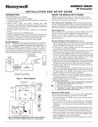
Figure 1. Block Diagram 9. Affix the 5883H's Summary of Connections label to the inside of
the control's cabinet door.
HOLES FOR ANTENNAS
AND GROUNDING LUGS CABINET ! All power-limited wiring must be separated from non-power
CIRCUIT BOARD
limited and high-voltage wiring by 1/4" (6.4 mm).
! All circuits are supervised.
UL ! Only one wire per terminal is permitted. If daisy-chained
BOARD
SUPPORTING RECEIVER CIRCUIT BOARD
(See Detail D) DETAIL A configuration is required, pig-tail wires together so that only a
SLOTS
+ +
SIDE VIEW
OF BOARD
single wire is terminated under the screw.
SUPPORTING SLOTS
MOUNTING
CLIP Mounting the 5883H remotely
CONTROL
CIRCUIT
NOTE: If mounting 5883H in its own enclosure, the supplied PCB
BOARD mounting clips, grounding lugs, and screws are not needed.
MOUNTING
CLIP 1. All wiring between the 5883H and the control panel must be
DETAIL B
located in a conduit.
SCREW
SIDE VIEW
OF MOUNTING
2. For concealed wiring, route wires through the rectangular
(2)
ANTENNA
(2)
CLIP
opening at the rear of the base before mounting. For surface
GROUNDING
LUG
(2)
wiring entry, a thin breakaway area is provided along the base's
CABINET
right edge.
3. Mount the module in the selected location. For greatest security,
RCVR BRD
DETAIL C use all four mounting holes (two key slot holes and two round
SIDE VIEW
+ + OF MOUNTING holes) in the plastic base. (Refer to Detail D in Figure 2 above.)
CLIP
ANTENNA 4. Install each antenna in the respective right-hand terminal of the
MOUNT
(2 PLACES) two terminal blocks at the upper edge of the 5883H’s circuit
DETAIL D
ANTENNA AND GROUNDING LUG INSTALLATION
pcb_RF_mount-V0
board, and tighten the screws to secure them.
Figure 2. Installing the 5883H Board in the Control’s Cabinet 5. Affix the 5883H's Summary of Connections label to the inside of
(Check the control’s Installation Instructions for applicability.) the housing cover
2. SET THE DIP SWITCHES NOTES:
Use the DIP switches to set the 5883H’s device address, to enable ! DIP switches 2–4 select both an RF receiver and an RF
the built-in transmitter, and to check or delete encrypted keys. transmitter device address.
! When used with 5800TM compatible (bi-directional) devices, the
Addresses: The 5883H Transceiver has two device addresses: one transmitter address must be enabled as a “keypad” in the control
for the receiver (addresses 1-7) and one for the transmitter and DIP switch 6 must be set to “ON.”
(addresses 27-30, similar to the 5800TM device addresses; see ! If 5883H is not being used with 5800TM compatible devices, the
notes 5 and 6 below). First, select a pair of addresses from the table RF transmitter address should be ignored and DIP switch 6
below, making sure that neither address is currently being used in should be set to OFF.
the alarm system, then use DIP switches 2-4 to set the address ! If programming the control to supervise 5883H, program only
pair. The addresses should then be programmed in the control. Do the receiver address for supervision. Do not program the
not program the transmitter’s address in the control if the 5883H transmitter address for supervision.
is not being used with 5800TM compatible devices. ! 5883H does not support the 5827BD Wireless Keypad.
DIP Switch Functions
Special Notes When Used With Certain Controls
Sw. Function
1 Check/deactivate high-security keys (see High-Security Keys paragraph)
Device Address Settings VISTA-40: When using bi-directional devices, use device address
Transmitter: Non- 28 29 30 27 28 29 30 setting 1/28 or 5/28 for devices used in partition 1; use device
Receiver: Addr.* 1 2 3 4 5 6 7 address setting 2/29 or 6/29 for devices used in partition 2 (this
2 OFF OFF OFF OFF ON ON ON ON is necessary because the VISTA-40 automatically assigns
3 OFF OFF ON ON OFF OFF ON ON
4 OFF ON OFF ON OFF ON OFF ON
address 28 or 29 depending on the programming in field 1*48,
5 Reserved - must be OFF wireless keypad partition assignment).
6 ON = enable transmitter (if using 5800TM compatible devices)
NOTE: If using more than one 5883H in a system, enable the VISTA 32FB, VISTA-50P and higher: When using bi-
transmitter in only one 5883H. directional devices, the Wireless Keypad Partition Assignment
OFF = disable transmitter
7 Not used; leave in OFF position field (typically 1*48) must be set to the partition in which the
8 Used when removing RF keypads (see Removing RF Keypads devices are used (cannot be used on Fire Partitions).
paragraph); otherwise leave OFF
! also address “0.” See VISTA-15P/20P note at right. VISTA-15P/20P Series, FA130C/FA148C/FA168CP Series:
Use device address setting of “non-addressable,” which is
address 0 (sets the receiver address; the transmitter address (for
bi-directional devices) is automatically set for 28).
CONNECT THE WIRING FROM THE CONTROL LED FUNCTIONS (refer to Figure 5)
1. Insert the wiring plug (with 5 flying leads) into the mating Red RF Interference LED: Lit Indicates local RF interference.
socket on the 5883H (see Figure 5 for socket location). Green LED: Flickering indicates reception of messages (decoded
2. Connect the 4 wires to the control's corresponding remote and/or non-decoded).
keypad connection points as follows: Yellow LED: Occasional blinks occur under normal operation.
RED 12VDC input (+) Aux Power Red LED: Blinks indicate available space for high security keys;
GREEN: Data to Control (control’s data IN) Steady ON indicates ready to deactivate high security keys or
YELLOW: Data from Control (control’s data OUT) remove wireless (RF) keypads. See High Security Keys and
BLACK: Ground (–) Wireless Keypads section.
IMPORTANT: Take precautions
ANTENNAS against static discharge when
(INSERT IN handling the 5883 PCB. A static
RIGHT-HAND discharge can damage the
TERMINALS) module’s EEPROM and/or cause
unpredictable changes in its
factory programming.
YELLOW TO
RED CONTROL'S
REMOTE
BLACK KEYPAD
5883 CIRCUIT BOARD GREEN CONNECTION
POINTS
RF INTERFERENCE
MOUNTING RED INDICATOR WIRING
HOLES OPENING
(4) GRN YEL RED
ON KNOCKOUT AREA
OFF 1 2 3 4 5 6 7 8 FOR SURFACE WIRING
DIP SWITCH
PLUG
TO RELEASE CIRCUIT BOARD, SOCKET
BEND BACK TABS
5883-002-V0
Figure 5. 5883H RF Transceiver
Page 2 of 4
3. PROGRAM CONTROL FOR RF OPERATION
Proceed with any control panel programming that may be
Deactivating High-Security keys
This procedure deactivates all enrolled high-security keys and is
necessary for RF operation and the instructions of the system's
required only if previously enrolled high-security keys are being
wireless transmitters, as described in the control's installation
replaced and there is not enough available space left for them in
instructions. In addition, note the following:
the receiver. Once this procedure is performed, all desired high-
! Enable the appropriate control data field for RF usage.
security keys must be re-enrolled to activate high-security
! Enroll the wireless keypad address(es), if used (see instructions operation.
provided with keypad). 1. Perform steps 1 and 2 in Checking Available Space procedure
! Wireless key buttons must first be enrolled in the control panel above.
via zone programming, and, where applicable, assigned to a 2. Wait until the RED LED lights steady ON then:
user number. Enroll each wireless key in 5883H by pressing the a. Record the positions of DIP switches 1 through 8.
appropriate buttons according to the instructions provided with b. Set DIP switches 1 through 8 to the opposite positions of
the key. their current settings and wait a few moments.
! Upon the successful enrollment of an encrypted key, the red c. Set DIP switches 1 through 8 back to their original positions
LED blinks the number of available spaces remaining for as recorded in step a. All enrolled high-security keys will be
additional encrypted key enrollment (see Checking Available deactivated.
Space For High Security Keys paragraph). 3. Set DIP switch 1 back to the OFF position to return to normal
! If more than one receiver is being used and you are using receiver operation (leave DIP 8 in OFF position).
encrypted wireless keys, we recommend that you:
a. Enter the GO/NO GO mode.
Removing All Wireless Keypads
b. Disconnect one receiver.
This procedure removes all wireless keypads from the transceiver.
c. Enroll all encrypted keys into the connected receiver.
1. Remove power from the transceiver and set DIP switches:
d. Reconnect the disconnected receiver.
DIP 1 = OFF
e. Exit the GO/NO GO mode.
DIP 8 = ON
f. Repeat steps a-e for the receiver that was disconnected.
2. Apply power and observe the RED LED lights steady ON, then:
a. Record the positions of DIP switches 1 through 8.
b. Set DIP switches 1 through 8 to the opposite positions of
their current settings and wait a few moments.
c. Set DIP switches 1 through 8 back to their original positions
as recorded in step a. All enrolled wireless keypads will be
HIGH SECURITY KEYS & WIRELESS KEYPADS removed from the transceiver.
Depending on the control panel used, the 5883H can support up 3. Set DIP switch 8 back to the OFF position to return to normal
to 16 high-security (encrypted) wireless keys and up to 16 receiver operation (leave DIP 1 in OFF position).
wireless keypads. The following paragraphs describe how to: NOTE: If unsure that correct RF keypad addresses are enabled in
! Check available space for high-security keys the receiver, you should perform the RF keypad delete
! How to deactivate all keys procedure, then enable RF keypad addresses as described in the
! How to remove all wireless keypads. instructions included with the RF keypad. Otherwise, erroneous
See the Control’s instructions and the appropriate device ECP device “check” messages may occur.
instructions for procedures on enrolling high security keys and
wireless keypads.
Checking Available Space for High Security Keys
The RED LED (above the DIP switch) shows (by blinking) how
many high-security keys may be enrolled into the transceiver.
1. Remove power from the transceiver and set DIP switches:
DIP 1 = ON
DIP 8 = OFF
2. Apply power and observe one of the following RED LED
indications:
a. Blinks, indicating the number of available spaces for
additional high-security key enrollment, and then lights
steady ON.
b. Immediate Steady ON (no blinks), indicating that high-
security key enrollment is full.
c. Off, indicating that no encrypted keys are enrolled.
3. Set DIP switch 1 back to the OFF position to return to normal
receiver operation (leave DIP 8 in OFF position).
Page 3 of 4