Marel Q1 2024 Investor Presentation from May 8, 2024
Dec1901a p002 009
1. Fuji Electric FA Components & Systems Co., Ltd./D & C Catalog
Information subject to change without notice01/2
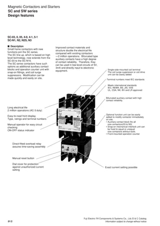
Magnetic Contactors and Starters
SC and SW series
Design features
SC-03, 0, 05, 4-0, 4-1, 5-1
SC-N1, N2, N2S, N3
I Description
Small frame contactors with new
functions join the SC series.
The SC line up, which is based on high
level technology, now extends from the
SC-03 to the SC-N16.
The SC series contactors have such
options as additional auxiliary contact
blocks and operation counter unit with
snap-on fittings, and coil surge
suppressors. Modification can be
made quickly and easily on site.
Improved contact materials and
structure double the electrical life
compared with existing contactors
—2 million operations. Bifurcated type
auxiliary contacts have a high degree
of contact reliability. Therefore, they
can be used in low-level circuits of 5V,
3mA and directly input to electronic
equipment.
Long electrical life
2 million operations (AC-3 duty)
Easy-to-read front display
Type, ratings and terminal numbers
Single-side-mounted coil terminal
The coil surge suppressor or coil drive
unit can be easily added
Terminal numbers meet IEC standards
Meets international standards
IEC, NEMA, BS, JIS, VDE
UL, CSA, NK, BV and LR approved
Bifurcated auxiliary contact with high
contact reliability
Optional function unit can be easily
added to modify contactor immediately
on site.
• Auxiliary contact block fits all
size contactors(03 to N3)
• Snap-on mechanical interlock unit can
be fixed to equal or unequal
size contactors without tools.
• Front-mounted operation counter
Manual operator for easy circuit
checking
ON-OFF status indicator
Direct-fitted overload relay
assures time-saving assembly
Manual reset button
Dial cover for protection
against unauthorized current
setting
Exact current setting possible
2. Fuji Electric FA Components & Systems Co., Ltd./D & C Catalog
Information subject to change without notice 01/3
01
Coil drive unit
Coil surge suppression unit
KKD06-021
Main circuit surge
suppression unit
KKD06-016
KKD06-024
Auxiliary contact
block
AF00-258
Mechanical interlock unit
KKD06-019
KKD06-013
Auxiliary
contact block KKD05-276
Operation counter
KKD06-017
Main circuit surge
suppression unit
AF89-1002
AF88-579
Terminal cover
KK04-086
AF00-258
Auxiliary contact block
Dial cover
Trip indicator
AF88-581
AF89-1003
Reset release button
KKD06-022
Magnetic Contactors and Starters
SC and SW series
Design features
I Easy modular system
G Side mounting
Auxiliary contact block
Single pole (1NO + 1NC)
Mechanical interlock unit
The mechanical interlock unit is used to
interlock two contactors for reversing.
One size fits all contactors.
Main circuit surge suppression unit
This unit prevents miss-operation of
electronic controllers due to motor surge
voltages.
G Top mounting
Coil drive unit
This unit controls ON-OFF operation for
magnetic contactors with output from
electronic equipment.
Coil surge suppression unit
This unit absorbs coil surge voltage due
to contactor ON-OFF operations.
G Front mounting
Auxiliary contact block
2-pole or 4-pole
Operation counter
This counter indicates the number of
contactor ON-OFF operations to ensure
easy maintenance and inspection.
Main circuit surge suppression unit
I Further information
See page 01/75
3. Fuji Electric FA Components & Systems Co., Ltd./D & C Catalog
Information subject to change without notice01/4
Specifications Contactors Starters(open)
Non-reversing reversing Non-reversing reversing
No.of thermal overload relay heater elements - - 3 3
Type SC-२ SC-२RM SW-२/3H SW-२RM/3H
Conformed New JIS Japan k k k k
IEC International k k k k
BS UK k k k k
EN Europe k k k k
Approved UL USA k k k k
CSA Canada k k k k
CCC China k * k * – –
EC Directives CE Marking Europe k k k k
Inspection Institute TÜV Germany k k k k
Magnetic Contactors and Starters
SC and SW series
Design features
SC-N1 to N16
I Description
FUJI SC series (SC-N5 to N16)
contactors have been developed and
manufactured using FUJI's most
advanced electronic technologies.
They employ an electronically-
controlled SUPER MAGNET which is
provided with a built-in IC, thus
enhancing their performance and
reliability. The SUPER MAGNET is
based on an “AC-input, DC-operated
concept“, thus allowing the coil to be
energized by both AC and DC input.
Moreover, once closed, sealed current
is controlled by switching circuit. This
permits a great reduction in power
consumption – a cost-effective feature.
The SC-N1 to SC-N4 are without
SUPER MAGNET. These contactors
feature compact size, arc extinguishing
mechanisms having a high breaking
efficiency, low power consumption,
operational ease and ratings up to 660
volts.
I Features of the SUPER MAGNET
• Operates on both AC and DC power
supply
• Has a wide operational voltage range
• No tendency to “chatter“
• Eliminates contact welding or coil
burning
• Reduces power consumption
In addition the FUJI SC-N series
contactors employ bifurcated auxiliary
contacts which improve contact
performance and permit them to be
used in conjunction with
programmable logic controllers.
FUJI SC-N series contactors are the
most suitable for new FA age
applications which require the most
advanced electronic technologies and
maximum dependability.
KK05-055
I The FUJI SC series conforms to and has been approved by various international
standards.
Notes k : Conforming to Standard
: A new certification mark that indicates compliance with both Canadian and U.S.requirements.
२ : Frame size N1 to N14 and N16(Contactor only)
* : When ordering the ccc standard type, add(ccc)suffix to the type number.
R
R
S
KK05-049KK04-087KK05-064
KK05-085
4. Fuji Electric FA Components & Systems Co., Ltd./D & C Catalog
Information subject to change without notice 01/5
01
I Advantages of SUPER MAGNET
G Positive pick-up and drop-out
The SUPER MAGNET operation is
electronically controlled. There is no
unstable zone as will be seen in the
diagram–an outstanding feature that
other contactors can not provide.
Chattering is a phenomenon which
occurs when the gravitational force of
the starter magnet decreases through
the line voltage drop at the time of
motor starting. This may cause
damage such as contact welding or coil
burning.
The SUPER MAGNET holds without
chattering even if the line voltage drops
to 65% of its rated value, so preventing
this type of trouble.
Motor starting Existing series SC-N series
Note: Unstable zone
In this zone contact welding and coil burning frequency occur due to voltage drop.
IC-controlled
SUPER MAGNET
G Operation on both AC and DC
inputs
The rated operational voltage range of
the SC-N series contactors has been
greatly expanded.
They operate on both AC (50/60Hz) and
DC inputs.
Rated Rated coil voltage, frequency
voltage
AC DC
24V 24–25V 50/60 Hz 24V
48V 48–50V 50/60 Hz 48V
100V 100–127V 50/60 Hz 100–120V *1
200V 200–250V 50/60 Hz 200–240V *2
300V 265–347V 50/60 Hz –
400V 380–450V 50/60 Hz –
500V 460–575V 50/60 Hz –
Notes: SC-N5 to N12: 24V–575V
SC-N14 to N16: 100V–575V
*1
: The coil voltage from a DC power supply with single
phase full-wave rectification will be 100 to 110 V.
*2
: The coil voltage from a DC power supply with single
phase full-wave rectification will be 200 to 220 V.
Coils (SC-N5 to SC-N16)
Pick-up
Voltage
Time
Coil operating signal
Coil current
Closing current
Sealed current
OFF
signal
Sealed
Drop-out
Sealed signal
ON
signal
Rated voltage
UNSTABLE
ZONE
Coil voltage
Gravitationalforce
Contacts
open
Unstable
zone
Contacts
closed
Ratedvoltage
Coil voltage
Gravitationalforce
Contacts
open
Contacts
closed
Ratedvoltage
Note: Since SC series contactors are electroni-
cally controlled there is no unstable zone.
Power
supply
AC or DC
Surge
suppression
circuit
Rectifier
circuit
IC-circuit
Voltage
detector
Closing
signal
circuit
Sealing
signal
circuit
Power
switching
circuit
COIL
Rated voltage
–15%
Pick-up
Operation
Allowable
operating
voltage
WIDE
RATINGS
Allowable
operating
voltage
+10%
Volts
200 250
Example: Coil voltage 200 volts use
with AC circuit 50 or 60Hz
INPUT
Magnetic Contactors and Starters
SC and SW series
Design features
Con-
tactor
ON
OFF
Motor inrush current
Line
voltage
NO CHATTERING
ZONE
65% of rated
voltage
Running current
Time
Motorcurrent
Instantaneous
voltage drops
Linevoltage(%)
Note: No chattering occurs even if instantaneous
voltage drops to 65% of rated voltage.
For further information, see page 01/30.
5. Fuji Electric FA Components & Systems Co., Ltd./D & C Catalog
Information subject to change without notice01/6
I Other advantages
G Terminal cover for finger protection
These optional terminal covers comply with VBG4 (German
Rules of Accident Prevention), IEC60529, DIN57106,
VDE0106 Teil100, which are recommendations for
preventing exposure to live parts.
The terminal cover satisfies the requirements of Machinery
Directive EN60204-1 “Direct Contact Prevention” concerning
mechanical safety.
G Insulation barrier
These optional insulation barriers prevent accidental short-
circuits caused by metallic objects falling onto the terminals.
G Live-section cover
An optional live-section cover that completely encloses the
front of a contactor or starter for increased worker safety
during maintenance and inspection.
G Insulation
Improved tracking resistance
Tracking resistance of the molded parts comprising of the
conductive block has been improved.
Comparative Tracking Index (CTI) : 175V or higher
Tracking : It means the route of the leak electric current caused on the
surface of the isolation body.
G Standard heat-proof material
The molded parts used are made of heat-proof materials
specified in UL94
(UL94 : STANDARD FOR SAFETY FOR TESTS FOR
FLAMMABILITY OF PLASTIC MATERIALS FOR PARTS IN
DEVICES AND APPLIANCES).
G Free arc space
A new arc-extinguishing method, which makes full use of
magnetic field analysis technology, and a new material
(UL94V-0) that has been incorporated into the design of this
new type of arc-extinguishing chamber to provide a free arc
space. This new method and design reduces the depth size,
not only of the main body, but also that of the board (Types
SC-N1 to N12).
Free arc space : It means arc space is not needed on making and breaking
condition according to IEC 60947-4-1. (Refer to chart Arcing gas cooling
block.)
G Mirror contacts (Positively safety contacts)
The contactor with mirror contacts has been certified by
TÜV.
Mirror contact conforms to the requirement for auxiliary
contact that is intended to be included in the future
amendment to IEC 60947-4-1.
Mirror contact : Normally closed auxiliary contact,which
cannot be in closed position simultaneously with the
normally open main contact.
Magnetic Contactors and Starters
SC and SW series
Design features
Arc quencher
Arc runner
Arc
Arc space
Metal plate
Direction of
arcing gas
emission
New material utilized
in the arc-extinguishing
cover
Movable contact
Stationary contact
Arc driving system
(explanation only)
Arc gas cooling system
(explanation only)
6. Fuji Electric FA Components & Systems Co., Ltd./D & C Catalog
Information subject to change without notice 01/7
01
G Bifurcated auxiliary contact system
By employing a bifurcated contact system, higher contact
reliability is achieved for service at 5V DC, 3mA (Types SC-
N1 to N12).
G Special type “/G” for DC operation added to
SC-N1 to N3 series
A new type of “/G” has been added to SC-N1 to N3 types
for DC operation.
Power input and consumption have been considerably
reduced by introducing a full voltage-applying coil.
G Unified mounting hole pitch of contactors and motor
starters
The mounting hole pitches of contactors and motor starters
have been standardized. This enables the contactor and the
motor starter to be fixed to the same mounting holes. (The
holes for SC-N1 to N7 are as same as those for SW-N1/3H
to N7/3H respectively.)
Note: Use the two mounting holes on a diagonal line to mount a contactor.
70
75
65(60)
50(45)
Contactor (SC-N1)
Magnetic Contactors and Starters
SC and SW series
Design features
G SUPER MAGNET with higher service reliability
Employing a electronically controlled SUPER MAGNET(AC
input DC operated) with an IC on its operating circuit, allows
the FUJI SC series contactor to achieve higher service
reliability.
• There is no unstable zone as seen in the diagram on page
01/5. The SUPER MAGNET holds without chattering
which may cause damage such as contact welding or coil
burning.
• Since normal rated voltage is applied when power is on,
the contactor may be used without failure, even if the line
voltage drops to 65% of the rated value when the main
contacts are closed.
• The motor is prevented from starting if there is insufficient
voltage.
• The power consumption and operating VA for the operating
coil have been largely reduced.
• The rating range of the coil has been widened, and it may
even be used as an AC/DC coil.
• A surge suppression function has been incorporated.
• Comforming to EMC.
G Ambient operating temperature improved to 55˚C
The allowable ambient operating temperature was raised up
to 55°C, considering the use on more compact control board
and the higher mounting density.
G Rail mounting
Types SC-N1 to-N3, TR-N2H and -N3H incorporate snap-on
mounting on 35mm-wide rails (conforming to IEC and DIN
Standards).
70
75
65(60)
50(45)
Starter (SW-N1)
7. Fuji Electric FA Components & Systems Co., Ltd./D & C Catalog
Information subject to change without notice01/8
G Material designation indication
Recyclable thermoplastic resin is used
for plastic parts, and the names of
materials are indicated on all major
parts to facilitate their recycling.
G Motor starter manufactured at
ISO9001 and ISO14001-certified
factory
Fuji Electric has been certified for both
ISO9000 series and ISO14000 series
compliance. Both standards are
established by the International
Organization for Standardization (ISO).
The former is for quality control and
quality assurance, while the latter is for
environmental management systems.
Certified for ISO9001 and ISO14001,
our Fukiage Factry, which
manufactures motor starters, puts
great effort into establishing a highly
reliable quality assurance system and
a development and production
structure which takes environmental
protection into account.
G Reduced size and space of contactor
By employing a highly efficient electromagnet (Using 3D magnetic field analysis
technology), the depth and mounting space of the contactor has been reduced.
G Reduced size and space of motor starter
The depth and mounting spaces of the contactors and thermal overload relays
have been reduced by combining them into one unit without a mounting plate.
G Reduced power consumption
By introducing a new type of SUPER MAGNET (Using 3D magnetic field analysis
technology), power consumption have been greatly reduced.
Depth Mounting space
Previous
100%
Previous
100%
New
87%
New
90%
New : Average value for types SC-N4 to N7
Previous : Average value for types SC-4N to 7N
Depth Mounting space
Previous
100%
Previous
100%
New
84%
New
70%
New : Average value for types SW-N4/3H to N7/3H
Previous : Average value for types SW-4N/3H to 7N/3H
Inrush Sealed
Previous
100%
Previous
100%
New
45% New
78%
New : Average value for types SC-N5 to N7
Previous : Average value for types SC-5N to 7N
Power consumption
Terminal cover
Magnetic Contactors and Starters
SC and SW series
Design features
8. Fuji Electric FA Components & Systems Co., Ltd./D & C Catalog
Information subject to change without notice 01/9
01
Highly reliable thermal overload
relays
I Description
G FUJI thermal overload relays are
designed to provide overload protection
to meet the thermal characteristics of
low voltage induction motors.
Adjustable thermal overload relays give
motors positive overcurrent protection.
The starter contacts are so arranged
that they cannot be held closing under
overload conditions.
However, once the bimetal element has
cooled, the reset button can be
depressed and the motor can be
restarted in the normal manner.
Ordinary this reset is carried out
manually but the starter can be changed
over to ”automatic reset“ by means of a
screw-driver.
G FUJI relays are extremely accurate.
Each thermal overload relay is
subjected to stringent testing in the
factory to check performance and actual
values are calibrated with the marking
on the adjustable dial.
Consequently, they are extremely
accurate and provide a positive
protection.
G Relays are also provided with ambient
temperature compensators, so that their
performance will be maintained in spite
of temperature changes. The ambient
temperature is regulated for 20°C.
AF88-1383
AF00-141
TR-0N/3 TR-N6/3
Magnetic Contactors and Starters
Thermal overload relays
Design features
Trip indicator
Indicates any trip operation through its
LED display.
Reset release button
Reset a thermal overload relay from the
rear side of the board or a distant
location.
LED display
Dial cover
Protects the setting current value of a
thermal overload relay from being
changed unintentionally.
Type number indication
Type number printed on front side for
easy looking.
Auxiliary contact
Isolated NO and NC contacts can be
used with different potential.
Dial cover