SlideShare une entreprise Scribd logo
1  sur  11
Télécharger pour lire hors ligne
Standard flush plans for mechanical seal
PLAN 01
See Figure 1. Integral (internal) recirculation is from pump discharge to seal. Recommended for clean pumpage
only. Care shall be taken to ensure that integral recirculation is sufficient to maintain stable face conditions.


    a) Piping and instrumentation schematic                                       b) Seal chamber details
                                1- inlet            2- quench/drain (Q/D)         3- seal chamber
                                                     Figure 1-PLAN 01

PLAN 02
See Figure 2. Dead-ended seal chamber with no recirculation of flushed fluid. Self-venting arrangements preferred
on horizontal pumps


    a) Piping and instrumentation schematic                                          b) Seal chamber details
             1 plugged connections for possible future circulating fluid               2 vent (V), if required
  3 heating/cooling inlet (HI or CI), heating/cooling outlet (HO or CO)     4 quench/drain (Q/D)          5 seal chamber
                                                         Figure 2-PLAN 02

PLAN 11
See Figure 3.Recirculation from pump discharge through a flow control orifice to the seal. The flow enters the
seal chamber adjacent to the mechanical seal faces, flushes the faces, and flows across the seal back into the
pump.


    a) Piping and instrumentation schematic                                            b) Seal chamber details
      1 from pump discharge                2 flush (F)          3 quench/drain (Q/D)                4 seal chamber
                                                         Figure 3-PLAN 11

     www.mechanical-pump-shaft-seals.com                       www.easterny.com              seals@easterny.com
PLAN 12
See Figure 4. Recirculation from pump discharge through a strainer and flow control orifice to the seal. This plan
is similar to Plan 11 but with the addition of a strainer to remove occasional particles. Strainers are not normally
recommended because blockage of the strainer will cause seal failure.


         a) Piping and instrumentation schematic                                  b) Seal chamber details
         1 from pump discharge              2 flush (F)        3 quench/drain (Q/D)            4 seal chamber
                                                  Figure 4-PLAN 12

PLAN 13
See Figure 5. Recirculation from pump seal chamber through a flow control orifice and back to the pump suction.


            a) Piping and instrumentation schematic                              b) Seal chamber details
           1 to pump suction              2 flush (F)          3 quench/drain (Q/D)             4 seal chamber
                                                Figure 5-PLAN 13

PLAN 14
See Figure 6. Recirculation from pump discharge through a flow control orifice to the seal and simultaneously
from the seal chamber through a control orifice (if required) to pump suction. This allows fluid to enter the seal
chamber and provide cooling while continually venting and reducing the pressure in the seal chamber. Plan 14 is
a combination of Plan 11 and Plan 13.


             a) Piping and instrumentation schematic                             b) Seal chamber details
1 to pump suction 2 from pump discharge    3 flush inlet (FI) 4 flush outlet (FO) 5 quench/drain (Q/D)   6 seal chamber
                                           Figure 6-PLAN 14
     www.mechanical-pump-shaft-seals.com                   www.easterny.com              seals@easterny.com
PLAN 21
See Figure 7.Recirculation from pump discharge through a flow control orifice and cooler, then into the seal
chamber.


             a) Piping and instrumentation schematic                                    b) Seal chamber details
  1 from pump discharge        2 flush (F)      3 quench/drain (Q/D)      4 seal chamber       TI temperature indicator
                                                      Figure 7-PLAN 21

PLAN 22
See Figure 8. Recirculation from the pump discharge through a strainer, a flow control orifice, and a cooler and
into the seal chamber. Strainers are not normally recommended because blockage of the strainer will cause seal
failure.


              a) Piping and instrumentation schematic                               b) Seal chamber details
1 from pump discharge         2 flush (F)       3 quench/drain (Q/D)       4 seal chamber           TI   temperature indicator
                                                      Figure 8-PLAN 22

PLAN 23
See Figure 9. Recirculation from a pumping ring in the seal chamber through a cooler and back into the seal
chamber. This plan can be used on hot applications to minimize the heat load on the cooler by cooling only the
small amount of liquid that is recirculated.


            a) Piping and instrumentation schematic                                     b) Seal chamber details
1 flush outlet (FO)   2 flush inlet (FI)     3 quench/drain (Q/D)      4 seal chamber     5 vent    TI   temperature indicator
                                                 Figure 9-PLAN 23
      www.mechanical-pump-shaft-seals.com                           www.easterny.com               seals@easterny.com
PLAN 31
See Figure 10. Recirculation from pump discharge through a cyclone separator delivering the clean fluid to the
seal chamber. The solids are delivered to the pump suction line.


            a) Piping and instrumentation schematic                      b) Seal chamber details
         1 from pump discharge     2 to pump suction    3 flush (F)   4 quench/drain (Q/D)    5 seal chamber
                                               Figure 10-PLAN 31

PLAN 32
See Figure 11. Flush is injected into the seal chamber from an external source. Care must be exercised in
choosing a proper source of seal flush to eliminate potential for vaporization of the injected fluid and to avoid
contamination of the fluid being pumped with the injected flush.


            a) Piping and instrumentation schematic                          b) Seal chamber details
      1 from external source     2 flush (F)   3 quench/drain (Q/D)     4 seal chamber         FI     flow indicator
                                  PI pressure indicator       TI temperature indicator
                                               Figure 11-PLAN 32

PLAN 41
See Figure 12. Recirculation from pump discharge through a cyclone separator delivering the clean fluid to a
seal cooler and then to the seal chamber. The solids are delivered to the pump suction line.


            a) Piping and instrumentation schematic                          b) Seal chamber details
1 from pump discharge 2 to pump suction   3 flush (F) 4 quench/drain (Q/D) 5 seal chamber TI        temperature indicator
                                          Figure 12-PLAN 41
     www.mechanical-pump-shaft-seals.com                  www.easterny.com            seals@easterny.com
PLAN 51
See Figure 13. External reservoir providing a dead-ended blanket for fluid to the quench connection of the gland.


               a) Piping and instrumentation schematic                                b) Seal chamber details

          1 reservoir         2 quench (Q)          3 drain (D), plugged         4 flush (F)       5 seal chamber

                                                      Figure 13-PLAN 51


PLAN 52
See Figure 14. External reservoir providing buffer liquid for the outer seal of an Arrangement 2 seal. During
normal operation, circulation is maintained by an internal pumping ring. The reservoir is usually continuously
vented to a vapour recovery system and is maintained at a pressure less than the pressure in the seal chamber.


             a) Piping and instrumentation schematic                                  b) Seal chamber details
1 to collection system          2 reservoir      3 make-up buffer fluid           4 flush (F)      5 liquid buffer outlet (LBO)
6 liquid buffer inlet (LBI)     7 seal chamber   LSH level switch high            LSL level switch low       LI level indicator
PI pressure indicator           PSH pressure switch high

a Items above this   line are the responsibility of the purchaser; items below this line shall be supplied by the vendor.
b Normally open.
c If specified.

                                                      Figure 14-PLAN 52

       www.mechanical-pump-shaft-seals.com                        www.easterny.com               seals@easterny.com
PLAN 53A
See Figure 15. Pressurized external barrier fluid reservoir supplying clean fluid to the seal chamber. Circulation
is by an internal pumping ring. Reservoir pressure is greater than the process pressure being sealed.


            a) Piping and instrumentation schematic                                   b) Seal chamber details

1 from external pressure source        2 reservoir    3 make-up barrier fluid   4 flush (F)      5 liquid barrier outlet (LBO)
6 liquid barrier inlet (LBI)     7 seal chamber      LSH level switch high    LSL level switch low        LI level indicator
PI pressure indicator        PSL pressure switch low

a Items above this   line are the responsibility of the purchaser; items below this line shall be supplied by the vendor.
b Normally open.
c If specified.
                                                      Figure 15-PLAN 53A


PLAN 53B
See Figure 16. External piping provides fluid for the outer seal of a pressurized dual seal arrangement.
Pre-pressurized bladder accumulator provides pressure to the circulation system. Flow is maintained by an
internal pumping ring. Heat is removed from the circulation system by an air-cooled or water-cooled heat
exchanger.


            a) Piping and instrumentation schematic                                   b) Seal chamber details

1 make-up barrier fluid 2 bladder accumulator 3 bladder charge connection         4 flush (F) 5 liquid barrier outlet (LBO)
6 liquid barrier inlet (LBI) 7 seal chamber 8 vent PI pressure indicator PSL pressure switch low TI temperature indicator

                                                      Figure 16-PLAN 53B

      www.mechanical-pump-shaft-seals.com                         www.easterny.com               seals@easterny.com
PLAN 53C
See Figure 17. External piping provides fluid for the outer seal of a pressurized dual seal arrangement.
Reference line from the seal chamber to a piston accumulator provides pressure to the circulation system. Flow
is maintained by an internal pumping ring. Heat is removed from the circulation system by an air-cooled or
water-cooled heat exchanger.


            a) Piping and instrumentation schematic                                 b) Seal chamber details

1 make-up barrier fluid      2 piston accumulator     3 flush (F)    4 liquid barrier outlet (LBO)    5 liquid barrier inlet (LBI)
6 seal chamber     7 vent    LI level indicator  LSL level switch low PI pressure indicator        PRV pressure relief valve
PSL pressure switch low      TI temperature indicator

                                                    Figure 17-PLAN 53C


PLAN 54
See Figure 18. Pressurized external barrier fluid reservoir or system supplying clean fluid to the seal chamber.
Circulation is by an external pump or pressure system. Reservoir pressure is greater than the process pressure
being sealed.


        a) Piping and instrumentation schematic                                 b) Seal chamber details

1 from external source      2 to external source       3 flush (F)     4 liquid barrier outlet (LBO)    5 liquid barrier inlet (LBI)
6 seal chamber

                                                    Figure 18-PLAN 54


      www.mechanical-pump-shaft-seals.com                       www.easterny.com                seals@easterny.com
PLAN 61
See Figure 19. Tapped and plugged connections for the purchaser’s use. Typically this plan is used when the
purchaser is to provide fluid (such as steam, gas, or water) to an external sealing device.


         a) Piping and instrumentation schematic                               b) Seal chamber details
          1 quench (Q), plugged             2 drain (D), plugged           3 flush (F)            4 seal chamber
                                                  Figure 19-PLAN 61

PLAN 62
See Figure 20.Exterior source providing a quench. The quench may be required to prevent solids from
accumulating on the atmospheric side of the seal. Typically used with a close-clearance throttle bushing.


         a) Piping and instrumentation schematic                               b) Seal chamber details
                      1 quench (Q)         2 drain (D)       3 flush (F)         4 seal chamber
                                                  Figure 20-PLAN 62

PLAN 65
See Figure 21. External drain piping is arranged to alarm on high seal leakage, measured by a float type level
switch. The orifice downstream of the level switch is typically 5 mm (0,25 in) and is located in a vertical piping leg.


         a) Piping and instrumentation schematic                               b) Seal chamber details
1 to liquid collection system   2 flush (F) 3 quench (Q), plugged    4 drain (D)         5 seal chamber   LSH level switch high
                                                  Figure 21-PLAN 65
      www.mechanical-pump-shaft-seals.com                     www.easterny.com                  seals@easterny.com
PLAN 71
See Figure 22. Tapped connections for purchaser’s use. Typically, this plan is used when the purchaser may use
buffer gas in the future.


           a) Piping and instrumentation schematic                                     b) Seal chamber details
     1 flush              2 containment seal vent (CSV), plugged                  3 containment seal drain (CSD), plugged
                                   4 gas buffer inlet (GBI), plugged              5 seal chamber
                                                        Figure 22-PLAN 71


PLAN 72
See Figure 23. Externally supplied gas buffer for Arrangement 2 seals. Buffer gas may be used alone to dilute
seal leakage or in conjunction with Plan 75 or 76 to help sweep leakage into a closed collection system. Pressure
of buffer gas is lower than the process-side pressure of inner seal.


    a) Piping and instrumentation schematic                                             b) Seal chamber details

1 buffer gas panel          2 flush (F)        3 containment seal vent (CSV)         4 containment seal drain (CSD)
5 gas buffer inlet (GBI)              6 seal chamber            FE flow meter (magnetic type shown)
FIL coalescing filter, used to ensure solids and/or liquids which might be present in buffer gas do not contaminate seals
PCV pressure control valve, used to limit buffer gas pressure to prevent reverse pressurization of inner seal and/or limit
     pressure applied to containment seal
PI pressure indicator       PSL pressure switch low          FSH flow switch high

a If specified.
b Items to the    left of this line shall be supplied by the vendor; items to the right are the responsibility of the purchaser.

                                                        Figure 23-PLAN 72


       www.mechanical-pump-shaft-seals.com                           www.easterny.com                seals@easterny.com
PLAN 74
See Figure 24. Externally supplied barrier gas used to positively prevent process fluid from leaking to
atmosphere. Pressure of barrier gas is higher than process side of inner seal. Venting of the seal chamber may
be required prior to start-up and operation to avoid the collection of gas in the pump.


       a) Piping and instrumentation schematic                                             b) Seal chamber details
1 gas barrier panel      2 vent (if required)   3 gas barrier outlet (normally closed), used only to depressurize seal chamber
4 gas barrier inlet      5 seal chamber         FE flow meter
FIL coalescing filter, used to ensure solids and/or liquids which might be present in barrier gas do not contaminate seals
FSH flow switch high         PI pressure indicator PCV pressure control valve, set pressure above process side of inner seal
PSL pressure switch low

a Items to the    left of this line shall be supplied by the vendor; items to the right are the responsibility of the purchaser.
b If specified.
                                                        Figure 24-PLAN 74

PLAN 75
See Figure 25. Containment seal chamber drain for condensing leakage on Arrangement 2 seals. This plan is
used when pumped fluid condenses at ambient temperatures. System is supplied by vendor.


       a) Piping and instrumentation schematic                                             b) Seal chamber details
1 to vapour collection system                2 to liquid collection system               3 test connection           4 flush (F)
5 containment seal vent (CSV), plugged        6 containment seal drain (CSD)             7 gas buffer inlet (GBI)    8 seal chamber
LI level indicator     LSH level switch high        PSH pressure switch high              PI pressure indicator
b Items   above this line are the responsibility of the purchaser; items below this line shall be supplied by the vendor.
                                                        Figure 25-PLAN 75

       www.mechanical-pump-shaft-seals.com                           www.easterny.com                seals@easterny.com
PLAN 76
See Figure 26. Containment seal chamber drain for non-condensing leakage on Arrangement 2 seals. This plan
is used when pumped fluid does not condense at ambient temperatures. System is supplied by the vendor.
Tubing shall be 13 mm (1/2 in) minimum diameter and shall rise continuously from the CSV connection to the
piping /instrumentation harness.
The harness shall be pipe of minimum size DN 15 (NPS 1/2). Harness shall be supported from overhead
structure or side stand such that no strain is put on tubing connected to seal gland.


      a) Piping and instrumentation schematic                                          b) Seal chamber details
1 to vapour recovery system    2 tube, see below     3 pipe, see below            4 flush (F)    5 containment seal vent (CSV)
6 containment seal drain (CSD) 7 gas buffer inlet (GBI) 8 seal chamber           PI pressure indicator PSH pressure switch high
a Items   above this line are the responsibility of the purchaser; items below this line shall be supplied by the vendor.
                                                      Figure 26-PLAN 76


      www.mechanical-pump-shaft-seals.com                         www.easterny.com               seals@easterny.com

Contenu connexe

Dernier

Hyperautomation and AI/ML: A Strategy for Digital Transformation Success.pdf
Hyperautomation and AI/ML: A Strategy for Digital Transformation Success.pdfHyperautomation and AI/ML: A Strategy for Digital Transformation Success.pdf
Hyperautomation and AI/ML: A Strategy for Digital Transformation Success.pdfPrecisely
 
New from BookNet Canada for 2024: BNC CataList - Tech Forum 2024
New from BookNet Canada for 2024: BNC CataList - Tech Forum 2024New from BookNet Canada for 2024: BNC CataList - Tech Forum 2024
New from BookNet Canada for 2024: BNC CataList - Tech Forum 2024BookNet Canada
 
TrustArc Webinar - How to Build Consumer Trust Through Data Privacy
TrustArc Webinar - How to Build Consumer Trust Through Data PrivacyTrustArc Webinar - How to Build Consumer Trust Through Data Privacy
TrustArc Webinar - How to Build Consumer Trust Through Data PrivacyTrustArc
 
What is DBT - The Ultimate Data Build Tool.pdf
What is DBT - The Ultimate Data Build Tool.pdfWhat is DBT - The Ultimate Data Build Tool.pdf
What is DBT - The Ultimate Data Build Tool.pdfMounikaPolabathina
 
Commit 2024 - Secret Management made easy
Commit 2024 - Secret Management made easyCommit 2024 - Secret Management made easy
Commit 2024 - Secret Management made easyAlfredo García Lavilla
 
Transcript: New from BookNet Canada for 2024: BNC CataList - Tech Forum 2024
Transcript: New from BookNet Canada for 2024: BNC CataList - Tech Forum 2024Transcript: New from BookNet Canada for 2024: BNC CataList - Tech Forum 2024
Transcript: New from BookNet Canada for 2024: BNC CataList - Tech Forum 2024BookNet Canada
 
A Deep Dive on Passkeys: FIDO Paris Seminar.pptx
A Deep Dive on Passkeys: FIDO Paris Seminar.pptxA Deep Dive on Passkeys: FIDO Paris Seminar.pptx
A Deep Dive on Passkeys: FIDO Paris Seminar.pptxLoriGlavin3
 
SAP Build Work Zone - Overview L2-L3.pptx
SAP Build Work Zone - Overview L2-L3.pptxSAP Build Work Zone - Overview L2-L3.pptx
SAP Build Work Zone - Overview L2-L3.pptxNavinnSomaal
 
Dev Dives: Streamline document processing with UiPath Studio Web
Dev Dives: Streamline document processing with UiPath Studio WebDev Dives: Streamline document processing with UiPath Studio Web
Dev Dives: Streamline document processing with UiPath Studio WebUiPathCommunity
 
Digital Identity is Under Attack: FIDO Paris Seminar.pptx
Digital Identity is Under Attack: FIDO Paris Seminar.pptxDigital Identity is Under Attack: FIDO Paris Seminar.pptx
Digital Identity is Under Attack: FIDO Paris Seminar.pptxLoriGlavin3
 
Moving Beyond Passwords: FIDO Paris Seminar.pdf
Moving Beyond Passwords: FIDO Paris Seminar.pdfMoving Beyond Passwords: FIDO Paris Seminar.pdf
Moving Beyond Passwords: FIDO Paris Seminar.pdfLoriGlavin3
 
SALESFORCE EDUCATION CLOUD | FEXLE SERVICES
SALESFORCE EDUCATION CLOUD | FEXLE SERVICESSALESFORCE EDUCATION CLOUD | FEXLE SERVICES
SALESFORCE EDUCATION CLOUD | FEXLE SERVICESmohitsingh558521
 
"ML in Production",Oleksandr Bagan
"ML in Production",Oleksandr Bagan"ML in Production",Oleksandr Bagan
"ML in Production",Oleksandr BaganFwdays
 
Gen AI in Business - Global Trends Report 2024.pdf
Gen AI in Business - Global Trends Report 2024.pdfGen AI in Business - Global Trends Report 2024.pdf
Gen AI in Business - Global Trends Report 2024.pdfAddepto
 
Connect Wave/ connectwave Pitch Deck Presentation
Connect Wave/ connectwave Pitch Deck PresentationConnect Wave/ connectwave Pitch Deck Presentation
Connect Wave/ connectwave Pitch Deck PresentationSlibray Presentation
 
Transcript: New from BookNet Canada for 2024: Loan Stars - Tech Forum 2024
Transcript: New from BookNet Canada for 2024: Loan Stars - Tech Forum 2024Transcript: New from BookNet Canada for 2024: Loan Stars - Tech Forum 2024
Transcript: New from BookNet Canada for 2024: Loan Stars - Tech Forum 2024BookNet Canada
 
Generative AI for Technical Writer or Information Developers
Generative AI for Technical Writer or Information DevelopersGenerative AI for Technical Writer or Information Developers
Generative AI for Technical Writer or Information DevelopersRaghuram Pandurangan
 
Tampa BSides - Chef's Tour of Microsoft Security Adoption Framework (SAF)
Tampa BSides - Chef's Tour of Microsoft Security Adoption Framework (SAF)Tampa BSides - Chef's Tour of Microsoft Security Adoption Framework (SAF)
Tampa BSides - Chef's Tour of Microsoft Security Adoption Framework (SAF)Mark Simos
 
WordPress Websites for Engineers: Elevate Your Brand
WordPress Websites for Engineers: Elevate Your BrandWordPress Websites for Engineers: Elevate Your Brand
WordPress Websites for Engineers: Elevate Your Brandgvaughan
 
The Ultimate Guide to Choosing WordPress Pros and Cons
The Ultimate Guide to Choosing WordPress Pros and ConsThe Ultimate Guide to Choosing WordPress Pros and Cons
The Ultimate Guide to Choosing WordPress Pros and ConsPixlogix Infotech
 

Dernier (20)

Hyperautomation and AI/ML: A Strategy for Digital Transformation Success.pdf
Hyperautomation and AI/ML: A Strategy for Digital Transformation Success.pdfHyperautomation and AI/ML: A Strategy for Digital Transformation Success.pdf
Hyperautomation and AI/ML: A Strategy for Digital Transformation Success.pdf
 
New from BookNet Canada for 2024: BNC CataList - Tech Forum 2024
New from BookNet Canada for 2024: BNC CataList - Tech Forum 2024New from BookNet Canada for 2024: BNC CataList - Tech Forum 2024
New from BookNet Canada for 2024: BNC CataList - Tech Forum 2024
 
TrustArc Webinar - How to Build Consumer Trust Through Data Privacy
TrustArc Webinar - How to Build Consumer Trust Through Data PrivacyTrustArc Webinar - How to Build Consumer Trust Through Data Privacy
TrustArc Webinar - How to Build Consumer Trust Through Data Privacy
 
What is DBT - The Ultimate Data Build Tool.pdf
What is DBT - The Ultimate Data Build Tool.pdfWhat is DBT - The Ultimate Data Build Tool.pdf
What is DBT - The Ultimate Data Build Tool.pdf
 
Commit 2024 - Secret Management made easy
Commit 2024 - Secret Management made easyCommit 2024 - Secret Management made easy
Commit 2024 - Secret Management made easy
 
Transcript: New from BookNet Canada for 2024: BNC CataList - Tech Forum 2024
Transcript: New from BookNet Canada for 2024: BNC CataList - Tech Forum 2024Transcript: New from BookNet Canada for 2024: BNC CataList - Tech Forum 2024
Transcript: New from BookNet Canada for 2024: BNC CataList - Tech Forum 2024
 
A Deep Dive on Passkeys: FIDO Paris Seminar.pptx
A Deep Dive on Passkeys: FIDO Paris Seminar.pptxA Deep Dive on Passkeys: FIDO Paris Seminar.pptx
A Deep Dive on Passkeys: FIDO Paris Seminar.pptx
 
SAP Build Work Zone - Overview L2-L3.pptx
SAP Build Work Zone - Overview L2-L3.pptxSAP Build Work Zone - Overview L2-L3.pptx
SAP Build Work Zone - Overview L2-L3.pptx
 
Dev Dives: Streamline document processing with UiPath Studio Web
Dev Dives: Streamline document processing with UiPath Studio WebDev Dives: Streamline document processing with UiPath Studio Web
Dev Dives: Streamline document processing with UiPath Studio Web
 
Digital Identity is Under Attack: FIDO Paris Seminar.pptx
Digital Identity is Under Attack: FIDO Paris Seminar.pptxDigital Identity is Under Attack: FIDO Paris Seminar.pptx
Digital Identity is Under Attack: FIDO Paris Seminar.pptx
 
Moving Beyond Passwords: FIDO Paris Seminar.pdf
Moving Beyond Passwords: FIDO Paris Seminar.pdfMoving Beyond Passwords: FIDO Paris Seminar.pdf
Moving Beyond Passwords: FIDO Paris Seminar.pdf
 
SALESFORCE EDUCATION CLOUD | FEXLE SERVICES
SALESFORCE EDUCATION CLOUD | FEXLE SERVICESSALESFORCE EDUCATION CLOUD | FEXLE SERVICES
SALESFORCE EDUCATION CLOUD | FEXLE SERVICES
 
"ML in Production",Oleksandr Bagan
"ML in Production",Oleksandr Bagan"ML in Production",Oleksandr Bagan
"ML in Production",Oleksandr Bagan
 
Gen AI in Business - Global Trends Report 2024.pdf
Gen AI in Business - Global Trends Report 2024.pdfGen AI in Business - Global Trends Report 2024.pdf
Gen AI in Business - Global Trends Report 2024.pdf
 
Connect Wave/ connectwave Pitch Deck Presentation
Connect Wave/ connectwave Pitch Deck PresentationConnect Wave/ connectwave Pitch Deck Presentation
Connect Wave/ connectwave Pitch Deck Presentation
 
Transcript: New from BookNet Canada for 2024: Loan Stars - Tech Forum 2024
Transcript: New from BookNet Canada for 2024: Loan Stars - Tech Forum 2024Transcript: New from BookNet Canada for 2024: Loan Stars - Tech Forum 2024
Transcript: New from BookNet Canada for 2024: Loan Stars - Tech Forum 2024
 
Generative AI for Technical Writer or Information Developers
Generative AI for Technical Writer or Information DevelopersGenerative AI for Technical Writer or Information Developers
Generative AI for Technical Writer or Information Developers
 
Tampa BSides - Chef's Tour of Microsoft Security Adoption Framework (SAF)
Tampa BSides - Chef's Tour of Microsoft Security Adoption Framework (SAF)Tampa BSides - Chef's Tour of Microsoft Security Adoption Framework (SAF)
Tampa BSides - Chef's Tour of Microsoft Security Adoption Framework (SAF)
 
WordPress Websites for Engineers: Elevate Your Brand
WordPress Websites for Engineers: Elevate Your BrandWordPress Websites for Engineers: Elevate Your Brand
WordPress Websites for Engineers: Elevate Your Brand
 
The Ultimate Guide to Choosing WordPress Pros and Cons
The Ultimate Guide to Choosing WordPress Pros and ConsThe Ultimate Guide to Choosing WordPress Pros and Cons
The Ultimate Guide to Choosing WordPress Pros and Cons
 

En vedette

AI Trends in Creative Operations 2024 by Artwork Flow.pdf
AI Trends in Creative Operations 2024 by Artwork Flow.pdfAI Trends in Creative Operations 2024 by Artwork Flow.pdf
AI Trends in Creative Operations 2024 by Artwork Flow.pdfmarketingartwork
 
PEPSICO Presentation to CAGNY Conference Feb 2024
PEPSICO Presentation to CAGNY Conference Feb 2024PEPSICO Presentation to CAGNY Conference Feb 2024
PEPSICO Presentation to CAGNY Conference Feb 2024Neil Kimberley
 
Content Methodology: A Best Practices Report (Webinar)
Content Methodology: A Best Practices Report (Webinar)Content Methodology: A Best Practices Report (Webinar)
Content Methodology: A Best Practices Report (Webinar)contently
 
How to Prepare For a Successful Job Search for 2024
How to Prepare For a Successful Job Search for 2024How to Prepare For a Successful Job Search for 2024
How to Prepare For a Successful Job Search for 2024Albert Qian
 
Social Media Marketing Trends 2024 // The Global Indie Insights
Social Media Marketing Trends 2024 // The Global Indie InsightsSocial Media Marketing Trends 2024 // The Global Indie Insights
Social Media Marketing Trends 2024 // The Global Indie InsightsKurio // The Social Media Age(ncy)
 
Trends In Paid Search: Navigating The Digital Landscape In 2024
Trends In Paid Search: Navigating The Digital Landscape In 2024Trends In Paid Search: Navigating The Digital Landscape In 2024
Trends In Paid Search: Navigating The Digital Landscape In 2024Search Engine Journal
 
5 Public speaking tips from TED - Visualized summary
5 Public speaking tips from TED - Visualized summary5 Public speaking tips from TED - Visualized summary
5 Public speaking tips from TED - Visualized summarySpeakerHub
 
ChatGPT and the Future of Work - Clark Boyd
ChatGPT and the Future of Work - Clark Boyd ChatGPT and the Future of Work - Clark Boyd
ChatGPT and the Future of Work - Clark Boyd Clark Boyd
 
Getting into the tech field. what next
Getting into the tech field. what next Getting into the tech field. what next
Getting into the tech field. what next Tessa Mero
 
Google's Just Not That Into You: Understanding Core Updates & Search Intent
Google's Just Not That Into You: Understanding Core Updates & Search IntentGoogle's Just Not That Into You: Understanding Core Updates & Search Intent
Google's Just Not That Into You: Understanding Core Updates & Search IntentLily Ray
 
Time Management & Productivity - Best Practices
Time Management & Productivity -  Best PracticesTime Management & Productivity -  Best Practices
Time Management & Productivity - Best PracticesVit Horky
 
The six step guide to practical project management
The six step guide to practical project managementThe six step guide to practical project management
The six step guide to practical project managementMindGenius
 
Beginners Guide to TikTok for Search - Rachel Pearson - We are Tilt __ Bright...
Beginners Guide to TikTok for Search - Rachel Pearson - We are Tilt __ Bright...Beginners Guide to TikTok for Search - Rachel Pearson - We are Tilt __ Bright...
Beginners Guide to TikTok for Search - Rachel Pearson - We are Tilt __ Bright...RachelPearson36
 
Unlocking the Power of ChatGPT and AI in Testing - A Real-World Look, present...
Unlocking the Power of ChatGPT and AI in Testing - A Real-World Look, present...Unlocking the Power of ChatGPT and AI in Testing - A Real-World Look, present...
Unlocking the Power of ChatGPT and AI in Testing - A Real-World Look, present...Applitools
 
12 Ways to Increase Your Influence at Work
12 Ways to Increase Your Influence at Work12 Ways to Increase Your Influence at Work
12 Ways to Increase Your Influence at WorkGetSmarter
 

En vedette (20)

AI Trends in Creative Operations 2024 by Artwork Flow.pdf
AI Trends in Creative Operations 2024 by Artwork Flow.pdfAI Trends in Creative Operations 2024 by Artwork Flow.pdf
AI Trends in Creative Operations 2024 by Artwork Flow.pdf
 
Skeleton Culture Code
Skeleton Culture CodeSkeleton Culture Code
Skeleton Culture Code
 
PEPSICO Presentation to CAGNY Conference Feb 2024
PEPSICO Presentation to CAGNY Conference Feb 2024PEPSICO Presentation to CAGNY Conference Feb 2024
PEPSICO Presentation to CAGNY Conference Feb 2024
 
Content Methodology: A Best Practices Report (Webinar)
Content Methodology: A Best Practices Report (Webinar)Content Methodology: A Best Practices Report (Webinar)
Content Methodology: A Best Practices Report (Webinar)
 
How to Prepare For a Successful Job Search for 2024
How to Prepare For a Successful Job Search for 2024How to Prepare For a Successful Job Search for 2024
How to Prepare For a Successful Job Search for 2024
 
Social Media Marketing Trends 2024 // The Global Indie Insights
Social Media Marketing Trends 2024 // The Global Indie InsightsSocial Media Marketing Trends 2024 // The Global Indie Insights
Social Media Marketing Trends 2024 // The Global Indie Insights
 
Trends In Paid Search: Navigating The Digital Landscape In 2024
Trends In Paid Search: Navigating The Digital Landscape In 2024Trends In Paid Search: Navigating The Digital Landscape In 2024
Trends In Paid Search: Navigating The Digital Landscape In 2024
 
5 Public speaking tips from TED - Visualized summary
5 Public speaking tips from TED - Visualized summary5 Public speaking tips from TED - Visualized summary
5 Public speaking tips from TED - Visualized summary
 
ChatGPT and the Future of Work - Clark Boyd
ChatGPT and the Future of Work - Clark Boyd ChatGPT and the Future of Work - Clark Boyd
ChatGPT and the Future of Work - Clark Boyd
 
Getting into the tech field. what next
Getting into the tech field. what next Getting into the tech field. what next
Getting into the tech field. what next
 
Google's Just Not That Into You: Understanding Core Updates & Search Intent
Google's Just Not That Into You: Understanding Core Updates & Search IntentGoogle's Just Not That Into You: Understanding Core Updates & Search Intent
Google's Just Not That Into You: Understanding Core Updates & Search Intent
 
How to have difficult conversations
How to have difficult conversations How to have difficult conversations
How to have difficult conversations
 
Introduction to Data Science
Introduction to Data ScienceIntroduction to Data Science
Introduction to Data Science
 
Time Management & Productivity - Best Practices
Time Management & Productivity -  Best PracticesTime Management & Productivity -  Best Practices
Time Management & Productivity - Best Practices
 
The six step guide to practical project management
The six step guide to practical project managementThe six step guide to practical project management
The six step guide to practical project management
 
Beginners Guide to TikTok for Search - Rachel Pearson - We are Tilt __ Bright...
Beginners Guide to TikTok for Search - Rachel Pearson - We are Tilt __ Bright...Beginners Guide to TikTok for Search - Rachel Pearson - We are Tilt __ Bright...
Beginners Guide to TikTok for Search - Rachel Pearson - We are Tilt __ Bright...
 
Unlocking the Power of ChatGPT and AI in Testing - A Real-World Look, present...
Unlocking the Power of ChatGPT and AI in Testing - A Real-World Look, present...Unlocking the Power of ChatGPT and AI in Testing - A Real-World Look, present...
Unlocking the Power of ChatGPT and AI in Testing - A Real-World Look, present...
 
12 Ways to Increase Your Influence at Work
12 Ways to Increase Your Influence at Work12 Ways to Increase Your Influence at Work
12 Ways to Increase Your Influence at Work
 
ChatGPT webinar slides
ChatGPT webinar slidesChatGPT webinar slides
ChatGPT webinar slides
 
More than Just Lines on a Map: Best Practices for U.S Bike Routes
More than Just Lines on a Map: Best Practices for U.S Bike RoutesMore than Just Lines on a Map: Best Practices for U.S Bike Routes
More than Just Lines on a Map: Best Practices for U.S Bike Routes
 

1218617471 standard flush plans for mechanical seal

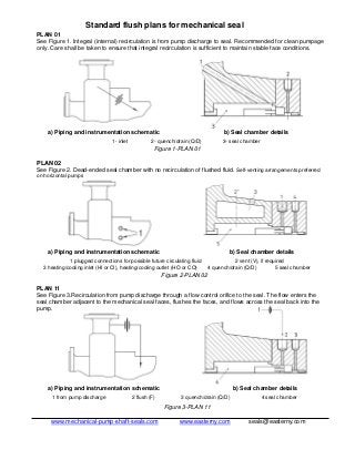
  • 1. Standard flush plans for mechanical seal PLAN 01 See Figure 1. Integral (internal) recirculation is from pump discharge to seal. Recommended for clean pumpage only. Care shall be taken to ensure that integral recirculation is sufficient to maintain stable face conditions. a) Piping and instrumentation schematic b) Seal chamber details 1- inlet 2- quench/drain (Q/D) 3- seal chamber Figure 1-PLAN 01 PLAN 02 See Figure 2. Dead-ended seal chamber with no recirculation of flushed fluid. Self-venting arrangements preferred on horizontal pumps a) Piping and instrumentation schematic b) Seal chamber details 1 plugged connections for possible future circulating fluid 2 vent (V), if required 3 heating/cooling inlet (HI or CI), heating/cooling outlet (HO or CO) 4 quench/drain (Q/D) 5 seal chamber Figure 2-PLAN 02 PLAN 11 See Figure 3.Recirculation from pump discharge through a flow control orifice to the seal. The flow enters the seal chamber adjacent to the mechanical seal faces, flushes the faces, and flows across the seal back into the pump. a) Piping and instrumentation schematic b) Seal chamber details 1 from pump discharge 2 flush (F) 3 quench/drain (Q/D) 4 seal chamber Figure 3-PLAN 11 www.mechanical-pump-shaft-seals.com www.easterny.com seals@easterny.com
  • 2. PLAN 12 See Figure 4. Recirculation from pump discharge through a strainer and flow control orifice to the seal. This plan is similar to Plan 11 but with the addition of a strainer to remove occasional particles. Strainers are not normally recommended because blockage of the strainer will cause seal failure. a) Piping and instrumentation schematic b) Seal chamber details 1 from pump discharge 2 flush (F) 3 quench/drain (Q/D) 4 seal chamber Figure 4-PLAN 12 PLAN 13 See Figure 5. Recirculation from pump seal chamber through a flow control orifice and back to the pump suction. a) Piping and instrumentation schematic b) Seal chamber details 1 to pump suction 2 flush (F) 3 quench/drain (Q/D) 4 seal chamber Figure 5-PLAN 13 PLAN 14 See Figure 6. Recirculation from pump discharge through a flow control orifice to the seal and simultaneously from the seal chamber through a control orifice (if required) to pump suction. This allows fluid to enter the seal chamber and provide cooling while continually venting and reducing the pressure in the seal chamber. Plan 14 is a combination of Plan 11 and Plan 13. a) Piping and instrumentation schematic b) Seal chamber details 1 to pump suction 2 from pump discharge 3 flush inlet (FI) 4 flush outlet (FO) 5 quench/drain (Q/D) 6 seal chamber Figure 6-PLAN 14 www.mechanical-pump-shaft-seals.com www.easterny.com seals@easterny.com
  • 3. PLAN 21 See Figure 7.Recirculation from pump discharge through a flow control orifice and cooler, then into the seal chamber. a) Piping and instrumentation schematic b) Seal chamber details 1 from pump discharge 2 flush (F) 3 quench/drain (Q/D) 4 seal chamber TI temperature indicator Figure 7-PLAN 21 PLAN 22 See Figure 8. Recirculation from the pump discharge through a strainer, a flow control orifice, and a cooler and into the seal chamber. Strainers are not normally recommended because blockage of the strainer will cause seal failure. a) Piping and instrumentation schematic b) Seal chamber details 1 from pump discharge 2 flush (F) 3 quench/drain (Q/D) 4 seal chamber TI temperature indicator Figure 8-PLAN 22 PLAN 23 See Figure 9. Recirculation from a pumping ring in the seal chamber through a cooler and back into the seal chamber. This plan can be used on hot applications to minimize the heat load on the cooler by cooling only the small amount of liquid that is recirculated. a) Piping and instrumentation schematic b) Seal chamber details 1 flush outlet (FO) 2 flush inlet (FI) 3 quench/drain (Q/D) 4 seal chamber 5 vent TI temperature indicator Figure 9-PLAN 23 www.mechanical-pump-shaft-seals.com www.easterny.com seals@easterny.com
  • 4. PLAN 31 See Figure 10. Recirculation from pump discharge through a cyclone separator delivering the clean fluid to the seal chamber. The solids are delivered to the pump suction line. a) Piping and instrumentation schematic b) Seal chamber details 1 from pump discharge 2 to pump suction 3 flush (F) 4 quench/drain (Q/D) 5 seal chamber Figure 10-PLAN 31 PLAN 32 See Figure 11. Flush is injected into the seal chamber from an external source. Care must be exercised in choosing a proper source of seal flush to eliminate potential for vaporization of the injected fluid and to avoid contamination of the fluid being pumped with the injected flush. a) Piping and instrumentation schematic b) Seal chamber details 1 from external source 2 flush (F) 3 quench/drain (Q/D) 4 seal chamber FI flow indicator PI pressure indicator TI temperature indicator Figure 11-PLAN 32 PLAN 41 See Figure 12. Recirculation from pump discharge through a cyclone separator delivering the clean fluid to a seal cooler and then to the seal chamber. The solids are delivered to the pump suction line. a) Piping and instrumentation schematic b) Seal chamber details 1 from pump discharge 2 to pump suction 3 flush (F) 4 quench/drain (Q/D) 5 seal chamber TI temperature indicator Figure 12-PLAN 41 www.mechanical-pump-shaft-seals.com www.easterny.com seals@easterny.com
  • 5. PLAN 51 See Figure 13. External reservoir providing a dead-ended blanket for fluid to the quench connection of the gland. a) Piping and instrumentation schematic b) Seal chamber details 1 reservoir 2 quench (Q) 3 drain (D), plugged 4 flush (F) 5 seal chamber Figure 13-PLAN 51 PLAN 52 See Figure 14. External reservoir providing buffer liquid for the outer seal of an Arrangement 2 seal. During normal operation, circulation is maintained by an internal pumping ring. The reservoir is usually continuously vented to a vapour recovery system and is maintained at a pressure less than the pressure in the seal chamber. a) Piping and instrumentation schematic b) Seal chamber details 1 to collection system 2 reservoir 3 make-up buffer fluid 4 flush (F) 5 liquid buffer outlet (LBO) 6 liquid buffer inlet (LBI) 7 seal chamber LSH level switch high LSL level switch low LI level indicator PI pressure indicator PSH pressure switch high a Items above this line are the responsibility of the purchaser; items below this line shall be supplied by the vendor. b Normally open. c If specified. Figure 14-PLAN 52 www.mechanical-pump-shaft-seals.com www.easterny.com seals@easterny.com
  • 6. PLAN 53A See Figure 15. Pressurized external barrier fluid reservoir supplying clean fluid to the seal chamber. Circulation is by an internal pumping ring. Reservoir pressure is greater than the process pressure being sealed. a) Piping and instrumentation schematic b) Seal chamber details 1 from external pressure source 2 reservoir 3 make-up barrier fluid 4 flush (F) 5 liquid barrier outlet (LBO) 6 liquid barrier inlet (LBI) 7 seal chamber LSH level switch high LSL level switch low LI level indicator PI pressure indicator PSL pressure switch low a Items above this line are the responsibility of the purchaser; items below this line shall be supplied by the vendor. b Normally open. c If specified. Figure 15-PLAN 53A PLAN 53B See Figure 16. External piping provides fluid for the outer seal of a pressurized dual seal arrangement. Pre-pressurized bladder accumulator provides pressure to the circulation system. Flow is maintained by an internal pumping ring. Heat is removed from the circulation system by an air-cooled or water-cooled heat exchanger. a) Piping and instrumentation schematic b) Seal chamber details 1 make-up barrier fluid 2 bladder accumulator 3 bladder charge connection 4 flush (F) 5 liquid barrier outlet (LBO) 6 liquid barrier inlet (LBI) 7 seal chamber 8 vent PI pressure indicator PSL pressure switch low TI temperature indicator Figure 16-PLAN 53B www.mechanical-pump-shaft-seals.com www.easterny.com seals@easterny.com
  • 7. PLAN 53C See Figure 17. External piping provides fluid for the outer seal of a pressurized dual seal arrangement. Reference line from the seal chamber to a piston accumulator provides pressure to the circulation system. Flow is maintained by an internal pumping ring. Heat is removed from the circulation system by an air-cooled or water-cooled heat exchanger. a) Piping and instrumentation schematic b) Seal chamber details 1 make-up barrier fluid 2 piston accumulator 3 flush (F) 4 liquid barrier outlet (LBO) 5 liquid barrier inlet (LBI) 6 seal chamber 7 vent LI level indicator LSL level switch low PI pressure indicator PRV pressure relief valve PSL pressure switch low TI temperature indicator Figure 17-PLAN 53C PLAN 54 See Figure 18. Pressurized external barrier fluid reservoir or system supplying clean fluid to the seal chamber. Circulation is by an external pump or pressure system. Reservoir pressure is greater than the process pressure being sealed. a) Piping and instrumentation schematic b) Seal chamber details 1 from external source 2 to external source 3 flush (F) 4 liquid barrier outlet (LBO) 5 liquid barrier inlet (LBI) 6 seal chamber Figure 18-PLAN 54 www.mechanical-pump-shaft-seals.com www.easterny.com seals@easterny.com
  • 8. PLAN 61 See Figure 19. Tapped and plugged connections for the purchaser’s use. Typically this plan is used when the purchaser is to provide fluid (such as steam, gas, or water) to an external sealing device. a) Piping and instrumentation schematic b) Seal chamber details 1 quench (Q), plugged 2 drain (D), plugged 3 flush (F) 4 seal chamber Figure 19-PLAN 61 PLAN 62 See Figure 20.Exterior source providing a quench. The quench may be required to prevent solids from accumulating on the atmospheric side of the seal. Typically used with a close-clearance throttle bushing. a) Piping and instrumentation schematic b) Seal chamber details 1 quench (Q) 2 drain (D) 3 flush (F) 4 seal chamber Figure 20-PLAN 62 PLAN 65 See Figure 21. External drain piping is arranged to alarm on high seal leakage, measured by a float type level switch. The orifice downstream of the level switch is typically 5 mm (0,25 in) and is located in a vertical piping leg. a) Piping and instrumentation schematic b) Seal chamber details 1 to liquid collection system 2 flush (F) 3 quench (Q), plugged 4 drain (D) 5 seal chamber LSH level switch high Figure 21-PLAN 65 www.mechanical-pump-shaft-seals.com www.easterny.com seals@easterny.com
  • 9. PLAN 71 See Figure 22. Tapped connections for purchaser’s use. Typically, this plan is used when the purchaser may use buffer gas in the future. a) Piping and instrumentation schematic b) Seal chamber details 1 flush 2 containment seal vent (CSV), plugged 3 containment seal drain (CSD), plugged 4 gas buffer inlet (GBI), plugged 5 seal chamber Figure 22-PLAN 71 PLAN 72 See Figure 23. Externally supplied gas buffer for Arrangement 2 seals. Buffer gas may be used alone to dilute seal leakage or in conjunction with Plan 75 or 76 to help sweep leakage into a closed collection system. Pressure of buffer gas is lower than the process-side pressure of inner seal. a) Piping and instrumentation schematic b) Seal chamber details 1 buffer gas panel 2 flush (F) 3 containment seal vent (CSV) 4 containment seal drain (CSD) 5 gas buffer inlet (GBI) 6 seal chamber FE flow meter (magnetic type shown) FIL coalescing filter, used to ensure solids and/or liquids which might be present in buffer gas do not contaminate seals PCV pressure control valve, used to limit buffer gas pressure to prevent reverse pressurization of inner seal and/or limit pressure applied to containment seal PI pressure indicator PSL pressure switch low FSH flow switch high a If specified. b Items to the left of this line shall be supplied by the vendor; items to the right are the responsibility of the purchaser. Figure 23-PLAN 72 www.mechanical-pump-shaft-seals.com www.easterny.com seals@easterny.com
  • 10. PLAN 74 See Figure 24. Externally supplied barrier gas used to positively prevent process fluid from leaking to atmosphere. Pressure of barrier gas is higher than process side of inner seal. Venting of the seal chamber may be required prior to start-up and operation to avoid the collection of gas in the pump. a) Piping and instrumentation schematic b) Seal chamber details 1 gas barrier panel 2 vent (if required) 3 gas barrier outlet (normally closed), used only to depressurize seal chamber 4 gas barrier inlet 5 seal chamber FE flow meter FIL coalescing filter, used to ensure solids and/or liquids which might be present in barrier gas do not contaminate seals FSH flow switch high PI pressure indicator PCV pressure control valve, set pressure above process side of inner seal PSL pressure switch low a Items to the left of this line shall be supplied by the vendor; items to the right are the responsibility of the purchaser. b If specified. Figure 24-PLAN 74 PLAN 75 See Figure 25. Containment seal chamber drain for condensing leakage on Arrangement 2 seals. This plan is used when pumped fluid condenses at ambient temperatures. System is supplied by vendor. a) Piping and instrumentation schematic b) Seal chamber details 1 to vapour collection system 2 to liquid collection system 3 test connection 4 flush (F) 5 containment seal vent (CSV), plugged 6 containment seal drain (CSD) 7 gas buffer inlet (GBI) 8 seal chamber LI level indicator LSH level switch high PSH pressure switch high PI pressure indicator b Items above this line are the responsibility of the purchaser; items below this line shall be supplied by the vendor. Figure 25-PLAN 75 www.mechanical-pump-shaft-seals.com www.easterny.com seals@easterny.com
  • 11. PLAN 76 See Figure 26. Containment seal chamber drain for non-condensing leakage on Arrangement 2 seals. This plan is used when pumped fluid does not condense at ambient temperatures. System is supplied by the vendor. Tubing shall be 13 mm (1/2 in) minimum diameter and shall rise continuously from the CSV connection to the piping /instrumentation harness. The harness shall be pipe of minimum size DN 15 (NPS 1/2). Harness shall be supported from overhead structure or side stand such that no strain is put on tubing connected to seal gland. a) Piping and instrumentation schematic b) Seal chamber details 1 to vapour recovery system 2 tube, see below 3 pipe, see below 4 flush (F) 5 containment seal vent (CSV) 6 containment seal drain (CSD) 7 gas buffer inlet (GBI) 8 seal chamber PI pressure indicator PSH pressure switch high a Items above this line are the responsibility of the purchaser; items below this line shall be supplied by the vendor. Figure 26-PLAN 76 www.mechanical-pump-shaft-seals.com www.easterny.com seals@easterny.com