1. 2 SITE ANALYSIS AND SET-UP
The physical characteristics of the site and its immediate environment will influence the decisions to be
made about a building's design and construction. The information gathered from a thorough site analysis is,
therefore, a vital exercise and must be completed before any design or construction work commences. This
information can then be collated in a performance appraisal document from which informed decisions about
the best way to proceed may be made.
2.1 FUNCTION OF THE SITE ANALYSIS
Prior to any construction operations, the client/developer will want to know whether it is economically viable
to build on the proposed site. Because the nature and condition of the ground and soil below the surface of
the site are an unknown quantity they pose a considerable risk to the construction project, with the potential
to cause delays and additional costs, both of which can be substantial. Inadequate soil investigation and
hence inappropriate foundation design can lead to structural problems at a later date, which is a problem
for the building owners and users as well as the building insurers.
Many projects are built on brownfield sites (land that has been previously built on and used) and it may be
necessary to seal, stabilise or remove any contaminated ground, toxic waste or other dangerous
substances before commencing the main construction works. The extent of contamination must be
established before any work commences on the site.
The main purpose of site analysis is to identify and hence reduce the risks associated with the development
by recording site features and soil characteristics, helping to determine the design and cost of suitable
foundations and structure. A thorough site analysis is an essential first step that will assist development,
design and construction decisions. The site analysis helps:
The client to assess whether the project is viable (best done in consultation with professional advisors)
The client, designer, structural engineer and contractor to locate the best position for the building,
avoiding or accommodating identified problems where possible, while making the best possible use of
physical features and environmental conditions
The engineers to design the most suitable foundation system
The mechanical and electrical consultants to design the service provision
The designers and contractor to ensure that safe construction methods are used
The environmental consultants to identify the most suitable way of dealing with any contaminants and
problem materials, e.g. remediation works, material reuse, on-site treatment and disposal options
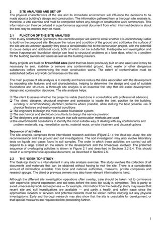
Sequence of activities
The site analysis comprises three interrelated research activities (Figure 2.1); the desk-top study, the site
reconnaissance and the ground and soil investigations. The soil investigation may also involve laboratory
tests on liquids and gases found in soil samples. The order in which these activities are carried out will
depend to a large extent on the nature of the development and the timescales involved. The preferred
sequence of overlapping activities is shown in Figure 2.1 and described in Sections 2.2-2.4. This should
result in a comprehensive appraisal document, as described in Section 2.5.
2.2 THE ‘DESK-TOP STUDY
The 'desk-top study' is a vital element in any site analysis exercise. The study involves the collection of all
documents and materials that can be obtained without having to visit the site. There is a considerable
amount of information available from local and national authorities, museums, private companies and
research groups. The client or previous owners may also have relevant information to hand.
Although the different site investigation operations often overlap, care should be taken not to commence
with expensive ground exploration and soil tests before the desk-top study is completed. This is partly to
avoid unnecessary work and expenses — for example, information from the desk-top study may reveal that
recent site and soil investigations are available — and partly a health and safety issue since the
approximate location of services and potential hazards must be known before carrying out any physical
investigations. Early and thorough research may also show that the site is unsuitable for development, or
that special measures are required before proceeding further.
1
2. Information required
Ownership(s) and legal boundaries
The client should provide, via a legal representative, information pertaining to the exact location of the site
boundaries and responsibilities for maintaining them. These will need to be checked against a measured
survey and any areas of uncertainty checked by the legal representative. Other issues to be determined by
the client's legal representative include:
Rights of way
Rights of light
Rights of support (for adjoining properties)
Legal easements
Ownership of land (essential where parcels of land are being assembled to make a larger site)
Rights of tenants, etc.
Ground conditions
As a first step it is usual to collect information on soil and subsoil conditions from the county and local
authority. This includes knowledge from maps, geological surveys, aerial photography and works for
buildings and services adjacent to the site, which may in itself give an adequate guide to subsoil conditions.
Geological maps from the British Geological Survey, information from local geological societies, Ordnance
Survey maps, mining, river and coastal information may also be useful.
Services
All suppliers of services should be contacted to confirm the position of pipes and cables and the nature of
the existing supply, i.e. its capacity. This includes gas, mains water, sewage and surface drainage pipes as
well as electricity, broadband and telephone cables. It is usual for a representative of the supplier to visit
the site to identify their equipment (which might be in a different location to that shown on plans).
Contaminated land and methane
Previous use of land can give some clues as to the likely contaminants to be found and the local authority
may have records that can help in this regard. However, extensive soil testing should be carried out to
ascertain the nature and extent of any contamination. Methane is associated with landfill sites, and local
knowledge about the position of old tips/landfill can prove useful at an early stage.
Radon
In certain areas of the UK, radon gas occurs naturally within the underlying ground and poses a health
threat to the inhabitants of buildings. Local authorities provide advice on the likely level of contamination
and will advise on the extent of protection required to prevent the radon gas from entering the building.
2
3. Flooding
Damage to property and possessions and the associated disruption to businesses and family life has
become a serious concern in recent years as the frequency of flooding has increased. Factors include
heavy rainfall, buildings sited on, or too close to, flood plains and inadequate maintenance of rivers and
watercourses. Thorough checks should be made about previous flooding of the site (if any), proximity to
flood plains and any special requirements suggested or required by the various authorities and insurers.
Typical sources of information
Information will always be site-specific; however, the following list of information sources serves as a
general guide:
Ordnance Survey — detailed maps in many different formats are available from Ordnance Survey,
Romsey Road, Southampton S016 4GU (www.ordnancesurvey.co.uk)
Historical maps (www.old-maps.co.uk) and libraries local to the site
Geological maps — the British Geological Survey is the national repository for geosciences data in
the UK. Information provided includes maps, records and materials, including borehole cores and
specimens from across the UK. Address: London Information Office, British Geological Survey,
Earth Galleries, Natural History Museum, Exhibition Road, London SW7 2DE (www.bgs.ac.uk)
Hydrogeological maps — soil reports and publication lists are obtainable from soil sur-
vey and Land Research Centre, Cranfield University, Silsoe, Bedford MK 45 4DT
Meteorological information — monthly and annual reports are available on air temperature, wind
speed, rainfall and sunshine. Such information is useful when designing the building and for
scheduling construction operations. Statistics on averages and extremes are also available. The
Met Office, Room JG6, Johnson House, London Road, Bracknell, Berks RG12 2SY
(www.metoffice.gov.uk)
Hydrological information — surface water run-off data are collected by water authorities, private
water undertakings and local authorities
Site history:
Previous owners and developers
Site surveys and drawings used for previous development
Records held by Building Control
Local newspaper archives
Records held by the local planning authority
Gas supplier — location of gas mains
Electricity supplier — location of electricity cables
Electricity generating board — mains electricity cables
Water suppliers — water supply mains
Mains sewers
Local authority — local sewers
Telecommunications authority — telephone and optical cables
Rail authority — railways
British Water Board — canals
British coal — underground working building inspector
Aerial photographs — there are many collections of aerial photographs dating back over many decades.
A directory of organisations and agencies that hold aerial photographs can be obtained from Publications
Department, Aslib, The Association for Information Management, Information House, 20-24 Old Street,
London EC1V 9AP
2.3 SITE RECONNAISSANCE
Written approvals from the client and/or the property owners must be in place and a thorough risk
assessment exercise must be carried out before entering the site, especially before any invasive
investigations are carried out (which may require separate written permission). Obvious considerations are
related to trespass and criminal damage, although the prime concern must be for the safety of those doing
the investigations. The majority of sites will have been used previously (and may still be in use) and might
contain buildings that are structurally unsound (which may be redundant or still in use despite their
condition). Specialists should be appointed to establish the condition and safety of existing structures and
whether or not asbestos is present. Figure 2.2 provides an overview of the type of information that can be
3
4. collected during a site reconnaissance.
The visual inspection of the site
A visit to the site and its surroundings should always be made to record everything relevant to the proposed
development. The site reconnaissance is often referred to as the visual inspection or the `walkover. From
experience we have found that two pairs of eyes (or more) are always better than one and so the visual
inspection should be undertaken by at least two, and preferably three, people, e.g. the architect, engineer
and contractor, with each taking their own notes but discussing features as they come across them. Careful
observation should be made of the nature of the subsoil, vegetation, evidence of marshy ground, signs of
groundwater and flooding, irregularities in topography, ground erosion and ditches and flat ground near
streams and rivers where there may be soft alluvial soil. A record should be made of the foundations of old
buildings on the site. Cracks and other signs of movement in adjacent buildings should be noted. When
undertaking site reconnaissance on contaminated land, ensure as far as possible that all hazards have
been identified and that correct safety procedures are followed. In preparation for the site reconnaissance,
all of the maps and records should be assembled so that any differences or omissions found when walking
over and observing the site can be recorded. A visual inspection of physical site boundaries should be
made and compared with any legal documents that show boundaries.
British Standard procedure for walkover surveys
When conducting a walkover survey, the British Standard for site investigations BS 5930:1999) suggests
that the surveyor should:
Traverse the whole area on foot (if possible and safe to do so)
Establish the proposed location of work on plans
Identify and record any differences on the plans and maps
Record details of existing services, trees, structures, buildings and obstructions
4
5. Check access and determine capability of sustaining heavy construction traffic
Record water levels, fluctuations in levels, direction of flow and flow rate
Identify adjacent property and the likelihood of it being affected by proposed works
Identify any previous or current activities that may have led to contamination
Record mine or quarry workings, old structures and other features
Record obvious features that pose immediate hazard to public health and safety or the environment
Record any areas of discoloured soil, evidence of gas production or underground combustion
Identification and physical location of services
Before undertaking any digging, e.g. for trail holes, it is necessary to clearly identify the nature of the
services on the site and their actual position. Unfortunately, the majority of the plans provided by the
services providers only give an approximate location of their pipes and cables; therefore, some detective
work is required on site. The first task is to identify all inspection covers and the nature of the service, and
compare their positions with those on the drawings. Handheld sonic and magnetic detecting devices to help
locate the position of services are available from most plant hire firms. Exact position and depth can be
established by carefully hand digging trial pits to expose pipes, cables and conduits. The service providers
will also be keen to establish exact positions in an attempt to prevent damage to their pipes and cables.
The organisations responsible for particular services should be invited to the site to help to establish the
exact position, size and capacity of their supply and to resolve any uncertainty.
In order to develop the site to its full potential services may need to be re-routed, if the appropriate authority
will give permission. This is usually an expensive option, which could threaten the viability of the project.
Alternatively, the proposed position of the building may need to be adjusted to enable the project to
proceed without undue disruption to major service routes.
Surveys
Measured survey
A land surveyor should conduct a topographical survey to establish the physical boundaries, existing
features and variations in level. Most land surveyors have a standard list of features to be established
during the land survey, although it is not uncommon to direct the land surveyors to particular areas to
record additional information.
Condition survey
Condition surveys are used to record the condition of boundaries and adjoining property prior to work
commencing. Condition surveys are also employed to record the state of existing buildings on the site that
are to be protected, refurbished or altered. Before commencing any work that is likely to result in vibration
(e.g. demolition, excavations, piling, heavy construction traffic, and so on) it is important to undertake a full
condition survey of surrounding and adjoining properties and structures. This serves as a record for any
subsequent claims for damage and also serves as a good source of design information, for example,
indicating how particular materials have weathered. Detailed drawings and written descriptions of the
property should be supported with photographic evidence.
Photographic and video surveys
Photographic and video surveys are useful tools to prompt one's memory when back in the office. They
also provide a record of the original condition of the site and adjoining land/property in case of any dispute
or claim for damage. Photographic surveys should be conducted in a systematic and thorough manner, with
the position of the photographer and direction of view noted on a site plan to avoid any future confusion.
2.4 SOIL INVESTIGATIONS
Details of the subsoil should include soil type, consistency or strength, soil structure, moisture conditions
and the presence of roots. From the nature of the subsoil the bearing capacity, seasonal volume changes
and other possible ground movements are assumed. To determine the nature of the subsoil below
foundation level it is necessary either to excavate trial pits some depth below the assumed foundation level
or to bore in the base of the trial hole to withdraw samples.
The common methods of obtaining samples include:
5
6. Trial pits
Boreholes — Cable percussive boreholes and rotary drilled borehole
Window sampling and dynamic probe testing
When proposing work to existing buildings (e.g. adding another floor) it will be necessary to expose the
existing foundation in a number of places to check if it was built as detailed on drawings (if available) and
also to check the subsoil below the foundation. Whichever system is adopted will depend on economy, the
proposed building works and the nature of the subsoil. Trial pits or boreholes should be sufficient in number
to determine the nature of the subsoil over and around the site of the building and should be at most, say,
30 m apart.
Ground movements that may cause settlement are:
Compression of the soil by the load of the building
Seasonal volume changes in the soil
Mass movement in unstable areas such as made up ground and mining areas where there may be
considerable settlement
Ground made unstable by adjacent excavations or by de-watering, for example, due to an adjacent
road cutting.
Trial pits
To make an examination of the subsoil trial pits and/or boreholes are excavated. Trial pits are usually
excavated by a mechanical excavator, or in some cases by hand tools, to a depth of 3-4 m. The nature of
the subsoil is determined by examination of the sides of the excavations. Soil and rocks can be examined
in situ on the faces of the excavated pit, and samples taken for further laboratory tests. The trial pit also
provides an indication of the ease of dig (or excavation), trench stability and groundwater conditions. For
exploration of shallow depths (up to 3 m) this is usually more economical than boreholes. The pits are
usually rectangular, being approximately 1.2 X 1.2 m in plan. The pits should be excavated in the vicinity of
the proposed structure; if the pit is located under a proposed foundation particular attention needs to be
given to the material used to backfill the hole. In such situations material should be of sufficient strength
and well compacted. As each trial pit is excavated and inspected a report should be made of the inspection.
Typical information contained in the inspection, the trial pit log, is shown in Figure 2.6.
Boreholes
`Borehole' is often used as a generic term that represents the various methods used to excavate and
extract disturbed and undisturbed soil samples. All samples taken from bore-holes should be sealed as
soon as possible to minimise any loss of moisture before testing. Some of the most commonly used
methods are as follows.
Auger boring — rotary boring methods
These holes are usually made by hand or powered auger into the ground. Auger holes are typically 75-150
mm in diameter. Short helical augers are used and disturbed samples of soil are collected as they are
brought to the surface. Such methods are not widely used as they do not allow the soil to be examined in
situ and are not capable of penetrating to the depth of boreholes. Rotary drilling is used where the
boreholes are being cut into very dense gravel or bedrock. Samples or bedrock are recovered in seamless
plastic tubes, are logged by and engineer, and then taken for laboratory testing (Photograph 2.1).
6
7. Window samplers
A window sampler is a steel tube about 1 m long with a hole cut into the wall of the tube allowing the
disturbed sample to be viewed or soil samples taken from the tube. The tube is driven into the ground using
a lightweight percussion hammer and extracted with the aid of jacks. A range of tube diameters are
available. In practice the large tubes are driven in first and removed leaving a hole for smaller tubes to be
inserted and driven in further. Samples can be obtained down to a depth of 8 m.
7
8. Window sampling can be carried out using either handheld pneumatic samplers or tracked percussive
samplers (Photograph 2.2). The samples are retrieved in seamless plastic tubes. A qualified engineer logs
the samples (Photograph 2.3). Window sampling is suited to sites with restricted access, where disturbance
is to be kept to a minimum and contamination investigation. The percussive samplers are also normally
capable of doing penetrometer testing. Penetrometer testing is a continuous soil test procedure which ena-
bles the relative density or strength of the ground to be determined. Further information can be found at the
Structural Soils website, www.soils.co.uk.
8
9. Ground and soil tests
There are a wide variety of on-site and laboratory tests that can be used to establish the characteristic
ground and soil conditions. The extent of soil investigation will be based on the nature of the building and
characteristics of the site. More detailed site and laboratory studies will provide more information, reducing
the risks inherent in building on unknown ground. Laboratory and on-site tests that can be used include:
On-site test
Plate load test
Vane shear test
California bearing ratio (CBR) test
Dry density/moisture relationship
SPT (Standard Penetration Test)
Lightweight dynamic penetrometers
Cone penetration tests (CPT)
Methane/oxygen/carbon dioxide/barometric pressure test
Laboratory work
Triaxial compression tests
Liquid and plastic limit tests
Sieve analysis — particle size and distribution
Moisture content
pH value tests
2.6 SITE SET-UP AND SECURITY
Site planning is important, especially for sites with limited space and/or those located in busy areas.
Although this is usually covered under the literature on construction management a brief summary of the
main issues to be considered are presented here.
Site set-up
Access
Access to the site is required for personnel, construction plant and delivery vehicles during construction.
Firefighting equipment must also have clear access in case of a fire or emergency occurring during the
works. Temporary vehicular access may be allowed in consultation with the appropriate Highways, Police
and Town Planning departments. Safe access for large cranes and wide, heavy and/or long loads will also
need careful planning.
9
10. Storage and waste
Materials and plant must be stored so as to protect them from the weather and from damage from site
operations. This applies equally to materials stored on site for a short period and those stored for a longer
period. Space for the construction and subsequent protection from damage of sample panels is a related
consideration. The reduction of waste on site is linked to good site management and to good detailing.
When detailing a building, attention should be given to reducing the amount of cutting and hence waste
generated on the site (which is expensive to dispose of).
Services and accommodation
As a minimum a suitable, metered supply of electricity and water will be required; so too will foul drainage.
Site personnel require office space and comfort facilities. These are usually provided in specialist
prefabricated site units that are hired by the contractor for the duration of the project. The well-being of
construction workers and also visitors to the site is an important factor.
Security and safety
Site security is required for two reasons. First, to protect the materials and plant left on the site overnight
from theft and malicious damage. Second, to stop members of the public from inadvertently wandering on
to the site and hence endangering their safety. Perimeter fencing must be secure and all access points
monitored. In addition to fencing and physical barriers to unauthorised entry, many contractors also employ
security firms to provide additional protection at night and at weekends. Monitoring of materials entering
and leaving the site is also required to prevent pilfering by site workers.
Levelling and setting out
Once all of the information on the site has been collected, appropriate levels and positions for the buildings
must be established. To determine a level for the building it is necessary to find the levels and gradients of
the land, the amount of material that will need to be removed, e.g. unstable or degradable material such as
topsoil and waste. Once the lie of the land is mapped out then the loadbearing strata on which the
foundations and ground floor construction will bear is determined. In most cases the ground floor level is
positioned slightly higher than the existing ground level. By positioning the floor level above the external
ground level unnecessarily deep excavation is avoided and problems of groundwater penetration are
reduced.
Setting out for excavation and construction
Once the contractor has obtained legal possession of the site, and has made the site safe and secure, the
land must be taken down to workable levels. Building and grid lines should be set out and before any work
can commence a temporary benchmark should be established. Temporary benchmarks will provide a fixed
level on the site. All other levels for footings, floor levels, road levels, etc. can be determined by working out
the difference in levels from the temporary benchmark.
In order to establish the on-site temporary benchmark a fixed reference point off-site needs to be found, i.e.
Ordnance Survey record benchmarks that have been established on existing structures. Benchmarks can
often be found on churches, bridges and other large structures (and should be shown on the land
surveyor's drawings). Once the level has been found it can be transferred to site. Site-based temporary
benchmarks should be placed on a sturdy structure in positions where they are not liable to be knocked or
disturbed. The benchmark should be recorded on a site plan for reference during construction.
Reference points on the ground also need to be determined to position the building and associated works
correctly. North- and east-based coordinates are used to position grid lines; these may be obtained using a
GPS (global positioning system) or using two reference points with known coordinates. Alternatively, the
building or grid lines can be simply set out off existing structures.
Reduced level dig
Once a level has been established and grid lines or building lines marked out the reduce level dig can
commence. Generally, areas of the site where major excavation will take place are reduced. Under
buildings the reduced level dig is excavated to the underside level of the floor construction; this is the
largest volume of excavation that should take place. Reducing the level of the site where buildings are
positioned helps to provide a level site for ease of work. Foundations that go deeper than the underside of
the floor construction are excavated independently from this level.
10
11. 2.7 SITE WORKS AND SETTING OUT
When a builder is given possession of a building site the contractor will have been provided with the site
layout plan and the detail drawings necessary for him to construct the building(s). Under most forms of
building contract it is the builder's responsibility to see that the setting out is accurate.
The site having been taken over, the task of preparing for and setting out the building can be commenced.
These operations can be grouped under three headings:
• clearing the site;
• setting out the building;
• establishing a datum level.
Clearing the site
This may involve the demolition of existing buildings, the grubbing out of bushes and trees, and the removal
of soil to reduce levels. Demolition is a skilled occupation and should be tackled only by an experienced
demolition contractor. The removal of trees can be carried out by manual or mechanical means. The
removal of large trees should be left to the specialist contractors.
Building Regulation Cl, `The ground to be covered by the building shall be reasonably free from vegetable
matter.' This is in effect to sterilise the ground, because the top 300 mm or so will contain plant life and
decaying vegetation. This means that the topsoil is easily compressed and would be unsuitable for
foundations. Topsoil is valuable as a dressing for gardens, and will be retained for reinstatement when the
site is landscaped. The method chosen for conducting the site clearance work will be determined by the
scale of development, and by consideration for any adjacent buildings.
11
12. Setting out the site
The first task is to establish a baseline from which the whole of the building can be set out. The position of
this line must be clearly marked on-site so that it can be re-established at any time. For on-site measuring a
steel tape should be used (30 m would be a suitable length). Linen and plastic-coated tapes are also
available. The disadvantage with linen tapes is that they are liable to stretch.
After the baseline has been set out, marked and checked, the main lines of the building can be set out,
each corner being marked with a stout peg. A check should now be made of the setting-out lines for right
angles and correct lengths. There are several methods of checking whether a right angle has been
established, and in fact the setting out would have been carried out by one of these methods. A check must
still be made, and it is advisable to check by a different method to that used for the setting out. The
setting-out procedure and the methods of checking the right angles are illustrated in Fig. 1.1.1.
After the setting out of the main building lines has been completed and checked, profile boards are set up
as shown in Fig. 1.1.2. These are set up clear of the foundation trench positions to locate the trench,
foundations and walls. Profile boards are required at all trench and wall intersections.
Establishing a datum level
It is important that all levels in a building are taken from a fixed point called a datum. This point should now
be established; wherever possible it should be related to an ordnance benchmark. This is an arrow with a
horizontal mark above the arrow as shown in Fig. 1.1.3. The centreline of the horizontal is the actual level
12
13. indicated on an Ordnance Survey map. Benchmarks are found cut or let into the sides of walls and
buildings. Where there are no benchmarks on or near the site, a suitable datum must be established. A site
datum or temporary benchmark could be a post set in concrete or a concrete plinth set up on site. ,
Taking levels
The equipment used is an engineer's level and a levelling staff. The level is simply a telescope fitted with
cross-hairs to determine alignment. The telescope rotates on a horizontal axis plate, mounted on a tripod.
The staff is usually 4 m long in folding or extendable sections. The `E' pattern shown in Fig. 1.1.4 is
generally used, with graduations at 10 mm intervals. Some staffs may have 5 mm graduations. Readings
are estimated to the nearest millimetre.
Levelling commences with a sight to a benchmark from the instrument stationed on firm ground. Staff
stations are located at measured intervals such as a 10 m grid. From these, instrument readings are taken
as shown in Fig. 1.1.5. The level differentials can then be combined with plan area calculations to
determine the volume of site excavation or cut and fill required to level the site.
From Fig. 1.1.5:
Rise and fall method:
Staff reading at A = 2.500 m Staff reading at B = 0.750 m
Ground level at A = 100 m above ordnance datum (AOD)
Level at B = 100 m + rise (— fall if declining)
Level at B = 100 m + (2.500 — 0.750) = 101.750 m.
Alternative height of collimation (HC) method: HC at A = Reduced level (RL) + staff reading
= 100 m + 2.500 = 102.500 (AOD) Level at B = HC at A — staff reading at B
= 102.500 — 0.750 = 101.750 m
13
14. Measuring angles
The sitesquare shown in Fig. 1.1.1 is accurate for determining right angles in the horizontal plane. Where
acute or obtuse angles occur in the horizontal, or vertical angles are to be established or checked, a
theodolite is used. This instrument is basically a focusing telescope with cross-hairs, mounted on horizontal
index plates over a tripod. A vertical measurement circle with index is attached to one side of the telescope.
Figure 1.1.6 shows the outline features of a traditional vernier theodolite. Traditional theodolites require
visual or manual measurement of angles on the micrometer index or scale. In contrast, contemporary
instruments are far more sophisticated, with automatic settings, liquid crystal displays, and facilities for data
14
15. transfer to computers.
With the instrument firmly stationed, the telescope and horizontal (vertical if appropriate) plate are rotated
from an initial sighting through the required angle. A pole-mounted target may be used for location. A check
can be made by rotating the telescope through 1800 vertically and the index through 180° horizontally for a
second reading. Angles are recorded in degrees, minutes and seconds, the extent of accuracy determined
by the quality of instrument and the skill of the user.
Sloping sites
Very few sites are level, and therefore before any building work can be commenced the area covered by
the building must be levelled. In building terms this operation is called reducing levels. Three methods can
be used, and it is the most economical that is usually employed.
Cut and fill - The usual method because, if properly carried out, the amount of cut will equal the
amount of fill.
Cut - This method has the advantage of giving undisturbed soil over the whole of the site, but has
the disadvantage of the cost of removing the spoil from the site.
Fill - A method not to be recommended because, if the building is sited on the filled area, either
deep foundations would be needed or the risk of settlement at a later stage would have to be
accepted. The amount of fill should never exceed a depth of 600 mm.
The principles of the above methods are shown in Fig. 1.1.7.
15