SlideShare une entreprise Scribd logo
1  sur  43
Télécharger pour lire hors ligne
i
Preface
This is report about three months Industrial Training session at ITSMS PVT Ltd,
Malabe. Training report is related with the BTEC HND in Electrical & Electronic
Engineering at ICBT Campus, Mount Lavinia. This report included details of training
establishment, company overview, and services provided by the company in the
chapter 1. In chapter 2, trainee’s experiences, works involved, projects done,
individual activities, industrial experiences gained and skills build are included.
Chapter 3 is reserved for the conclusion.
How Industrial training is helped to improve trainee’s attributions and skills is
discussed here with trainee’s experiences. Basically many activities related to the
telecommunication field such as, link planning, link budget calculating, LOS
calculation, field surveys, link installations, software and hardware upgrading are
discussed here clearly with well-structured manner
ii
Acknowledgement
First of all I would like to pay my gratitude and sincerity to my parents. I am in this
position thanks to their striving effort where they try to make my future a success.
I would like to thank the All the lecturers of Electrical & Electronic section
especially, Mr. Ruwan Fernando for his great contribution in following my training
session as well.
Special thanks to the Project Manager of the ITSMS Engineering division Mr. E.W
Disanayake and General Manager Eng. Nuwan Anuradha for welcoming us to the
company and guiding me throughout the project and for his sincere dedication to
grant us a good training at the division. Special thanks to Mr. Roshan Beliketimulla,
(Manager - Finance). Thank you very much for your kind cooperation.
I offer my special thanks to all the Engineers, technical officers and other staff who
has contributed to make our training a success.
In addition, I must thank all trainees for their wonderful corporation & understanding
during the training.
Thank you.
iii
Table of Content
Preface.........................................................................................................................i
Acknowledgement......................................................................................................ii
Table of Content....................................................................................................... iii
Table of figures .........................................................................................................iv
CHAPTER 1 ..................................................................................................................1
Introduction to the Training Establishment................................................................1
1.1 Introduction ......................................................................................................1
1.2 ITSMS Vision & Mission.................................................................................2
1.3 Services.............................................................................................................2
CHAPTER 2 ..................................................................................................................9
Training Experiences .....................................................................................................9
Establishing a new link ..............................................................................................9
Mobile Site Planning ..............................................................................................9
OUTDOOR UNITS..............................................................................................15
INDOOR UNITS..................................................................................................24
Radio Base Station................................................................................................27
RTN600 series upgrading.........................................................................................29
CHAPTER 3 ................................................................................................................34
Conclusion ...................................................................................................................34
Abbreviations ...........................................................................................................36
References ................................................................................................................38
iv
Table of figures
Figure 1. 1: Weblct2000 screenshot for link configuration ...........................................3
Figure 1. 2: Training Establishment...............................................................................5
Figure 1. 3: At the top of Lanka bell tower, Seeduwa...................................................6
Figure 1. 4: While testing 1.2m Microwave antenna connections.................................6
Figure 1. 5: While setting RRU (Remote Radio Unit)...................................................7
Figure 1. 6: At a Link installation..................................................................................7
Figure 2. 1: Line of sight phenomena ..........................................................................10
Figure 2. 2: A guy tower..............................................................................................13
Figure 2. 3: 30m Mobile tower ....................................................................................14
Figure 2. 4: A Remote Radio Unit (RRU)...................................................................16
Figure 2. 5: 0.6m Microwave antenna .........................................................................17
Figure 2. 6: Microwave antenna with ODU.................................................................18
Figure 2. 7: Antenna bracket with angle indicator.......................................................21
Figure 2. 8: A single Band Antenna.............................................................................22
Figure 2. 9: A dual band antenna.................................................................................23
Figure 2. 10: A DUDU in BTS....................................................................................26
Figure 2. 11: Two Alcatel BTSs for GSM and DCS. ..................................................28
Figure 2. 12Screen shot of WebLct starting page........................................................30
Figure 2. 13NE attribute of a link................................................................................31
Figure 2. 14: Link power level, bandwidth, frequencies indicating in weblct.............31
Figure 2. 15: Physical board architecture of RTN620 .................................................33
1
CHAPTER 1
Introduction to the Training Establishment
1.1 Introduction
Integrated Telecom System Management Services Private Ltd has emerged about
three years ago as a Telecom System implementation Contractor for providing high
performance system integrating solutions that meet its Clients specific requirements.
It’s a pioneer telecommunication company in Sri Lanka, Dealing with all
Telecommunication Service Providers in Sri Lanka and Worldwide
Telecommunications vendors such as Ericsson, Huawei, Alacatel, ZTE, etc.
In considering mission of the company, basically dealings are done with
telecommunication vendors such as Ericsson, Huawei and ZTE. Telecommunication
services providers ask vendors to have telecommunication services and fix day today
problems. Then vendors allow ITSMS to do that services and fix problems.
ITSMS Head branch is situated at Malabe, Sri Lanka. Company consist with three
head engineers, two project managers, twenty one technical officers, seven CAD
designers and more than seventy technicians in engineering Division of Malabe
Branch. Furthermore there are branches at Anuradhapura, Galle also to provide island
wide service.
2
1.2 ITSMS Vision & Mission
Vision
To focus be the customer’s first choice and provide services with no setback with
commitment to deliver significant cost & deadline reduction.
Mission
To provide combined expertise with most efficient & reliable services to Telecom
sector with the high ethical standards in timely and professional manner to all our
stake holders in Sri Lanka and other grid-deficit countries.
1.3 Services
ITSMS committed to 100% Client satisfaction and to implement quality integrated
solutions, while deliberately seeking new and innovative ways to develop the talent
and quality of services provided and solve telecommunication installation
requirements with efficient & reliable services with followings.
 Preliminary Network Planning Assistance.
Associate with ISPs and plan new network or enlarge networks to have wide
coverage. Basically consider what are the frequencies other services providers are
using and there coverage diameter. This will be discussed widely in next chapter.
 LOS & Field Surveys.
Line of sight and field surveys is another service done by ITSMS. Before link
installing available required power level is calculated in networking planning
using “Budgetlink” theory. U2000WebLct software can display actual dbm of that
link in given node.
3
Figure 1. 1: Weblct2000 screenshot for link configuration
 Map Analyses.
 BTS & MW Equipment Deployment & Commissioning.
 Core Network Equipment Deployment. (MSC, BSC, NGN).
 Optical Network Termination Equipment Deployment & Commissioning.
 Broadband Communication Equipment Deployment.
 Installation of Broadcasting Transmitters & Antenna systems.
 Equipment Maintenance Management.
 Drive Tests.
 Network and equipment software updating.
4
Corporate Office
No: 903/D, Udawatta Road,
Malabe, Sri Lanka
Telephone: +94 11 4870284-5, +94 11 2762055
Fax: + 94 11 4542775
Email: admin@aatesl.com
5
Figure 1. 2: Training Establishment
6
Figure 1. 3: At the top of Lanka bell tower, Seeduwa
Figure 1. 4: While testing 1.2m Microwave antenna connections
7
Figure 1. 5: While setting RRU (Remote Radio Unit)
Figure 1. 6: At a Link installation
8
9
CHAPTER 2
Training Experiences
Establishing a new link
Mobile Site Planning
As RND section responsible for the radio network between mobile stations to radio
base station. From RBS to switch path is maintained by transmission section. Then it
is obvious that they must be connected to the switch to work the network.
Transmission people do this job. Their work can be classified as follows.
 Planning new links.
 Implementing new links.
 Maintaining existing links.
Planning new links
For this the suitable path should be found and the parameters of the link should be
checked for required levels. This is done using different analyzing methods and
instruments. When planning a microwave link, between two sites, there are several
aspects to be considered. Out of these factors the most important factor is the
obstruction free path between the relevant points. It is termed as "Line Of Sight". So,
the first factor of a microwave link is the LOS. An optical line of sight exists if an
imaginary straight line can be drawn connecting the antennas on either side of the
link.
10
Figure 2. 1: Line of sight phenomena (1)
Usually “Drive test” activity is used to find out best place to establish a new site. GPS
technology is used at there.
TEMS LINK PLANNER
This is the software used in link planning. This is an Ericsson product. According to
our requirements we can plan the link in this software and we can find out the
availability and performance of that according to the predefined performance
criteria's fed in to the software.
TEMS Link Planner uses a digital map database of Sri Lanka which is in Geobox
format (Geobox format is an Ericsson internally developed format). This map has
very high resolution is rich with all the geographical information of Sri Lanka.
It contains information such as,
 Over view/ key map.
 Elevation.
 Land usage.
 Main roads and other roads.
 Rivers and Lakes.
On TEMS link planner we can define different map version to help us and to protect
our work, there are map versions such as training version which use for training
purposes, stage 1 ,2 and 3 versions which represents links Mobitel's different projects.
It is very easy to design a TX link using TEMS Link Planner. In order to design a link
first we have to select a proper map version and we must import necessary data to that
map such as height data, Land usage, and existing sites. Then we can implement the
11
link by selecting the two end position of the link. In order to measure the actual
performance of the path we created we have to define several parameters and
configure the path.
Drive test is usually done before planning a link. GPS technology is utilized in finding
most suitable places to establish mobile towers in this task. Especially few needs
consider before establishing a tower. That place must be perfect in financial and
performance sections. Especially in performance. Easy transport is also considered.
Field surveys are as one step of planning new links. If use old tower related to
different provider or have to add another band link (3G or 4G), have to measure the
tower, tower land, numbers of sectors and numbers of antennas and their angle and
height from earth level. If there are any losses or damages of faults those also to be
analyzed in surveys. Additionally, map the entire system devices with its dimensions
with indoor units. That survey report is transferred to vendor to have the approval.
Calculation
In calculating a link, budget link concept is used. Example of microwave link plan is
below.
If Frequency: 2000MHz
Antenna type, station A: P6F-17C height agl. 20m
Antenna type, station B: P6F-17C height agl. 20m
Feeder type, station A: LDF5P50A loss, dB/100m 6.46
Total length, antenna to equipment 30m
Feeder type, station B: LDF5P50A loss, dB/100m 6.46
Total length, antenna to equipment 30m
Path length: 20 km, (therefore clear path loss 124.0 dBi)
12
Obstruction loss: 0.0 dB
Feeder loss, station A: 1.9 dB
Feeder loss, station B: 1.9 dB
Feeder tail loss, total for link: 1.5 dB
Connector loss, total for link: 1.5 dB
Total loss: 130.8 dB
Gain, antenna A: 28.6 dB
Gain, antenna B: 28.6 dB
Total gain: 57.2 dB
Net loss (total loss – total gain): 73.6 dB
Receiver threshold for maximum signal/noise: −125.0 dBW
Design fade margin: +30.0 dB
Design receiver input level: −95.0 dB
(Threshold – fade margin)
Transmitter output power : −21.4 dBW
(Receiver input – net loss)
13
Implementing new links
After planning they try to implement the new link. Normally two teams go to the
implementing process. One team does the job at one side and the other team does their
job at the other side.
Figure 2. 2: A guy tower
Guy towers are places in rural areas because of easy installation and low cost. These
antennas are portable.
14
Figure 2. 3: 30m Mobile tower
15
According to required height, a sufficient mobile tower must be there to place
microwave antennas and sectors and RRUs. In rural areas where, no more links and
technologies, guy towers are used because of easy placement and low cost. Guy
towers are portable ones and can transport entire tower from one place to another
place very easily. Most of the times, usual mobile towers are utilized. Usually, these
towers consist with one or more ladders and platforms and have more safety options
than guy towers.
OUTDOOR UNITS
Microwave antennas (Parabolic dish reflectors), Panel antennas (sector antennas),
RRUs are usually called as outdoor units.
REMOTE RADIO UNIT (RRU)
The radio unit is a microwave radio with RF transceivers, which transmit and receive
RF signals. Traffic signals from the indoor units are processed and converted to
transmitter frequency and sent over the hop.
The radio unit is fitted directly to the antenna as standard. It can also be
installed separately and connected by a flexible waveguide to any antenna with
standard waveguide interface (154 IEC-UBR). It can be disconnected and replaced
without affecting the antenna alignment. There are connections for antenna alignment,
radio cable and grounding. Two LEDs indicate alarm and power on/off. RRU is
responsible for convert light into voltage signal to have better accuracy.
16
Figure 2. 4: A Remote Radio Unit (RRU)
According to bandwidth, RRU is changed. At the beginning there were 2G RRUs
which having mass of 37.5Kg. 3G RRU usually has mass of 23Kg approximately
when 4G RRU is just 13Kg.
17
ANTENNA
Figure 2. 5: 0.6m Microwave antenna
18
:
Figure 2. 6: Microwave antenna with ODU
Five different antenna types, fitting directly to the radio units, are available. 0.2m,
0.3m, 0.6m, 1.2m, and 1.8m are the available compact antennas. All antennas can
also be installed separately and connected to the radio unit by a flexible waveguide. It
is possible to choose between vertical and horizontal polarization. The antenna is
fitted on an antenna support and does not have to be removed during maintenance
after alignment. These antennas are work as both transmitter and receiver
(Transceiver).
These type antennas are called as “Parabolic dish reflectors” usually. Dish is covered
with a leather to avoid from weather effects. Parabolic reflectors typically have a very
high gain like 30-40 dB and low cross polarization. They also have a reasonable
bandwidth, with the fractional bandwidth being at least 5 percent on commercially
available models, and can be very wideband in the case of huge dishes from 0.3m to
19
4.6 meters commonly. Responsible from 150MHZ to 1.5GHZ frequency range.
Frequency range is varying according to model and producer. As an example, smaller
dish antennas typically operate somewhere between 2 and 28 GHz. The large dishes
can operate in the VHF region (30-300 MHz), but typically need to be extremely large
at this operating band.
MAINTAINING EXISTING LINKS
When the network grows up traffic demand get also increase. Also the new
technologies come to the market and company uses those new technologies then
existing links must update. The fault recovery of existing links has done by
transmission section.
First Sector antennas are placed on the tower. Then it’s connected to the RRU through
coaxial cable called “jumper”. Whatever small voltage generated in the sector is
comes to RRU and then converted it to a light signal. Fiber optic cables used to
connect Base band Unit (BBU). Then that light signal is again converted to voltage
signal. In data transmitting E1 standard cable is used in Sri Lanka according European
Standard. E1 cables usually as eight pairs. E1 cables can connected to delivery ports
called as Crones. By crones that signal may be linked with another link also. Suppose
if Galle – Matara link can be connected with Colombo- Galle link using E1 cables at
Galle. Then Matara can connect with Colombo Directly.
Then as an outdoor unit, Antennas or dishes are placed. Towers are connected
through these antennas. Every tower must be linked in a network to have island wide
coverage. Parabolic dishes connect links through microwaves. Dish antennas is
connected with ODU.
ODU is connected with antenna. ODU converts data from the IDU into an RF signal
for transmission. It also converts the RF signal from the far end to suitable data to
transmit to the IDU. ODUs are weatherproofed units that are mounted on top of a
tower either directly connected to a microwave antenna or connected to it through a
20
wave guide. Here ODUs are full duplex configured. The ODU receives its power
from the IDU through a coaxial cable. ODU parameters are configured and monitored
through the IDU. Each ODU is designed to operate over a predefined frequency band.
For example 21.2 to 23.6GHz for a 23GHz system, 17.7 to 19.7GHz for a 18GHz
system and 24.5 to 26.5GHz for a 26GHz system as for DMC XP4 ODUs. Suitable
ground wire should be connected to the ODU ground lug to an appropriate ground
point on the antenna mounting or tower for lightning protection. It should be noted
that this unit is electronically controlled. Transmitted power is controlled by adjusting
a value on the IDU which instructs the ODU to adjust the drive voltage on its
Transmitter PIN diode attenuator. ODUs are categorized as 1+0, 1+1,2+0 and 2+2.
1+0 means ODU work only with active mode. At 1+1 ODU has standby option also.
SECTOR ANTENNAS
In its base stations Mobitel uses sector antennas (panels ) to provide radio
coverage to the subscribers. These sector antennas normally transmit with a
transmission power around -35 to - 40 db. This power level is adjusted by RBS.
Sector antennas that we use in Mobitel support polarization diversity in order to
increase its receiver sensitivity. In polarization diversity the receiver antenna has two
antenna arrays one with -45º and other with +45º angles. Sometimes, frequency
antennas are used. Dual frequency antennas are capable of operating in two separate
frequency bands. These are used in sites where there is both GSM 900 and GSM 1800
radio base stations are present, so without having two separate antennas there can be
used dual band or tri band antennas. In geometry, a "sector" is a "slice" or "wedge" of
a circle. Picture a slice of a pie being lifted from the pie, and you get a visual image of
a sector. A sector antenna is a directional antenna designed to cover this kind of
geometric shape. There are different types of antenna in considering covering area.
A 60 degree sector antenna covers 60 degrees of a 360 degree circle, while a 90
degree sector antenna covers a fourth of that same circle. The radiation areas don't end
abruptly at 60, 90, or 120 degrees; these have a few degrees of overlap so you could,
21
for example, use three 120 degree sector antennas for full coverage of a circle. In real
world, sector antennas have a range of about 4 to 5 km.
Figure 2. 7: Antenna bracket with angle indicator.
22
Usually, in fitting antennas, the angle is considering much with getting connection
with mobiles. Antenna bracket is used to keep antenna fix and set the required
direction.
Types of antennas
Single Band Antenna
Figure 2. 8: A single Band Antenna
Single band antenna is also called as mono band antennas. By today these antennas
are replaced rapidly because of invention of new technologies and bandwidths. Most
of Mono band antennas are GSM900 ones.
23
Figure 2. 9: A dual band antenna
24
Dual band antennas consists two bandwidths or bands in one antenna. These are more
popular because low space and low maintenance required. Bands are DCS1800, 3G or
GSM900, DCS1800.
INDOOR UNITS
ACCESS MODULE MAGAZINE (AMM)
The AMM houses the plug-in units and is designed for fitting in a 19" rack or cabinet.
There are two types of AMM.
 AMM 1U-1 is used for 1+0 terminals and can house one MMU and one TRU.
 AMM 2U-4 is mainly used for 1+1 or two 1+0 terminals and can house up to
four units; two MMUs and two TRUs.
The plug-in units are inserted into the AMM from the front. The connection between
plug in units is made through the backplane of the AMM. All indicators and external
connector interfaces are located on the fronts of the plug-in units.
Cables are routed to the left and right hand side of the front. The AMM has a front
panel to protect the cables and connections. Indicators are visible through the front
panel. Tools, used for removal of the plug-in units, are attached to the inside of the
front panel
PLUG-IN UNITS FOR THE AMM
 Modem unit (MMU)
The MMU is the indoor interface with the radio unit and contains a modulator and
demodulator. The MMU provides traffics and capacity of 155Mbit/s and is frequency
independent. One MMU per radio unit is required is required.
 Traffic Unit (TRU)
The main functions of the TRU is the generating and terminating g an SDH STM-1 or
SONET OC-3 signal and transmit it to or receive it from the MMU. It also contains a
25
protection switching function used for protected terminal configuration. One TRU
per terminal is required. Besides the main traffic (155Mbit/s), there are three
auxiliary channels; one channel for wayside traffic and two service channels. The
TRU comes in two versions; the TRU EL. With electrical traffic interface, and the
TRU EL/OPT with both electrical and optical traffic interfaces
FAN UNIT
To guarantee sufficient cooling for the plug-in units, a fan unit is always fitted on top
of the AMM. One fan unit per AMM is required. The cooling air enters at front of the
AMM, flows between the units and out through openings at the back of the AMM.
DC DISTRIBUTION UNIT (DDU)
The optional Dc distribution unit is used for distribution of primary Dc power
to a maximum of five MMUs or fan units. Each output is protected by an automatic
type fuse (6A) combined with an on/off switch.
26
Figure 2. 10: A DUDU in BTS
After ODU, data goes to IDU through IF cable (Intermediate frequency cable). IDU
contains much of the intelligence of the system. Main functions of the IDU include
Providing the Data interface, Error correction, Modulation and Demodulation, Alarm
status monitoring and Site-to-site communications. An IDU located in an equipment
shelter to interface with the operator interface and is connected to a close coupled
ODU Antenna assembly on the tower by a single coaxial cable. The IDU is
independent of any frequency band and will operate over all frequency ODUs. But it
is capacity dependent and there are separate modules capable of handling different
capacity inputs. Configuring and monitoring of link performance can be done
through the IDU front panel. Display of Local & Remote radios and Alarm Relay
DCDU
BBU MUX
27
Status LEDs are there in the IDU front panel for fault identification. Memory backup
inside the IDU ensures that it maintains its configuration in the event of a DC power
loss.
Radio Base Station
In data transmission chapter, maintenance and repairing of radio base stations is also
included. Radio base station (RBS) is the interface between mobile subscriber and the
network. It provides radio coverage to the subscriber through the radio antenna.
Operations department look after radio base station equipment as well as cooling
(AC) units and power supplies used in the base stations. Mobitel Lanka uses
types of RBS equipments they are namely,
 RBS 2206
 RBS 2207
Both of them are products of Erricsson. There is no significant difference between
these two equipments except for the fact that RBS 2206 and all its related units
operates in GSM 1800 frequency and RBS 2207 and all its related equipments
operates in GSM 900 frequency band. There are some TDMA (Time division multiple
access) radio base stations also used in Mobitel but there are only few sites operates in
TDMA. TDMA is the technology which is used before GSM. Mobitel still has some
customers who are using TDMA, but they are encouraged to migrate to GSM. There
are more brands of BTS in the field as Alcatel- Lucent.
28
Figure 2. 11: Two Alcatel BTSs for GSM and DCS.
29
RTN600 series upgrading
RTN stands for Regional Telecommunication Network. This instrument is made by
Huawei. The OptiX RTN 600 series TDM/hybrid integrated radio transmission
system (OptiX RTN 600 for short) is a digital microwave transmission system for
data packets. The system provides end-to-end transmission from the access layer to
the backbone layer and can work with optical network equipment for end-to-end
service grooming and unified network management. With the evolution from TDM to
IP, IP-based microwave transmission solutions have become a trend. The OptiX RTN
600 helps smooth evolution from TDM microwave transmission to IP-based
microwave transmission, saving network construction and operation costs. The OptiX
RTN 600 is available in two models, the OptiX RTN 620 and the OptiX RTN 605.
RTN responsible in interconnecting links and create internetwork. The sharing
capacity can be increased by changing modulation way and number of E1 cables
connected with RTN. In doing that operation RTN is upgraded in both hardware and
software sections.
In working with Huawei RTN, there was as standard software named, U2000WebLct
implemented by Huawei technologies. U2000WebLct installed PC or Laptop must be
connected with RTN through Ethernet cable to connect with RTN. Internet explorer is
associated with WebLct.
30
Figure 2. 12Screen shot of WebLct starting page
31
After log with the link, weblct shows link ID, link IP address, link name, extended ID
with the far end tower also.
Figure 2. 13NE attribute of a link
It always shows far end tower and its details as follows.
Figure 2. 14: Link power level, bandwidth, frequencies indicating in weblct
32
The air interface of the OptiX RTN 620 supports 7MHz to 56MHz channel bandwidth
and QPSK to 256 QAM modulation mode. The TDM air interface is flexibly
configurable from 4E1 to 75E1; while the throughput of native Ethernet service is
flexibly configurable from 10 Mbit/s to 400 Mbit/s. With the design of single-device
multiple RF directions and the networking microwave equipment, the OptiX RTN 620
delivers more flexible ring networking (PDH/SDH-Ring) and full timeslot cross-
connection to any direction is available. Featuring quick service provision and
adjustment, the OptiX RTN 620 decreases the number of DDF racks, external cable
connectors, and IDU service interface units, while omitting the external ADM
equipment.
When the air interface link works properly (for example, in sunny days), a higher
modulation mode is adopted to provide high-bandwidth transmission capabilities
through the adaptive modulation (AM). This helps reduce the capital expenditure
(CAPEX) by making full use of the bandwidth resources. When the quality of the air
interface link degrades (for example, in heavy rain or heavy fog), a lower modulation
mode is adopted to increase the anti-fading capabilities. This guarantees high-quality
data transmission for key users. Making full use of frequency spectrum resources, the
OptiX RTN 620 helps greatly reduce TCO.
Combining cross polarization interference cancellation (XPIC) with the same channel
dual polarization (CCDP) technology under the TDM mode, the OptiX RTN 620
doubles the transmission capacity under the same channel condition. The OptiX RTN
620 boasts sound protection mechanism, which includes 1+1 power protection; 1+1
and N+1 protection in TDM mode configuration; linear multiplex section protection
between optical transmission link and STM-1 link; and two-fiber bi-directional
multiplex section protection ring of the STM-4 optical link. In TDM mode, the OptiX
RTN 620 supports SNCP for E1 services and ERPS protection, that is, hybrid ring for
data services.
33
In upgrading RTN, first hardware upgrading must be done. Usually all the hardware
equipment are shown in software.
Figure 2. 15: Physical board architecture of RTN620
First two units (no.17 and no.15) are not in RTN. Those are in ODU. No.7 and no.5
units are responsible for IF cards. In this RTN there is one IFH1 card and one IFH2
card. Two cards for 1+1 operation as mentioned under ODU topic. No.5 unit is main
IF card. No.7 is the standby IF card. In this operation, no.5 card has been replaced
with IFH2 card. N0.8 slot responsible for the Ethernet card. Before upgrading there’s
no EMS card in the RTN. EMS card is used to develop switching system from
message switching to packet switching.
34
CHAPTER 3
Conclusion
At ITSMS, could follow training period of three months and could gain both
theoretical and practical knowledge also. Telecommunication is a vast area and day
by day new technologies are introduces and job opportunities are generated. In
training period, could involve with many projects of Dialog Telekom and Mobitel
Lanka as installation, surveys, workshops, link configurations, testing (TSWR, LOS,
etc.), Software upgrading (WebLCT 2000 of Huawei), Link planning.
Telecommunication field training session is an adventure and practically builds one
especially. Training establishment (ITSMS Pvt LTD was awarded as the best
constructor in Asia region of Huawei in 2008, 2009 and 2010. Following training at
that kind of place gained accuracy of tasks done, leadership, responsibility also.
ITSMS is well standard mobile constructing company working according to related
rules and regulations. They provide better services for trainees by providing monthly
salary and overtime payments with leaves. They also Provides a good industrial
training both theoretically and practically. To have to work with Qualified Engineers
of world leading telecommunication companies and to have share ideas and get
knowledge is a real benefit a trainee can get who, having industrial training at ITSMS.
ITSMS also provides good transport facilities, accommodation facilities and all the
basic needs such as office wears, food and beverages, training kits in their projects.
If consider about my industrial training at ITSMS as an undergraduate trainee allowed
me to collect uncountable number of experiences about telecommunication field, team
leading, on time working, having responsibilities, industrial fault analysis and solving.
35
Trainings were not indoor always. Majority of practical sessions were done in
outdoors at many places in Sri Lanka such as, Colombo regional area, Gampaha,
Waththala, Biyagama, Seeduwa, Mabola, Anuradhapura, kekirawa, Puththalam,
Mahawilachchiya, Jaffna, Vavuniya, Trinco, Polonnaruwa, Habarana, Kurunegala,
Rathnapura, Galle, Kaluthara,Ampara, Batticaloe, Nelliadi, Nellikulam, Meerigama,
chilaw, Mathale, Raththota, Dummalasuriya, etc. As training works Site drawing, site
surveying, Link power strength calculation, IDU software upgrading, System error
checking, Establishing multiflexers (MUX), Link establishment, 2G,3G and 4G
cutovers, IDU data cards replacement or installing, Drive tests, preparing link
documents and project documents can be included basically. Within Three months
could have good priceless experiences about telecommunication field.
Telecommunication field is not a comfortable field to have many facilities in the
training period or at career level. It’s always associated with the real world and has to
work outdoor with giant responsibilities. Each and every member of the team has big
responsibility in working with a giant network such as keep the network active and
eliminates losses. It’s a nice and adventurers experience to work at different locations
at different times with different responsibilities.
I would like be thankful to All ITSMS staff members especially, Engineering
Division for their great help and guidance in making success may industrial training
period and all other Engineers and technical officers in Mobitel Lanka, Dialog
Telekom and Huawei Sri Lanka who associate with us and encouraged during my
training period.
36
Abbreviations
2G: Second Generation.
3G: Third Generation.
4G: Fourth Generation.
AM: Adaptive Modulation.
AMM: Access Module Magazine.
BBU: Base Band Unit.
BTS: Base Transceiver Station.
CAPEX: Capital Expenditure.
DCDU: DC Distribution Unit.
DCS: Digital Cellular System.
DDF: Digital Distribution Frame
EM: Electromagnetic.
FU: frame Unit.
GMSK: Gaussian method Minimum Shift Keying.
GPS: Global Positioning System.
GSM: Global System for Mobile Communication.
IDU: Indoor Unit.
IF: Intermediate Frequency.
IP: Internet Protocol.
ITSMS: Integrated Telecom System Management Services PVT. LTD.
LOS: Line of Sight.
37
MMU: Modem Unit.
MSC: Mobile Switching Center.
MW: Micro Wave
NTS: Network transmission System.
ODF: Optical Distribution Unit.
ODU: Outdoor Unit.
PC: Personal Computer
PDH: Pleschronous Digital Hierarchy.
QAM: Quadrature Amplitude Modulation.
QPSK: Quadrature Phase Shift Keying.
RBS: Radio Base Station.
RF: Radio Frequency.
RND: Radio Network Design.
RTN: Radio Transmission Network.
Rx: Receiver.
SDH: Synchronous Digital Hierarchy.
TDMA: Time Division Multiple Access.
VSWR: voltage standing wave Ratio.
38
References
Electronic References
 Official Web site of A&A Telecom Pvt. Ltd.
A & A Telecommunication Engineering Services (Pvt) Ltd . 2013. A & A
Telecommunication Engineering Services (Pvt) Ltd . [ONLINE] Available
at:http://aatesl.com/Index.htm. [Accessed 21 March 2013].
Figure reference
 (1) Weird & Wireless: RF "Line of Sight" (Electro-ramblings). 2013. Weird &
Wireless: RF "Line of Sight" (Electro-ramblings). [ONLINE] Available
at:http://www.electronicsweekly.com/blogs/electronics-weekly-
blog/2009/10/weird-wireless-rf-line-of-sight.html. [Accessed 21 March 2013].
39

Contenu connexe

Tendances

BHEL TRAINING REPORT IN TELECOMMUNICATION
BHEL TRAINING REPORT IN TELECOMMUNICATIONBHEL TRAINING REPORT IN TELECOMMUNICATION
BHEL TRAINING REPORT IN TELECOMMUNICATIONgy_manish
 
Industrial training presentation
Industrial training presentationIndustrial training presentation
Industrial training presentationMuhamad Farhan
 
Siwes Report on Back End Web Development
Siwes Report on Back End Web DevelopmentSiwes Report on Back End Web Development
Siwes Report on Back End Web DevelopmentAL-Khalil
 
Training Report WSO2 internship
Training Report  WSO2 internshipTraining Report  WSO2 internship
Training Report WSO2 internshipKeet Sugathadasa
 
human detection robot
human detection robothuman detection robot
human detection robotS Ayub
 
Internship_Report_Projects_have_done_Dur.pdf
Internship_Report_Projects_have_done_Dur.pdfInternship_Report_Projects_have_done_Dur.pdf
Internship_Report_Projects_have_done_Dur.pdfHikMan2
 
Satellite Systems and Terrestrial TV Distribution and receiving systems
Satellite Systems and Terrestrial TV Distribution and receiving systems Satellite Systems and Terrestrial TV Distribution and receiving systems
Satellite Systems and Terrestrial TV Distribution and receiving systems Chamira Nanayakkara
 
Li-Fi Audio Transmission Project Documentation/Report
Li-Fi Audio Transmission Project Documentation/ReportLi-Fi Audio Transmission Project Documentation/Report
Li-Fi Audio Transmission Project Documentation/ReportTSriyaSharma
 
Work Measurement Application - Ghent Internship Report - Adel Belasker
Work Measurement Application - Ghent Internship Report - Adel BelaskerWork Measurement Application - Ghent Internship Report - Adel Belasker
Work Measurement Application - Ghent Internship Report - Adel BelaskerAdel Belasker
 
Industrial Training Report-II-DIMO
Industrial Training Report-II-DIMOIndustrial Training Report-II-DIMO
Industrial Training Report-II-DIMOThushan Sivalingam
 
DATA TRANSMISSION USING LIFI TECHNOLOGY
 DATA TRANSMISSION USING LIFI TECHNOLOGY DATA TRANSMISSION USING LIFI TECHNOLOGY
DATA TRANSMISSION USING LIFI TECHNOLOGYAjith R P
 
Summer Training Report SSPL , DRDO
Summer Training Report SSPL , DRDOSummer Training Report SSPL , DRDO
Summer Training Report SSPL , DRDOAyush Chandra
 
Industrial Report - Ndlovu Kevin Mehluli
Industrial Report - Ndlovu Kevin MehluliIndustrial Report - Ndlovu Kevin Mehluli
Industrial Report - Ndlovu Kevin MehluliKevin Ndlovu
 
IBOC TECHNOLOGY
IBOC TECHNOLOGYIBOC TECHNOLOGY
IBOC TECHNOLOGYDj Tibi
 
Speed control of dc motor using 89c51
Speed control of dc motor using 89c51Speed control of dc motor using 89c51
Speed control of dc motor using 89c51Pawan Gupta
 
A report on ultrasonic distance measurement
A report on ultrasonic distance measurementA report on ultrasonic distance measurement
A report on ultrasonic distance measurementitfakash
 

Tendances (20)

BHEL TRAINING REPORT IN TELECOMMUNICATION
BHEL TRAINING REPORT IN TELECOMMUNICATIONBHEL TRAINING REPORT IN TELECOMMUNICATION
BHEL TRAINING REPORT IN TELECOMMUNICATION
 
Industrial training presentation
Industrial training presentationIndustrial training presentation
Industrial training presentation
 
Siwes Report on Back End Web Development
Siwes Report on Back End Web DevelopmentSiwes Report on Back End Web Development
Siwes Report on Back End Web Development
 
Training Report WSO2 internship
Training Report  WSO2 internshipTraining Report  WSO2 internship
Training Report WSO2 internship
 
human detection robot
human detection robothuman detection robot
human detection robot
 
Internship_Report_Projects_have_done_Dur.pdf
Internship_Report_Projects_have_done_Dur.pdfInternship_Report_Projects_have_done_Dur.pdf
Internship_Report_Projects_have_done_Dur.pdf
 
Satellite Systems and Terrestrial TV Distribution and receiving systems
Satellite Systems and Terrestrial TV Distribution and receiving systems Satellite Systems and Terrestrial TV Distribution and receiving systems
Satellite Systems and Terrestrial TV Distribution and receiving systems
 
BATTERY LESS PHONE
BATTERY LESS PHONE BATTERY LESS PHONE
BATTERY LESS PHONE
 
Li-Fi Audio Transmission Project Documentation/Report
Li-Fi Audio Transmission Project Documentation/ReportLi-Fi Audio Transmission Project Documentation/Report
Li-Fi Audio Transmission Project Documentation/Report
 
Work Measurement Application - Ghent Internship Report - Adel Belasker
Work Measurement Application - Ghent Internship Report - Adel BelaskerWork Measurement Application - Ghent Internship Report - Adel Belasker
Work Measurement Application - Ghent Internship Report - Adel Belasker
 
iot pet feeder report
iot pet feeder reportiot pet feeder report
iot pet feeder report
 
Industrial Training Report-II-DIMO
Industrial Training Report-II-DIMOIndustrial Training Report-II-DIMO
Industrial Training Report-II-DIMO
 
Final COOP Report
Final COOP ReportFinal COOP Report
Final COOP Report
 
DATA TRANSMISSION USING LIFI TECHNOLOGY
 DATA TRANSMISSION USING LIFI TECHNOLOGY DATA TRANSMISSION USING LIFI TECHNOLOGY
DATA TRANSMISSION USING LIFI TECHNOLOGY
 
Summer Training Report SSPL , DRDO
Summer Training Report SSPL , DRDOSummer Training Report SSPL , DRDO
Summer Training Report SSPL , DRDO
 
Industrial Report - Ndlovu Kevin Mehluli
Industrial Report - Ndlovu Kevin MehluliIndustrial Report - Ndlovu Kevin Mehluli
Industrial Report - Ndlovu Kevin Mehluli
 
IBOC TECHNOLOGY
IBOC TECHNOLOGYIBOC TECHNOLOGY
IBOC TECHNOLOGY
 
Brain port device
Brain port device Brain port device
Brain port device
 
Speed control of dc motor using 89c51
Speed control of dc motor using 89c51Speed control of dc motor using 89c51
Speed control of dc motor using 89c51
 
A report on ultrasonic distance measurement
A report on ultrasonic distance measurementA report on ultrasonic distance measurement
A report on ultrasonic distance measurement
 

En vedette

Technical analysis on selected sectors
 Technical analysis on selected sectors  Technical analysis on selected sectors
Technical analysis on selected sectors Vikrant Pote
 
Counting What Counts in Contact Centers - Call Quality Monitoring
Counting What Counts in Contact Centers - Call Quality MonitoringCounting What Counts in Contact Centers - Call Quality Monitoring
Counting What Counts in Contact Centers - Call Quality MonitoringHilario Fiandeiro
 
Training report of Alcatel Lucent for 3G
Training report of Alcatel Lucent for 3GTraining report of Alcatel Lucent for 3G
Training report of Alcatel Lucent for 3Gengramjadislam78
 
Industrial training report on GSM Techology at BSNL
Industrial training report on GSM Techology at BSNLIndustrial training report on GSM Techology at BSNL
Industrial training report on GSM Techology at BSNLAnshul Joshi
 
Marketing -lg_electronics_dual_sim__feature_rich_local_brands_product_catego...
Marketing  -lg_electronics_dual_sim__feature_rich_local_brands_product_catego...Marketing  -lg_electronics_dual_sim__feature_rich_local_brands_product_catego...
Marketing -lg_electronics_dual_sim__feature_rich_local_brands_product_catego...rockssachin
 
Nec neo microwave equipment introduction
Nec neo microwave equipment introductionNec neo microwave equipment introduction
Nec neo microwave equipment introductionAdnan Munir
 
Marketing report mobile service industry (1)
Marketing report mobile service industry (1)Marketing report mobile service industry (1)
Marketing report mobile service industry (1)cherath
 
Bts3900 Site Maintenance Guide(V200 01)
Bts3900 Site Maintenance Guide(V200 01)Bts3900 Site Maintenance Guide(V200 01)
Bts3900 Site Maintenance Guide(V200 01)Atif Mahmood
 
Mobilink 2G3G Swap Guide V1.8 20150406 (1)
Mobilink 2G3G Swap Guide V1.8 20150406 (1)Mobilink 2G3G Swap Guide V1.8 20150406 (1)
Mobilink 2G3G Swap Guide V1.8 20150406 (1)Abdul Mateen Rahim
 
Mw training slide
Mw training slideMw training slide
Mw training slidededoyin
 
GSM Architecture
GSM ArchitectureGSM Architecture
GSM Architecturekoonlay
 
01 Bts3900 System Structure
01 Bts3900 System Structure01 Bts3900 System Structure
01 Bts3900 System StructureAtif Mahmood
 

En vedette (20)

Frist
Frist Frist
Frist
 
LOS Survey
LOS SurveyLOS Survey
LOS Survey
 
Technical analysis on selected sectors
 Technical analysis on selected sectors  Technical analysis on selected sectors
Technical analysis on selected sectors
 
Counting What Counts in Contact Centers - Call Quality Monitoring
Counting What Counts in Contact Centers - Call Quality MonitoringCounting What Counts in Contact Centers - Call Quality Monitoring
Counting What Counts in Contact Centers - Call Quality Monitoring
 
Training report of Alcatel Lucent for 3G
Training report of Alcatel Lucent for 3GTraining report of Alcatel Lucent for 3G
Training report of Alcatel Lucent for 3G
 
Call flow
Call flowCall flow
Call flow
 
Industrial training report on GSM Techology at BSNL
Industrial training report on GSM Techology at BSNLIndustrial training report on GSM Techology at BSNL
Industrial training report on GSM Techology at BSNL
 
Mobile Communication
Mobile CommunicationMobile Communication
Mobile Communication
 
Marketing -lg_electronics_dual_sim__feature_rich_local_brands_product_catego...
Marketing  -lg_electronics_dual_sim__feature_rich_local_brands_product_catego...Marketing  -lg_electronics_dual_sim__feature_rich_local_brands_product_catego...
Marketing -lg_electronics_dual_sim__feature_rich_local_brands_product_catego...
 
Nec neo microwave equipment introduction
Nec neo microwave equipment introductionNec neo microwave equipment introduction
Nec neo microwave equipment introduction
 
Marketing report mobile service industry (1)
Marketing report mobile service industry (1)Marketing report mobile service industry (1)
Marketing report mobile service industry (1)
 
Bts3900 Site Maintenance Guide(V200 01)
Bts3900 Site Maintenance Guide(V200 01)Bts3900 Site Maintenance Guide(V200 01)
Bts3900 Site Maintenance Guide(V200 01)
 
microwave_antenna
microwave_antennamicrowave_antenna
microwave_antenna
 
zte mobilink bts swap
zte mobilink bts swapzte mobilink bts swap
zte mobilink bts swap
 
Rf survey
Rf surveyRf survey
Rf survey
 
Mobilink 2G3G Swap Guide V1.8 20150406 (1)
Mobilink 2G3G Swap Guide V1.8 20150406 (1)Mobilink 2G3G Swap Guide V1.8 20150406 (1)
Mobilink 2G3G Swap Guide V1.8 20150406 (1)
 
Mw training slide
Mw training slideMw training slide
Mw training slide
 
ZXSDR Trainning
ZXSDR TrainningZXSDR Trainning
ZXSDR Trainning
 
GSM Architecture
GSM ArchitectureGSM Architecture
GSM Architecture
 
01 Bts3900 System Structure
01 Bts3900 System Structure01 Bts3900 System Structure
01 Bts3900 System Structure
 

Similaire à Training report - ITSMS Pvt Ltd.

REPORT OF UNDERGRADUATE TRAINING ON TELECOMMUNICATION AT ZTE
REPORT OF UNDERGRADUATE TRAINING ON TELECOMMUNICATION AT ZTEREPORT OF UNDERGRADUATE TRAINING ON TELECOMMUNICATION AT ZTE
REPORT OF UNDERGRADUATE TRAINING ON TELECOMMUNICATION AT ZTEKulendran Anujan
 
Ojt report final2
Ojt report final2Ojt report final2
Ojt report final2Rajen Biswa
 
Training Report at Mobitel
Training Report at MobitelTraining Report at Mobitel
Training Report at MobitelDinusha Dilanka
 
Industrial Training Report - SLT
Industrial Training Report - SLTIndustrial Training Report - SLT
Industrial Training Report - SLTsivakumar haameshan
 
Internship report-csit-isp_networking
 Internship report-csit-isp_networking Internship report-csit-isp_networking
Internship report-csit-isp_networkingsagarAcharya35
 
Report final
Report finalReport final
Report finalJim Kats
 
Cloud computing in telecom industry project thesis
Cloud computing in telecom industry   project thesisCloud computing in telecom industry   project thesis
Cloud computing in telecom industry project thesisSolly Vinodh
 
Design and Simulation of Local Area Network Using Cisco Packet Tracer
Design and Simulation of Local Area Network Using Cisco Packet TracerDesign and Simulation of Local Area Network Using Cisco Packet Tracer
Design and Simulation of Local Area Network Using Cisco Packet TracerAbhi abhishek
 
Report it department concord(retyped)
Report it department concord(retyped)Report it department concord(retyped)
Report it department concord(retyped)Arefin Rahman
 
Semiconductor devices tutorial
Semiconductor devices tutorialSemiconductor devices tutorial
Semiconductor devices tutorialHarikaReddy115
 
Siwes report by mukhtar salisu
Siwes report by mukhtar salisuSiwes report by mukhtar salisu
Siwes report by mukhtar salisuMukhtarsalisu2
 
Tech note umts
Tech note umtsTech note umts
Tech note umtsMorg
 
Implementing QoS in IP Networks - Nikolaos Tossiou
Implementing QoS in IP Networks - Nikolaos TossiouImplementing QoS in IP Networks - Nikolaos Tossiou
Implementing QoS in IP Networks - Nikolaos TossiouNikolaos Tossiou
 
Online Helpdesk System
Online Helpdesk SystemOnline Helpdesk System
Online Helpdesk SystemJayant Gope
 
InternshipReportFormat.docx
InternshipReportFormat.docxInternshipReportFormat.docx
InternshipReportFormat.docxssuser2fe708
 
final-year-project-latest
final-year-project-latestfinal-year-project-latest
final-year-project-latestLasitha Konara
 

Similaire à Training report - ITSMS Pvt Ltd. (20)

REPORT OF UNDERGRADUATE TRAINING ON TELECOMMUNICATION AT ZTE
REPORT OF UNDERGRADUATE TRAINING ON TELECOMMUNICATION AT ZTEREPORT OF UNDERGRADUATE TRAINING ON TELECOMMUNICATION AT ZTE
REPORT OF UNDERGRADUATE TRAINING ON TELECOMMUNICATION AT ZTE
 
Ojt report final2
Ojt report final2Ojt report final2
Ojt report final2
 
Training Report at Mobitel
Training Report at MobitelTraining Report at Mobitel
Training Report at Mobitel
 
Industrial Training Report - SLT
Industrial Training Report - SLTIndustrial Training Report - SLT
Industrial Training Report - SLT
 
Internship report-csit-isp_networking
 Internship report-csit-isp_networking Internship report-csit-isp_networking
Internship report-csit-isp_networking
 
Report final
Report finalReport final
Report final
 
Cloud computing in telecom industry project thesis
Cloud computing in telecom industry   project thesisCloud computing in telecom industry   project thesis
Cloud computing in telecom industry project thesis
 
Training Report CEB
Training Report CEBTraining Report CEB
Training Report CEB
 
finalwithrec4
finalwithrec4finalwithrec4
finalwithrec4
 
NCS
NCSNCS
NCS
 
Design and Simulation of Local Area Network Using Cisco Packet Tracer
Design and Simulation of Local Area Network Using Cisco Packet TracerDesign and Simulation of Local Area Network Using Cisco Packet Tracer
Design and Simulation of Local Area Network Using Cisco Packet Tracer
 
Report it department concord(retyped)
Report it department concord(retyped)Report it department concord(retyped)
Report it department concord(retyped)
 
In-Plant Training Report
In-Plant Training ReportIn-Plant Training Report
In-Plant Training Report
 
Semiconductor devices tutorial
Semiconductor devices tutorialSemiconductor devices tutorial
Semiconductor devices tutorial
 
Siwes report by mukhtar salisu
Siwes report by mukhtar salisuSiwes report by mukhtar salisu
Siwes report by mukhtar salisu
 
Tech note umts
Tech note umtsTech note umts
Tech note umts
 
Implementing QoS in IP Networks - Nikolaos Tossiou
Implementing QoS in IP Networks - Nikolaos TossiouImplementing QoS in IP Networks - Nikolaos Tossiou
Implementing QoS in IP Networks - Nikolaos Tossiou
 
Online Helpdesk System
Online Helpdesk SystemOnline Helpdesk System
Online Helpdesk System
 
InternshipReportFormat.docx
InternshipReportFormat.docxInternshipReportFormat.docx
InternshipReportFormat.docx
 
final-year-project-latest
final-year-project-latestfinal-year-project-latest
final-year-project-latest
 

Dernier

Visit to a blind student's school🧑‍🦯🧑‍🦯(community medicine)
Visit to a blind student's school🧑‍🦯🧑‍🦯(community medicine)Visit to a blind student's school🧑‍🦯🧑‍🦯(community medicine)
Visit to a blind student's school🧑‍🦯🧑‍🦯(community medicine)lakshayb543
 
Active Learning Strategies (in short ALS).pdf
Active Learning Strategies (in short ALS).pdfActive Learning Strategies (in short ALS).pdf
Active Learning Strategies (in short ALS).pdfPatidar M
 
INTRODUCTION TO CATHOLIC CHRISTOLOGY.pptx
INTRODUCTION TO CATHOLIC CHRISTOLOGY.pptxINTRODUCTION TO CATHOLIC CHRISTOLOGY.pptx
INTRODUCTION TO CATHOLIC CHRISTOLOGY.pptxHumphrey A Beña
 
Multi Domain Alias In the Odoo 17 ERP Module
Multi Domain Alias In the Odoo 17 ERP ModuleMulti Domain Alias In the Odoo 17 ERP Module
Multi Domain Alias In the Odoo 17 ERP ModuleCeline George
 
Q-Factor HISPOL Quiz-6th April 2024, Quiz Club NITW
Q-Factor HISPOL Quiz-6th April 2024, Quiz Club NITWQ-Factor HISPOL Quiz-6th April 2024, Quiz Club NITW
Q-Factor HISPOL Quiz-6th April 2024, Quiz Club NITWQuiz Club NITW
 
Unraveling Hypertext_ Analyzing Postmodern Elements in Literature.pptx
Unraveling Hypertext_ Analyzing  Postmodern Elements in  Literature.pptxUnraveling Hypertext_ Analyzing  Postmodern Elements in  Literature.pptx
Unraveling Hypertext_ Analyzing Postmodern Elements in Literature.pptxDhatriParmar
 
Q4-PPT-Music9_Lesson-1-Romantic-Opera.pptx
Q4-PPT-Music9_Lesson-1-Romantic-Opera.pptxQ4-PPT-Music9_Lesson-1-Romantic-Opera.pptx
Q4-PPT-Music9_Lesson-1-Romantic-Opera.pptxlancelewisportillo
 
How to Make a Duplicate of Your Odoo 17 Database
How to Make a Duplicate of Your Odoo 17 DatabaseHow to Make a Duplicate of Your Odoo 17 Database
How to Make a Duplicate of Your Odoo 17 DatabaseCeline George
 
MS4 level being good citizen -imperative- (1) (1).pdf
MS4 level   being good citizen -imperative- (1) (1).pdfMS4 level   being good citizen -imperative- (1) (1).pdf
MS4 level being good citizen -imperative- (1) (1).pdfMr Bounab Samir
 
Team Lead Succeed – Helping you and your team achieve high-performance teamwo...
Team Lead Succeed – Helping you and your team achieve high-performance teamwo...Team Lead Succeed – Helping you and your team achieve high-performance teamwo...
Team Lead Succeed – Helping you and your team achieve high-performance teamwo...Association for Project Management
 
Expanded definition: technical and operational
Expanded definition: technical and operationalExpanded definition: technical and operational
Expanded definition: technical and operationalssuser3e220a
 
Student Profile Sample - We help schools to connect the data they have, with ...
Student Profile Sample - We help schools to connect the data they have, with ...Student Profile Sample - We help schools to connect the data they have, with ...
Student Profile Sample - We help schools to connect the data they have, with ...Seán Kennedy
 
How to Fix XML SyntaxError in Odoo the 17
How to Fix XML SyntaxError in Odoo the 17How to Fix XML SyntaxError in Odoo the 17
How to Fix XML SyntaxError in Odoo the 17Celine George
 
Textual Evidence in Reading and Writing of SHS
Textual Evidence in Reading and Writing of SHSTextual Evidence in Reading and Writing of SHS
Textual Evidence in Reading and Writing of SHSMae Pangan
 
Mythology Quiz-4th April 2024, Quiz Club NITW
Mythology Quiz-4th April 2024, Quiz Club NITWMythology Quiz-4th April 2024, Quiz Club NITW
Mythology Quiz-4th April 2024, Quiz Club NITWQuiz Club NITW
 
4.11.24 Mass Incarceration and the New Jim Crow.pptx
4.11.24 Mass Incarceration and the New Jim Crow.pptx4.11.24 Mass Incarceration and the New Jim Crow.pptx
4.11.24 Mass Incarceration and the New Jim Crow.pptxmary850239
 
Reading and Writing Skills 11 quarter 4 melc 1
Reading and Writing Skills 11 quarter 4 melc 1Reading and Writing Skills 11 quarter 4 melc 1
Reading and Writing Skills 11 quarter 4 melc 1GloryAnnCastre1
 
Transaction Management in Database Management System
Transaction Management in Database Management SystemTransaction Management in Database Management System
Transaction Management in Database Management SystemChristalin Nelson
 

Dernier (20)

Visit to a blind student's school🧑‍🦯🧑‍🦯(community medicine)
Visit to a blind student's school🧑‍🦯🧑‍🦯(community medicine)Visit to a blind student's school🧑‍🦯🧑‍🦯(community medicine)
Visit to a blind student's school🧑‍🦯🧑‍🦯(community medicine)
 
Active Learning Strategies (in short ALS).pdf
Active Learning Strategies (in short ALS).pdfActive Learning Strategies (in short ALS).pdf
Active Learning Strategies (in short ALS).pdf
 
INTRODUCTION TO CATHOLIC CHRISTOLOGY.pptx
INTRODUCTION TO CATHOLIC CHRISTOLOGY.pptxINTRODUCTION TO CATHOLIC CHRISTOLOGY.pptx
INTRODUCTION TO CATHOLIC CHRISTOLOGY.pptx
 
Multi Domain Alias In the Odoo 17 ERP Module
Multi Domain Alias In the Odoo 17 ERP ModuleMulti Domain Alias In the Odoo 17 ERP Module
Multi Domain Alias In the Odoo 17 ERP Module
 
Q-Factor HISPOL Quiz-6th April 2024, Quiz Club NITW
Q-Factor HISPOL Quiz-6th April 2024, Quiz Club NITWQ-Factor HISPOL Quiz-6th April 2024, Quiz Club NITW
Q-Factor HISPOL Quiz-6th April 2024, Quiz Club NITW
 
Unraveling Hypertext_ Analyzing Postmodern Elements in Literature.pptx
Unraveling Hypertext_ Analyzing  Postmodern Elements in  Literature.pptxUnraveling Hypertext_ Analyzing  Postmodern Elements in  Literature.pptx
Unraveling Hypertext_ Analyzing Postmodern Elements in Literature.pptx
 
Q4-PPT-Music9_Lesson-1-Romantic-Opera.pptx
Q4-PPT-Music9_Lesson-1-Romantic-Opera.pptxQ4-PPT-Music9_Lesson-1-Romantic-Opera.pptx
Q4-PPT-Music9_Lesson-1-Romantic-Opera.pptx
 
How to Make a Duplicate of Your Odoo 17 Database
How to Make a Duplicate of Your Odoo 17 DatabaseHow to Make a Duplicate of Your Odoo 17 Database
How to Make a Duplicate of Your Odoo 17 Database
 
Paradigm shift in nursing research by RS MEHTA
Paradigm shift in nursing research by RS MEHTAParadigm shift in nursing research by RS MEHTA
Paradigm shift in nursing research by RS MEHTA
 
MS4 level being good citizen -imperative- (1) (1).pdf
MS4 level   being good citizen -imperative- (1) (1).pdfMS4 level   being good citizen -imperative- (1) (1).pdf
MS4 level being good citizen -imperative- (1) (1).pdf
 
Team Lead Succeed – Helping you and your team achieve high-performance teamwo...
Team Lead Succeed – Helping you and your team achieve high-performance teamwo...Team Lead Succeed – Helping you and your team achieve high-performance teamwo...
Team Lead Succeed – Helping you and your team achieve high-performance teamwo...
 
Expanded definition: technical and operational
Expanded definition: technical and operationalExpanded definition: technical and operational
Expanded definition: technical and operational
 
Student Profile Sample - We help schools to connect the data they have, with ...
Student Profile Sample - We help schools to connect the data they have, with ...Student Profile Sample - We help schools to connect the data they have, with ...
Student Profile Sample - We help schools to connect the data they have, with ...
 
prashanth updated resume 2024 for Teaching Profession
prashanth updated resume 2024 for Teaching Professionprashanth updated resume 2024 for Teaching Profession
prashanth updated resume 2024 for Teaching Profession
 
How to Fix XML SyntaxError in Odoo the 17
How to Fix XML SyntaxError in Odoo the 17How to Fix XML SyntaxError in Odoo the 17
How to Fix XML SyntaxError in Odoo the 17
 
Textual Evidence in Reading and Writing of SHS
Textual Evidence in Reading and Writing of SHSTextual Evidence in Reading and Writing of SHS
Textual Evidence in Reading and Writing of SHS
 
Mythology Quiz-4th April 2024, Quiz Club NITW
Mythology Quiz-4th April 2024, Quiz Club NITWMythology Quiz-4th April 2024, Quiz Club NITW
Mythology Quiz-4th April 2024, Quiz Club NITW
 
4.11.24 Mass Incarceration and the New Jim Crow.pptx
4.11.24 Mass Incarceration and the New Jim Crow.pptx4.11.24 Mass Incarceration and the New Jim Crow.pptx
4.11.24 Mass Incarceration and the New Jim Crow.pptx
 
Reading and Writing Skills 11 quarter 4 melc 1
Reading and Writing Skills 11 quarter 4 melc 1Reading and Writing Skills 11 quarter 4 melc 1
Reading and Writing Skills 11 quarter 4 melc 1
 
Transaction Management in Database Management System
Transaction Management in Database Management SystemTransaction Management in Database Management System
Transaction Management in Database Management System
 

Training report - ITSMS Pvt Ltd.

  • 1. i Preface This is report about three months Industrial Training session at ITSMS PVT Ltd, Malabe. Training report is related with the BTEC HND in Electrical & Electronic Engineering at ICBT Campus, Mount Lavinia. This report included details of training establishment, company overview, and services provided by the company in the chapter 1. In chapter 2, trainee’s experiences, works involved, projects done, individual activities, industrial experiences gained and skills build are included. Chapter 3 is reserved for the conclusion. How Industrial training is helped to improve trainee’s attributions and skills is discussed here with trainee’s experiences. Basically many activities related to the telecommunication field such as, link planning, link budget calculating, LOS calculation, field surveys, link installations, software and hardware upgrading are discussed here clearly with well-structured manner
  • 2. ii Acknowledgement First of all I would like to pay my gratitude and sincerity to my parents. I am in this position thanks to their striving effort where they try to make my future a success. I would like to thank the All the lecturers of Electrical & Electronic section especially, Mr. Ruwan Fernando for his great contribution in following my training session as well. Special thanks to the Project Manager of the ITSMS Engineering division Mr. E.W Disanayake and General Manager Eng. Nuwan Anuradha for welcoming us to the company and guiding me throughout the project and for his sincere dedication to grant us a good training at the division. Special thanks to Mr. Roshan Beliketimulla, (Manager - Finance). Thank you very much for your kind cooperation. I offer my special thanks to all the Engineers, technical officers and other staff who has contributed to make our training a success. In addition, I must thank all trainees for their wonderful corporation & understanding during the training. Thank you.
  • 3. iii Table of Content Preface.........................................................................................................................i Acknowledgement......................................................................................................ii Table of Content....................................................................................................... iii Table of figures .........................................................................................................iv CHAPTER 1 ..................................................................................................................1 Introduction to the Training Establishment................................................................1 1.1 Introduction ......................................................................................................1 1.2 ITSMS Vision & Mission.................................................................................2 1.3 Services.............................................................................................................2 CHAPTER 2 ..................................................................................................................9 Training Experiences .....................................................................................................9 Establishing a new link ..............................................................................................9 Mobile Site Planning ..............................................................................................9 OUTDOOR UNITS..............................................................................................15 INDOOR UNITS..................................................................................................24 Radio Base Station................................................................................................27 RTN600 series upgrading.........................................................................................29 CHAPTER 3 ................................................................................................................34 Conclusion ...................................................................................................................34 Abbreviations ...........................................................................................................36 References ................................................................................................................38
  • 4. iv Table of figures Figure 1. 1: Weblct2000 screenshot for link configuration ...........................................3 Figure 1. 2: Training Establishment...............................................................................5 Figure 1. 3: At the top of Lanka bell tower, Seeduwa...................................................6 Figure 1. 4: While testing 1.2m Microwave antenna connections.................................6 Figure 1. 5: While setting RRU (Remote Radio Unit)...................................................7 Figure 1. 6: At a Link installation..................................................................................7 Figure 2. 1: Line of sight phenomena ..........................................................................10 Figure 2. 2: A guy tower..............................................................................................13 Figure 2. 3: 30m Mobile tower ....................................................................................14 Figure 2. 4: A Remote Radio Unit (RRU)...................................................................16 Figure 2. 5: 0.6m Microwave antenna .........................................................................17 Figure 2. 6: Microwave antenna with ODU.................................................................18 Figure 2. 7: Antenna bracket with angle indicator.......................................................21 Figure 2. 8: A single Band Antenna.............................................................................22 Figure 2. 9: A dual band antenna.................................................................................23 Figure 2. 10: A DUDU in BTS....................................................................................26 Figure 2. 11: Two Alcatel BTSs for GSM and DCS. ..................................................28 Figure 2. 12Screen shot of WebLct starting page........................................................30 Figure 2. 13NE attribute of a link................................................................................31 Figure 2. 14: Link power level, bandwidth, frequencies indicating in weblct.............31 Figure 2. 15: Physical board architecture of RTN620 .................................................33
  • 5. 1 CHAPTER 1 Introduction to the Training Establishment 1.1 Introduction Integrated Telecom System Management Services Private Ltd has emerged about three years ago as a Telecom System implementation Contractor for providing high performance system integrating solutions that meet its Clients specific requirements. It’s a pioneer telecommunication company in Sri Lanka, Dealing with all Telecommunication Service Providers in Sri Lanka and Worldwide Telecommunications vendors such as Ericsson, Huawei, Alacatel, ZTE, etc. In considering mission of the company, basically dealings are done with telecommunication vendors such as Ericsson, Huawei and ZTE. Telecommunication services providers ask vendors to have telecommunication services and fix day today problems. Then vendors allow ITSMS to do that services and fix problems. ITSMS Head branch is situated at Malabe, Sri Lanka. Company consist with three head engineers, two project managers, twenty one technical officers, seven CAD designers and more than seventy technicians in engineering Division of Malabe Branch. Furthermore there are branches at Anuradhapura, Galle also to provide island wide service.
  • 6. 2 1.2 ITSMS Vision & Mission Vision To focus be the customer’s first choice and provide services with no setback with commitment to deliver significant cost & deadline reduction. Mission To provide combined expertise with most efficient & reliable services to Telecom sector with the high ethical standards in timely and professional manner to all our stake holders in Sri Lanka and other grid-deficit countries. 1.3 Services ITSMS committed to 100% Client satisfaction and to implement quality integrated solutions, while deliberately seeking new and innovative ways to develop the talent and quality of services provided and solve telecommunication installation requirements with efficient & reliable services with followings.  Preliminary Network Planning Assistance. Associate with ISPs and plan new network or enlarge networks to have wide coverage. Basically consider what are the frequencies other services providers are using and there coverage diameter. This will be discussed widely in next chapter.  LOS & Field Surveys. Line of sight and field surveys is another service done by ITSMS. Before link installing available required power level is calculated in networking planning using “Budgetlink” theory. U2000WebLct software can display actual dbm of that link in given node.
  • 7. 3 Figure 1. 1: Weblct2000 screenshot for link configuration  Map Analyses.  BTS & MW Equipment Deployment & Commissioning.  Core Network Equipment Deployment. (MSC, BSC, NGN).  Optical Network Termination Equipment Deployment & Commissioning.  Broadband Communication Equipment Deployment.  Installation of Broadcasting Transmitters & Antenna systems.  Equipment Maintenance Management.  Drive Tests.  Network and equipment software updating.
  • 8. 4 Corporate Office No: 903/D, Udawatta Road, Malabe, Sri Lanka Telephone: +94 11 4870284-5, +94 11 2762055 Fax: + 94 11 4542775 Email: admin@aatesl.com
  • 9. 5 Figure 1. 2: Training Establishment
  • 10. 6 Figure 1. 3: At the top of Lanka bell tower, Seeduwa Figure 1. 4: While testing 1.2m Microwave antenna connections
  • 11. 7 Figure 1. 5: While setting RRU (Remote Radio Unit) Figure 1. 6: At a Link installation
  • 12. 8
  • 13. 9 CHAPTER 2 Training Experiences Establishing a new link Mobile Site Planning As RND section responsible for the radio network between mobile stations to radio base station. From RBS to switch path is maintained by transmission section. Then it is obvious that they must be connected to the switch to work the network. Transmission people do this job. Their work can be classified as follows.  Planning new links.  Implementing new links.  Maintaining existing links. Planning new links For this the suitable path should be found and the parameters of the link should be checked for required levels. This is done using different analyzing methods and instruments. When planning a microwave link, between two sites, there are several aspects to be considered. Out of these factors the most important factor is the obstruction free path between the relevant points. It is termed as "Line Of Sight". So, the first factor of a microwave link is the LOS. An optical line of sight exists if an imaginary straight line can be drawn connecting the antennas on either side of the link.
  • 14. 10 Figure 2. 1: Line of sight phenomena (1) Usually “Drive test” activity is used to find out best place to establish a new site. GPS technology is used at there. TEMS LINK PLANNER This is the software used in link planning. This is an Ericsson product. According to our requirements we can plan the link in this software and we can find out the availability and performance of that according to the predefined performance criteria's fed in to the software. TEMS Link Planner uses a digital map database of Sri Lanka which is in Geobox format (Geobox format is an Ericsson internally developed format). This map has very high resolution is rich with all the geographical information of Sri Lanka. It contains information such as,  Over view/ key map.  Elevation.  Land usage.  Main roads and other roads.  Rivers and Lakes. On TEMS link planner we can define different map version to help us and to protect our work, there are map versions such as training version which use for training purposes, stage 1 ,2 and 3 versions which represents links Mobitel's different projects. It is very easy to design a TX link using TEMS Link Planner. In order to design a link first we have to select a proper map version and we must import necessary data to that map such as height data, Land usage, and existing sites. Then we can implement the
  • 15. 11 link by selecting the two end position of the link. In order to measure the actual performance of the path we created we have to define several parameters and configure the path. Drive test is usually done before planning a link. GPS technology is utilized in finding most suitable places to establish mobile towers in this task. Especially few needs consider before establishing a tower. That place must be perfect in financial and performance sections. Especially in performance. Easy transport is also considered. Field surveys are as one step of planning new links. If use old tower related to different provider or have to add another band link (3G or 4G), have to measure the tower, tower land, numbers of sectors and numbers of antennas and their angle and height from earth level. If there are any losses or damages of faults those also to be analyzed in surveys. Additionally, map the entire system devices with its dimensions with indoor units. That survey report is transferred to vendor to have the approval. Calculation In calculating a link, budget link concept is used. Example of microwave link plan is below. If Frequency: 2000MHz Antenna type, station A: P6F-17C height agl. 20m Antenna type, station B: P6F-17C height agl. 20m Feeder type, station A: LDF5P50A loss, dB/100m 6.46 Total length, antenna to equipment 30m Feeder type, station B: LDF5P50A loss, dB/100m 6.46 Total length, antenna to equipment 30m Path length: 20 km, (therefore clear path loss 124.0 dBi)
  • 16. 12 Obstruction loss: 0.0 dB Feeder loss, station A: 1.9 dB Feeder loss, station B: 1.9 dB Feeder tail loss, total for link: 1.5 dB Connector loss, total for link: 1.5 dB Total loss: 130.8 dB Gain, antenna A: 28.6 dB Gain, antenna B: 28.6 dB Total gain: 57.2 dB Net loss (total loss – total gain): 73.6 dB Receiver threshold for maximum signal/noise: −125.0 dBW Design fade margin: +30.0 dB Design receiver input level: −95.0 dB (Threshold – fade margin) Transmitter output power : −21.4 dBW (Receiver input – net loss)
  • 17. 13 Implementing new links After planning they try to implement the new link. Normally two teams go to the implementing process. One team does the job at one side and the other team does their job at the other side. Figure 2. 2: A guy tower Guy towers are places in rural areas because of easy installation and low cost. These antennas are portable.
  • 18. 14 Figure 2. 3: 30m Mobile tower
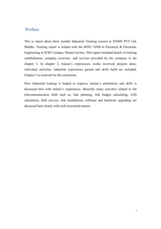
  • 19. 15 According to required height, a sufficient mobile tower must be there to place microwave antennas and sectors and RRUs. In rural areas where, no more links and technologies, guy towers are used because of easy placement and low cost. Guy towers are portable ones and can transport entire tower from one place to another place very easily. Most of the times, usual mobile towers are utilized. Usually, these towers consist with one or more ladders and platforms and have more safety options than guy towers. OUTDOOR UNITS Microwave antennas (Parabolic dish reflectors), Panel antennas (sector antennas), RRUs are usually called as outdoor units. REMOTE RADIO UNIT (RRU) The radio unit is a microwave radio with RF transceivers, which transmit and receive RF signals. Traffic signals from the indoor units are processed and converted to transmitter frequency and sent over the hop. The radio unit is fitted directly to the antenna as standard. It can also be installed separately and connected by a flexible waveguide to any antenna with standard waveguide interface (154 IEC-UBR). It can be disconnected and replaced without affecting the antenna alignment. There are connections for antenna alignment, radio cable and grounding. Two LEDs indicate alarm and power on/off. RRU is responsible for convert light into voltage signal to have better accuracy.
  • 20. 16 Figure 2. 4: A Remote Radio Unit (RRU) According to bandwidth, RRU is changed. At the beginning there were 2G RRUs which having mass of 37.5Kg. 3G RRU usually has mass of 23Kg approximately when 4G RRU is just 13Kg.
  • 21. 17 ANTENNA Figure 2. 5: 0.6m Microwave antenna
  • 22. 18 : Figure 2. 6: Microwave antenna with ODU Five different antenna types, fitting directly to the radio units, are available. 0.2m, 0.3m, 0.6m, 1.2m, and 1.8m are the available compact antennas. All antennas can also be installed separately and connected to the radio unit by a flexible waveguide. It is possible to choose between vertical and horizontal polarization. The antenna is fitted on an antenna support and does not have to be removed during maintenance after alignment. These antennas are work as both transmitter and receiver (Transceiver). These type antennas are called as “Parabolic dish reflectors” usually. Dish is covered with a leather to avoid from weather effects. Parabolic reflectors typically have a very high gain like 30-40 dB and low cross polarization. They also have a reasonable bandwidth, with the fractional bandwidth being at least 5 percent on commercially available models, and can be very wideband in the case of huge dishes from 0.3m to
  • 23. 19 4.6 meters commonly. Responsible from 150MHZ to 1.5GHZ frequency range. Frequency range is varying according to model and producer. As an example, smaller dish antennas typically operate somewhere between 2 and 28 GHz. The large dishes can operate in the VHF region (30-300 MHz), but typically need to be extremely large at this operating band. MAINTAINING EXISTING LINKS When the network grows up traffic demand get also increase. Also the new technologies come to the market and company uses those new technologies then existing links must update. The fault recovery of existing links has done by transmission section. First Sector antennas are placed on the tower. Then it’s connected to the RRU through coaxial cable called “jumper”. Whatever small voltage generated in the sector is comes to RRU and then converted it to a light signal. Fiber optic cables used to connect Base band Unit (BBU). Then that light signal is again converted to voltage signal. In data transmitting E1 standard cable is used in Sri Lanka according European Standard. E1 cables usually as eight pairs. E1 cables can connected to delivery ports called as Crones. By crones that signal may be linked with another link also. Suppose if Galle – Matara link can be connected with Colombo- Galle link using E1 cables at Galle. Then Matara can connect with Colombo Directly. Then as an outdoor unit, Antennas or dishes are placed. Towers are connected through these antennas. Every tower must be linked in a network to have island wide coverage. Parabolic dishes connect links through microwaves. Dish antennas is connected with ODU. ODU is connected with antenna. ODU converts data from the IDU into an RF signal for transmission. It also converts the RF signal from the far end to suitable data to transmit to the IDU. ODUs are weatherproofed units that are mounted on top of a tower either directly connected to a microwave antenna or connected to it through a
  • 24. 20 wave guide. Here ODUs are full duplex configured. The ODU receives its power from the IDU through a coaxial cable. ODU parameters are configured and monitored through the IDU. Each ODU is designed to operate over a predefined frequency band. For example 21.2 to 23.6GHz for a 23GHz system, 17.7 to 19.7GHz for a 18GHz system and 24.5 to 26.5GHz for a 26GHz system as for DMC XP4 ODUs. Suitable ground wire should be connected to the ODU ground lug to an appropriate ground point on the antenna mounting or tower for lightning protection. It should be noted that this unit is electronically controlled. Transmitted power is controlled by adjusting a value on the IDU which instructs the ODU to adjust the drive voltage on its Transmitter PIN diode attenuator. ODUs are categorized as 1+0, 1+1,2+0 and 2+2. 1+0 means ODU work only with active mode. At 1+1 ODU has standby option also. SECTOR ANTENNAS In its base stations Mobitel uses sector antennas (panels ) to provide radio coverage to the subscribers. These sector antennas normally transmit with a transmission power around -35 to - 40 db. This power level is adjusted by RBS. Sector antennas that we use in Mobitel support polarization diversity in order to increase its receiver sensitivity. In polarization diversity the receiver antenna has two antenna arrays one with -45º and other with +45º angles. Sometimes, frequency antennas are used. Dual frequency antennas are capable of operating in two separate frequency bands. These are used in sites where there is both GSM 900 and GSM 1800 radio base stations are present, so without having two separate antennas there can be used dual band or tri band antennas. In geometry, a "sector" is a "slice" or "wedge" of a circle. Picture a slice of a pie being lifted from the pie, and you get a visual image of a sector. A sector antenna is a directional antenna designed to cover this kind of geometric shape. There are different types of antenna in considering covering area. A 60 degree sector antenna covers 60 degrees of a 360 degree circle, while a 90 degree sector antenna covers a fourth of that same circle. The radiation areas don't end abruptly at 60, 90, or 120 degrees; these have a few degrees of overlap so you could,
  • 25. 21 for example, use three 120 degree sector antennas for full coverage of a circle. In real world, sector antennas have a range of about 4 to 5 km. Figure 2. 7: Antenna bracket with angle indicator.
  • 26. 22 Usually, in fitting antennas, the angle is considering much with getting connection with mobiles. Antenna bracket is used to keep antenna fix and set the required direction. Types of antennas Single Band Antenna Figure 2. 8: A single Band Antenna Single band antenna is also called as mono band antennas. By today these antennas are replaced rapidly because of invention of new technologies and bandwidths. Most of Mono band antennas are GSM900 ones.
  • 27. 23 Figure 2. 9: A dual band antenna
  • 28. 24 Dual band antennas consists two bandwidths or bands in one antenna. These are more popular because low space and low maintenance required. Bands are DCS1800, 3G or GSM900, DCS1800. INDOOR UNITS ACCESS MODULE MAGAZINE (AMM) The AMM houses the plug-in units and is designed for fitting in a 19" rack or cabinet. There are two types of AMM.  AMM 1U-1 is used for 1+0 terminals and can house one MMU and one TRU.  AMM 2U-4 is mainly used for 1+1 or two 1+0 terminals and can house up to four units; two MMUs and two TRUs. The plug-in units are inserted into the AMM from the front. The connection between plug in units is made through the backplane of the AMM. All indicators and external connector interfaces are located on the fronts of the plug-in units. Cables are routed to the left and right hand side of the front. The AMM has a front panel to protect the cables and connections. Indicators are visible through the front panel. Tools, used for removal of the plug-in units, are attached to the inside of the front panel PLUG-IN UNITS FOR THE AMM  Modem unit (MMU) The MMU is the indoor interface with the radio unit and contains a modulator and demodulator. The MMU provides traffics and capacity of 155Mbit/s and is frequency independent. One MMU per radio unit is required is required.  Traffic Unit (TRU) The main functions of the TRU is the generating and terminating g an SDH STM-1 or SONET OC-3 signal and transmit it to or receive it from the MMU. It also contains a
  • 29. 25 protection switching function used for protected terminal configuration. One TRU per terminal is required. Besides the main traffic (155Mbit/s), there are three auxiliary channels; one channel for wayside traffic and two service channels. The TRU comes in two versions; the TRU EL. With electrical traffic interface, and the TRU EL/OPT with both electrical and optical traffic interfaces FAN UNIT To guarantee sufficient cooling for the plug-in units, a fan unit is always fitted on top of the AMM. One fan unit per AMM is required. The cooling air enters at front of the AMM, flows between the units and out through openings at the back of the AMM. DC DISTRIBUTION UNIT (DDU) The optional Dc distribution unit is used for distribution of primary Dc power to a maximum of five MMUs or fan units. Each output is protected by an automatic type fuse (6A) combined with an on/off switch.
  • 30. 26 Figure 2. 10: A DUDU in BTS After ODU, data goes to IDU through IF cable (Intermediate frequency cable). IDU contains much of the intelligence of the system. Main functions of the IDU include Providing the Data interface, Error correction, Modulation and Demodulation, Alarm status monitoring and Site-to-site communications. An IDU located in an equipment shelter to interface with the operator interface and is connected to a close coupled ODU Antenna assembly on the tower by a single coaxial cable. The IDU is independent of any frequency band and will operate over all frequency ODUs. But it is capacity dependent and there are separate modules capable of handling different capacity inputs. Configuring and monitoring of link performance can be done through the IDU front panel. Display of Local & Remote radios and Alarm Relay DCDU BBU MUX
  • 31. 27 Status LEDs are there in the IDU front panel for fault identification. Memory backup inside the IDU ensures that it maintains its configuration in the event of a DC power loss. Radio Base Station In data transmission chapter, maintenance and repairing of radio base stations is also included. Radio base station (RBS) is the interface between mobile subscriber and the network. It provides radio coverage to the subscriber through the radio antenna. Operations department look after radio base station equipment as well as cooling (AC) units and power supplies used in the base stations. Mobitel Lanka uses types of RBS equipments they are namely,  RBS 2206  RBS 2207 Both of them are products of Erricsson. There is no significant difference between these two equipments except for the fact that RBS 2206 and all its related units operates in GSM 1800 frequency and RBS 2207 and all its related equipments operates in GSM 900 frequency band. There are some TDMA (Time division multiple access) radio base stations also used in Mobitel but there are only few sites operates in TDMA. TDMA is the technology which is used before GSM. Mobitel still has some customers who are using TDMA, but they are encouraged to migrate to GSM. There are more brands of BTS in the field as Alcatel- Lucent.
  • 32. 28 Figure 2. 11: Two Alcatel BTSs for GSM and DCS.
  • 33. 29 RTN600 series upgrading RTN stands for Regional Telecommunication Network. This instrument is made by Huawei. The OptiX RTN 600 series TDM/hybrid integrated radio transmission system (OptiX RTN 600 for short) is a digital microwave transmission system for data packets. The system provides end-to-end transmission from the access layer to the backbone layer and can work with optical network equipment for end-to-end service grooming and unified network management. With the evolution from TDM to IP, IP-based microwave transmission solutions have become a trend. The OptiX RTN 600 helps smooth evolution from TDM microwave transmission to IP-based microwave transmission, saving network construction and operation costs. The OptiX RTN 600 is available in two models, the OptiX RTN 620 and the OptiX RTN 605. RTN responsible in interconnecting links and create internetwork. The sharing capacity can be increased by changing modulation way and number of E1 cables connected with RTN. In doing that operation RTN is upgraded in both hardware and software sections. In working with Huawei RTN, there was as standard software named, U2000WebLct implemented by Huawei technologies. U2000WebLct installed PC or Laptop must be connected with RTN through Ethernet cable to connect with RTN. Internet explorer is associated with WebLct.
  • 34. 30 Figure 2. 12Screen shot of WebLct starting page
  • 35. 31 After log with the link, weblct shows link ID, link IP address, link name, extended ID with the far end tower also. Figure 2. 13NE attribute of a link It always shows far end tower and its details as follows. Figure 2. 14: Link power level, bandwidth, frequencies indicating in weblct
  • 36. 32 The air interface of the OptiX RTN 620 supports 7MHz to 56MHz channel bandwidth and QPSK to 256 QAM modulation mode. The TDM air interface is flexibly configurable from 4E1 to 75E1; while the throughput of native Ethernet service is flexibly configurable from 10 Mbit/s to 400 Mbit/s. With the design of single-device multiple RF directions and the networking microwave equipment, the OptiX RTN 620 delivers more flexible ring networking (PDH/SDH-Ring) and full timeslot cross- connection to any direction is available. Featuring quick service provision and adjustment, the OptiX RTN 620 decreases the number of DDF racks, external cable connectors, and IDU service interface units, while omitting the external ADM equipment. When the air interface link works properly (for example, in sunny days), a higher modulation mode is adopted to provide high-bandwidth transmission capabilities through the adaptive modulation (AM). This helps reduce the capital expenditure (CAPEX) by making full use of the bandwidth resources. When the quality of the air interface link degrades (for example, in heavy rain or heavy fog), a lower modulation mode is adopted to increase the anti-fading capabilities. This guarantees high-quality data transmission for key users. Making full use of frequency spectrum resources, the OptiX RTN 620 helps greatly reduce TCO. Combining cross polarization interference cancellation (XPIC) with the same channel dual polarization (CCDP) technology under the TDM mode, the OptiX RTN 620 doubles the transmission capacity under the same channel condition. The OptiX RTN 620 boasts sound protection mechanism, which includes 1+1 power protection; 1+1 and N+1 protection in TDM mode configuration; linear multiplex section protection between optical transmission link and STM-1 link; and two-fiber bi-directional multiplex section protection ring of the STM-4 optical link. In TDM mode, the OptiX RTN 620 supports SNCP for E1 services and ERPS protection, that is, hybrid ring for data services.
  • 37. 33 In upgrading RTN, first hardware upgrading must be done. Usually all the hardware equipment are shown in software. Figure 2. 15: Physical board architecture of RTN620 First two units (no.17 and no.15) are not in RTN. Those are in ODU. No.7 and no.5 units are responsible for IF cards. In this RTN there is one IFH1 card and one IFH2 card. Two cards for 1+1 operation as mentioned under ODU topic. No.5 unit is main IF card. No.7 is the standby IF card. In this operation, no.5 card has been replaced with IFH2 card. N0.8 slot responsible for the Ethernet card. Before upgrading there’s no EMS card in the RTN. EMS card is used to develop switching system from message switching to packet switching.
  • 38. 34 CHAPTER 3 Conclusion At ITSMS, could follow training period of three months and could gain both theoretical and practical knowledge also. Telecommunication is a vast area and day by day new technologies are introduces and job opportunities are generated. In training period, could involve with many projects of Dialog Telekom and Mobitel Lanka as installation, surveys, workshops, link configurations, testing (TSWR, LOS, etc.), Software upgrading (WebLCT 2000 of Huawei), Link planning. Telecommunication field training session is an adventure and practically builds one especially. Training establishment (ITSMS Pvt LTD was awarded as the best constructor in Asia region of Huawei in 2008, 2009 and 2010. Following training at that kind of place gained accuracy of tasks done, leadership, responsibility also. ITSMS is well standard mobile constructing company working according to related rules and regulations. They provide better services for trainees by providing monthly salary and overtime payments with leaves. They also Provides a good industrial training both theoretically and practically. To have to work with Qualified Engineers of world leading telecommunication companies and to have share ideas and get knowledge is a real benefit a trainee can get who, having industrial training at ITSMS. ITSMS also provides good transport facilities, accommodation facilities and all the basic needs such as office wears, food and beverages, training kits in their projects. If consider about my industrial training at ITSMS as an undergraduate trainee allowed me to collect uncountable number of experiences about telecommunication field, team leading, on time working, having responsibilities, industrial fault analysis and solving.
  • 39. 35 Trainings were not indoor always. Majority of practical sessions were done in outdoors at many places in Sri Lanka such as, Colombo regional area, Gampaha, Waththala, Biyagama, Seeduwa, Mabola, Anuradhapura, kekirawa, Puththalam, Mahawilachchiya, Jaffna, Vavuniya, Trinco, Polonnaruwa, Habarana, Kurunegala, Rathnapura, Galle, Kaluthara,Ampara, Batticaloe, Nelliadi, Nellikulam, Meerigama, chilaw, Mathale, Raththota, Dummalasuriya, etc. As training works Site drawing, site surveying, Link power strength calculation, IDU software upgrading, System error checking, Establishing multiflexers (MUX), Link establishment, 2G,3G and 4G cutovers, IDU data cards replacement or installing, Drive tests, preparing link documents and project documents can be included basically. Within Three months could have good priceless experiences about telecommunication field. Telecommunication field is not a comfortable field to have many facilities in the training period or at career level. It’s always associated with the real world and has to work outdoor with giant responsibilities. Each and every member of the team has big responsibility in working with a giant network such as keep the network active and eliminates losses. It’s a nice and adventurers experience to work at different locations at different times with different responsibilities. I would like be thankful to All ITSMS staff members especially, Engineering Division for their great help and guidance in making success may industrial training period and all other Engineers and technical officers in Mobitel Lanka, Dialog Telekom and Huawei Sri Lanka who associate with us and encouraged during my training period.
  • 40. 36 Abbreviations 2G: Second Generation. 3G: Third Generation. 4G: Fourth Generation. AM: Adaptive Modulation. AMM: Access Module Magazine. BBU: Base Band Unit. BTS: Base Transceiver Station. CAPEX: Capital Expenditure. DCDU: DC Distribution Unit. DCS: Digital Cellular System. DDF: Digital Distribution Frame EM: Electromagnetic. FU: frame Unit. GMSK: Gaussian method Minimum Shift Keying. GPS: Global Positioning System. GSM: Global System for Mobile Communication. IDU: Indoor Unit. IF: Intermediate Frequency. IP: Internet Protocol. ITSMS: Integrated Telecom System Management Services PVT. LTD. LOS: Line of Sight.
  • 41. 37 MMU: Modem Unit. MSC: Mobile Switching Center. MW: Micro Wave NTS: Network transmission System. ODF: Optical Distribution Unit. ODU: Outdoor Unit. PC: Personal Computer PDH: Pleschronous Digital Hierarchy. QAM: Quadrature Amplitude Modulation. QPSK: Quadrature Phase Shift Keying. RBS: Radio Base Station. RF: Radio Frequency. RND: Radio Network Design. RTN: Radio Transmission Network. Rx: Receiver. SDH: Synchronous Digital Hierarchy. TDMA: Time Division Multiple Access. VSWR: voltage standing wave Ratio.
  • 42. 38 References Electronic References  Official Web site of A&A Telecom Pvt. Ltd. A & A Telecommunication Engineering Services (Pvt) Ltd . 2013. A & A Telecommunication Engineering Services (Pvt) Ltd . [ONLINE] Available at:http://aatesl.com/Index.htm. [Accessed 21 March 2013]. Figure reference  (1) Weird & Wireless: RF "Line of Sight" (Electro-ramblings). 2013. Weird & Wireless: RF "Line of Sight" (Electro-ramblings). [ONLINE] Available at:http://www.electronicsweekly.com/blogs/electronics-weekly- blog/2009/10/weird-wireless-rf-line-of-sight.html. [Accessed 21 March 2013].
  • 43. 39