Technical Introduction to AriAnA Rescue Robot Team
•Télécharger en tant que PPTX, PDF•
3 j'aime•1,498 vues

This document which is presented by Amir H. Soltanzadeh outlines the technical issues applied in AriAnA rescue robot team.

Recommandé
Contenu connexe
Tendances
Tendances (20)
En vedette
En vedette (20)
Similaire à Technical Introduction to AriAnA Rescue Robot Team
Similaire à Technical Introduction to AriAnA Rescue Robot Team (20)
Dernier
Dernier (20)
Technical Introduction to AriAnA Rescue Robot Team
- 1. AriAnA Rescue Robot Team Technical Introduction Amir H. SoltanzadehRobotics Lab @ Engineering School IAUCTB
- 2. Outlines Introduction to USAR Robotics USAR as a real-world problem RoboCup Rescue Robot League Technical introduction Mechanical overview Hardware architecture Software architecture
- 4. What is USAR Robotics? Search To look through in a place or in an area carefully in order to find something missing or lost Rescue To free or deliver victim from confinement. USAR: Urban Search And Rescue
- 5. What is USAR Robotics? Search To look through in a place or in an area carefully in order to find something missing or lost Rescue To free or deliver victim from confinement. Developing robots to be used in USAR application
- 6. Why use robots for USAR? 3-D law Robots can help in Dirty,Dangerous, DullTasks. They can do what rescuers or rescue dogs can’t! voids smaller than person can enter voids on fire or oxygen depleted Lose ½ cognitive attention with each level of protection Void:1’x2.5’x60’ Void on fire
- 7. Why use robots for USAR? 3-D law Robots can help in Dirty, Dangerous, DullTasks. The most important person in a rescue attempt is the rescuer! Not enough trained people 1 survivor, entombed: 10 rescuers, 4 hours 1 survivor, trapped/crushed: 10 rescuers, 10 hours 135 rescuers died Mexico City, 65 in confined spaces
- 8. Why use robots for USAR? 3-D law Robots can help in Dirty,Dangerous, Dull Tasks. They save time! Time is very critical Golden 24 hours
- 9. Taxonomy of USAR Robots MAV USV Man-packable UAV Man-portable Big-size USAR robots UGV
- 10. Brief History of USAR Robotics Oklahoma City bombing (1995) The Idea of using robots in USAR domain (by R. Murphy andJ. Blitch) Hanshi-Awaji earthquake in Kobe City (1995) The trigger for theRoboCup Rescueinitiative WTC 9/11 (2001) First practical usage of robots in real USAR application After 2001 rescue robots were applied in several occasions: Boat robots (USV) were used after hurricanes Charley, Dennis, Katrina and Wilma Aerial robots (UAV) were used after earthquake in L’Aquila, Italy 0 6 15
- 11. RoboCup Rescue Robot League RoboCup Juniors Seniors Soccer Rescue @Home Soccer Rescue Simulation Simulation Dance Small Size Robot Middle Size Standard Platform Humanoid
- 12. RoboCup Rescue Robot League Tasks Finding victims in a simulated destructed building Identifying detected victims (signs of life and identity) Marking victims’ locations on an automatically generated map
- 13. RoboCup Rescue Robot League Test Arena Yellow Ramps Autonomous Robots Only Orange Steep Ramp Stairs Red Step-Field Radio Drop-Out Autonomous Mobility
- 14. AriAnA Rescue Robot Team
- 15. Brief History Start (2005) • Research phase in Shahed Research Center (2005) Becoming official team of IAUCTB (2006) • 7th place in final ranking of RoboCup Rescue (2006) Joining with AVA – Malaysia (2008) • 2nd place in ISME 2008 student projects (2008) • 7th place in RoboCup Rescue (2009) • 1st place in Khwarizmi Robotics Competitions (2010) 2009 2006 2007 2008 2009 2010 AVA - Malaysia (ISOP Int. Co.)
- 16. Mechanical Overview Mobile manipulation in rough terrain: Locomotion Manipulation
- 17. Locomotion Mobility as a problem: Rescue robots should be highly mobile. Compromising between Mobility and Complexity of locomotion systems is inevitable. Biomimicry has not yet been a suitable solution due to technical limitations: Nature does not create efficient locomotion systems (living beings must do numerous things). Intelligent control of advanced mobility robots is computationally power hungry. Mobility Complexity Efficiency Various Platforms (for variety of terrains) Complexity as less complicated as possible to fulfill a task
- 18. Hybrid Locomotion Our solution: Designing a walking mechanism which is not necessarily inspired from the nature. Legged systems are very hard to control! Decreasing complexity of control system by means of semi-active joint controlling Triangular Tracked Wheel Legged Wheeled Tracked Higher maneuverability on rough terrains Higher traction + Lower ground pressure Higher efficiency while steering
- 19. Concept of TTW Mechanism 2 DOF: Tracks (velocity & torque controlled) Triangular frames (semi-active joint): Active (position, velocity & torque controlled) Passive
- 20. Concept of TTW Mechanism Active joint controlling: Continuous movement: Tracks traveling -> suitable for flat grounds (This type is also available in passive mode) Discrete movement: Triangular frames rotation -> for rough terrains Combined movement: Both tracks and triangles -> for ultra-rough terrains
- 21. Concept of TTW Mechanism Passive joint controlling: Surface adaptation: Lateral adaptation: Increasing traction without control process Axial adaptation:Passing obstacles without control process Not actually controlled but is monitored!
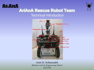
- 22. Manipulator Manipulator: Surveillance Camera Victim detection sensors Manipulation Camera Victim detection sensors Gripper Problems: DOF: Maneuverability Complexity Accuracy Payload End effector’s orientation correction mechanism: Combination of two parallelogram four-bar linkage with flexible links
- 23. Hardware Architecture Power Management System Main Board Communication System Motors & Drivers Video System Sensors
- 24. Power Management System Web based PMS: Power distribution Monitoring (voltage & current) Web Interfaced Intelligent control Self-health check
- 25. Main Board Industry grade Motherboard Small (115 x 165 mm) Powerful Pentium M 1.4 GHz, 2M L2 cache Robust Fanless (-40 to +80 C) Compact Flash compatible PC/104-plus compatible 0% ~ 90% relative humidity
- 26. Communications Internal Wired External Wireless Communication 5 GHz IEEE802.11a Access Point / Bridge
- 27. Motors & Drivers High efficiency brushless DC motors ~ 90% efficient 120 – 200W nominal power Highly efficient Gearhead ~ 80% efficient Incremental Encoder 1500 cpr Driver Torque control Velocity control Position control
- 28. Video System Camera Miniature cam (QTY = 3) Zoom cam (QTY = 1) Optical zoom Auto/Manual control Video Server Industry grade VS Higher quality Resolution: 720 x 480 Frame rate: up to 30 fps Robustness 3g shock & 1g vibration
- 29. Sensors Navigation Dead reckoning Odometry IMU Range sensors Scanning Laser Range Finder Vision Monocular Stereo Proximity sensors Ultrasonic GPS (Outdoor only)
- 30. Sensors Victim identification Temperature Thermal imaging camera Temperature scanner Vision Monocular Breathing CO2 sensor
- 31. Software Architecture Robotic Server HRI SLAM
- 32. Robotic Server Player (started in 2000) A universal driver for robotics Stage 2D multi-robot simulator Gazebo (started in 2003) High-fidelity 3D multi-robot simulator
- 33. Player / Stage / Gazebo Gazebo (3D simulation) Stage (2D simulation) Controller (client) Player (server) Controller (client) Controller (client) Player (server) Controller (client) TCP, UDP, Jini, Ice RS232, USB, 1394, TCP, Shared Mem © Brian Gerkey
- 34. Human Robot Interaction Easy to understand Graphical User Interface (GUI) Video-centric GUI Popular X-Box controller
- 35. SLAM SLAM: Simultaneous Localization And Mapping Generating a map of unknown environment while localizing the mapping system within that map
- 36. Navigation and SLAM SLAM Mapping Localization Integrated approaches Active localization Exploration Motion control © Makarenko et al
- 37. The SLAM Problem Global map (what robot thinks) Ground truth map (what happens) Local map (what robot sees) Given Robot controls Nearby measurements Estimate Robot state (position, orientation) Map of world features
- 38. Structure of SLAM Problem mj Zk,j mi Zk-1,i Xk-1 Xk uk
- 39. Why SLAM is hard? Chicken and egg problem: robot path and map are both unknown In the real world, the mapping between observations and landmarks is unknown Picking wrong data associations can have catastrophic consequences Pose error correlates data associations Robot pose uncertainty