SlideShare une entreprise Scribd logo
1  sur  56
Télécharger pour lire hors ligne
Broadband System - N
                           Satellites are spaced every
                            2nd degrees above earth


"C" Band
Toward satellite 6.0 GHz                                 "L" Band
Toward earth 4.0 GHz                                     Toward satellite 14.0 GHz
                                                         Toward earth 12.0 GHz


                TV
            TRANSMITTER
                           Headend

                                       Cable area

                                                                                     1
        Test Equipments Required for a HFC System.
RF test equipment can be divided in two sections.

•   Single equipment capable of reading the strength of a
    Television Channels.
•   Multi function meter, capable of reading;
    •   TV channel signal strength
    •   Digital signal (Power meter)
    •   Multi channel reading (Slope or Tilt)
    •   Spectral view of all the channels carried by an HFC system
    •   C/N measurement.
    •   Distortion measuring (C-N, CTB and CSO)
    •   Frequency Response (Peak & Valley response)
    •   QAM reading (BER, MER and FEC)
    •   Return alignment tool. (Response and Ingress)
    •   Ingress reading (Leakage)
                                                                     2
Filed Strength Meter capable of reading Television Channels.


      This equipment read the level of a single TV channel or a single
      FM music channel. These level can be read as TV channel or
      Frequency. They also give you the difference in level between
      the Video and Audio of TV channel. They can usually read signal
      from: 5 to 870 MHz.


                                                                         3
Field Strength Meter

         Video
                 300 to 400 KHz                              Most FSM read between
                                                             300 to 400 KHz of band
                      6.0 MHz       Audio                             width.
    0
                                            300 to 400 KHz

   -10

                                                   How it is display on the
   -20                                              Field Strength Meter

   -30


dB -40


   -50


   -60


   -70
                    3.59 MHz
                          4.5 MHz
                                                                                      4
Multi Function FSM


Multi function meter can be classified in two types;
•Meter for customer installation
•Meter for complete system verification.


Installation FSM                       Multifunction HFC Analyzer


                                                                    5
Multi Function FSM


   Installation FSM


                      6
Installation FSM


The Model One from Trilithic is an installation meter that can
            perform the following functions.


Single channel         Single channel          Digital signal
   reading             Spectral View             Strength


                                                                 7
Installation FSM


The Model One from Trilithic is an installation meter that can
            perform the following functions.


                    Favourites channels           AC – DC
 Tilt View                 View                   Reading


                                                                 8
Installation FSM


Below are examples of a signal been read by the Model One F.S.M.

           Analog TV channel                 QAM TV channel


                                                                   9
Multifunction HFC Analyzer


         860 DSPi


                             10
Meter for complete system verification.


                          BLOCK DIAGRAM

RF
INPUT
                RF FRONT END                          DISPLAY

                    MULTI-BW I.F.


                           HIGH-SPEED              DISPLAY DRIVER
                           12-BIT DIGITIZER


        DIRECT DIGITAL          “POWER - PC” and
        SYNTHESIZER              DSP PROCESSORS        KEYPAD


                                                   ETHERNET / RS-232C
                                                   COMMUNICATIONS


                                                                        11
Meter for complete system verification.

                         Standard functions.

Single Channel Measurement

- NTSC or PAL video, audio, SAP.
- Audio demodulation.
- Hum (50/60Hz, 100/120Hz, 1KHz L.P.)
- C/N on active channel channels.
- CTB, CSO.
- Depth of Modulation.
- QAM Haystack with power.
- Toggle to 1-chan. spectrum mode.


                                                  12
Meter for complete system verification.


-
    Full Plan Measurement.
    - Level, CTB, CSO, Hum and C/N on
      designated channels - all if possible

-
    Tilt / 8 Channel Plan
    - Auto Gain and Tilt calculation

-   FCC Test

    - Drop, Block and Tap

          -

          -

          -


                                                    13
Meter for complete system verification.


- QAM, QPSK
- Constellation, MER,
  pre and post BER, C/(N+I)?
- Spectrum under active signal


                                              14
Meter for complete system verification.


  QAM-DOCSIS channel, measuring; Level, MER and BER.


64 QAM DOCSIS signal.           256 QAM DOCSIS signal.


                                                         15
Meter for complete system verification.


· RSVP
   Up to 8 frequencies

· SSR
   New combined displays

· Ingress comparison:
   SST vs. current location


                                            16
Meter for complete system verification.


Spectrum Analyzer Option:
· Span 0, 100 KHz to 860 MHz
· Resolution Bandwidth 10 KHz
  to 3 MHz in 1,3 format
· Video Bandwidth 100 Hz to
  3 MHz in 1,3 format

· Spur free Display Range 60 dB

· Noise floor -50 dBmV in 10 KHz
   resolution
· Display smoothed to approximate
  an analog analyzer


                                              17
Meter for complete system verification.


                                          4   8 d B m V
                                          4   7
                                          4   6
                                          4   5
                                          4   4
                                          4   3
                                          4   2
                                          4   1
                                          4   0
                                          3   9
                                          3   8
                                          3   7


5-40 MHz


                                                          18
Meter for complete system verification.

           Spectrum Analyzer Measurement.


                                            4   8 d B m V
                                            4   7
                                            4   6
                                            4   5
                                            4   4
                                            4   3
                                            4   2
                                            4   1
                                            4   0
                                            3   9
                                            3   8
                                            3   7


5-40 MHz


                                                            19
Meter for complete system verification.


                                          4   8 d B m V
                                          4   7
                                          4   6
                                          4   5
                                          4   4
                                          4   3
                                          4   2
                                          4   1
                                          4   0
                                          3   9
                                          3   8
                                          3   7


5-40 MHz


                                                          20
Fiber Optic Test
  Equipments


                   21
HFC System


Since a HFC system requires two types of communications, one type
been fiber optic and the other one been coaxial cable, two type of test
equipments are require to test both sections of a system.
            •Test equipment for coaxial cable distribution.


            •Test equipment for fiber optic communication.


                                                                   22
Test equipments for fiber optic communication


Test equipments required for the fiber optic section are the following;
•Power meter.
•Light Source.
•OTDR (Optical Time Domain Reflectometer).
•OSA (Optical Spectrum Analyser).
•Talk Set.
•Visual Fault Locator
•Optical Fiber Identifier.
•Optical Scope.
•PMD Analyzer.


                                                                     23
Power meter.


  Power meter are required to measure the power output of the
optic transmitting equipment, the input of the receiving equipment
              and the actual loss of a fiber optic link.


      GN-6025
      Freq.: 800 to 1700 nm.
      +5 to – 70 dBm
      GN-6025C *
      Freq.: 800 to 1700 nm.
      +20 to – 60 dBm
      * Best for HFC system.


                                                              24
Light Source.


Optical Light Source gives a calibrated light output that can be used
  for testing a fiber link, when no other light signal are available.


        GN-6250 *
        1310-1550 nm.
        - 8.0 dBm
        GN-6260
        1550-1625 nm
        - 8.0 / - 5.0 dBm
        *Best for HFC system.


                                                                 25
OTDR (Optical Time Domain Reflectometer)


OTDR are used to check continuity and signal loss on fiber optic link.


  CMA-4000-MDK-1
  •8.4” Colour Matrix Display.
  •30/28 dB 1310/1550 nm.
  •Dual Single Opt. Module.
  •Hard Transit Case.
  •Network VisionNet Plus Software.


                                                                 26
OTDR (Optical Time Domain Reflectometer)


OTDR are used to check continuity and signal loss on fiber optic link.


  CMA-4000-DK-2-X
  •8.4” Colour Matrix Display.
  •36/34 dB 1310/1550 nm.
  •Built-in-Hard drive.
  •Built in Light Source.
  •Dual Single Opt. Module.
  •Hard Transit Case.
  •Network VisionNet Plus Software.


                                                                 27
OTDR (Optical Time Domain Reflectometer)


OTDR are used to check continuity and signal loss on fiber optic link.


  CMA-4000-DK-3-X
  •8.4” Colour Matrix Display.
  •40 dB 1310/1550 nm.
  •Built-in-Hard drive.
  •Dual Single Opt. Module.
  •Built in Light Source.
  •Hard Transit Case.
  •Network VisionNet Plus Software.


                                                                 28
OTDR (Optical Time Domain Reflectometer)


Printed view of two fiber optic links measurements.


                                                  29
The Growing Demand for Data Transport


It is clear, as we approach the 21th century the remarkable evolution
     in information services in our society. This revolution in
     information has been promoted by;
    •   Higher number of long distance phone call
    •   Internet traffic
    •   Multimedia services
    •   Transport of medical picture at high speed
    •   Financial exchanges (Credit card, Direct payments etc.)
    •   Demand for more television signal

These are the reason, why information services need increase in capacity


                                                                      30
Capacity of a fiber optic network


Since to-day, the capacity of a fiber optic network is limited
to 10 Gbps, soon to be 40 Gbps, we must find other way to
increase the fiber optic’s capacity

Let have a look at the possibility of augmenting the capacity
of the network.


                                                             31
Ways of Increasing the Capacity of a Fiber Optic System.


   * By installing more fiber.
   * By augmenting the fiber optic capacity.
   * By using the technology of CWDM or DWDM.


                                                    32
Installing New Fiber Optic


Installing new fiber optic can be very expensive and
difficult in areas like;

•Big city.
•Submarine cable.
•Underground duck been completely full.
•Lack of space in CO (Central Office)


                                                  33
SONET transmission capacity


Optic           Mb/s        Tel. Conv.   TV ch.
DS0             0.064        1           *
T1              1.54         24          *
DS3             44.74        672         *
OC-3            155.52       2,016       2
OC-12           622.08       8,064       12
OC-48           2,488.32     32,256      48
OC-96           4,976.64     77,760      55
OC-192          9,953.28     155,520     111
* Only slow scan picture.


                                                  34
The DWDM Technology


The DWDM technology, consist on transmitting many
optical waves on the same fiber optic.
       Dense Wave Division Multiplexing

   


                                      


                                                    35
Thirty Two Wavelengths DWDM Frequencies.


                                           36
OSA (Optical Spectrum Analyser).


                                   37
OSA (Optical Spectrum Analyser).


OSA are used to measure Carrier to Noise, Signal amplitude, EDFA’s
     flatness and bandwidth response and signal frequency.


Model CMA4791
Wavelength:      1520 - 1570 nm
Power Range:     +20 to –60 dBm
Power Range:     +10 to –70 dBm opt.
Channel table:   256 channels.


                                                             38
Talk Set.


Talk set are used to communicates between the field
technician and the central office people over fiber optic.

Optical Specifications
For Full-duplex

OVS-6000
1310 nm
Range: >30 dB

OVS-6100
1310 nm
Range: >50 dB

Above on single-mode fiber.
         single-


                                                        39
Visual Fault Locator


The VFL-670 works at 670 nm with              an output of –4.0 dBm. It is
capable of a distance of 2 kilometres. It give a RED visible light, where
there is a break or a bad connected installed. The unit work for multimode
and single mode fiber optic.
                                                                     40
Optical Fiber Connector Inspection.


The FS-X00 Fiberscope is ideal for inspecting optic connector. This unit
will give a 200X or 400X view for multimode and single mode fiber
connector. You need one of the following ADAPTER: FC-APC, ST, SC-APC,
or D4.

                                                                   41
Problems with Fiber Optic Transport System.


                                         42
Two majors problems with Fiber optic transport System


      • Chromatic Dispersion.

      • Polarization Mode Dispersion.


                                                  43
What is Dispersion.


The spreading or broadening of light pulses as they
           propagate through the fiber


                                                  44
Digital Communication Bit Times

                                                                Dispersion

SONET     SDH          Transmission Rate        Bit Time           Limit

OC-1
OC-                    51.84 Mb                  19.29     ns      2 ns

OC-3
OC-      STM-1
         STM-         155.52 Mb                   6.43     ns   640 ps

OC-12
OC-      STM-4
         STM-         622.08 Mb                   1.61     ns   160 ps

OC-24
OC-                  1244.16 Mb      (1.2 Gb)   803.76     ps     80 ps

OC-48
OC-      STM-16
         STM-        2488.32 Mb      (2.4 Gb)   401.88     ps     40 ps

OC-192
OC-      STM-64
         STM-        9953.28 Mb      (10 Gb)    100.47     ps     10 ps

OC-768
OC-      STM-256
         STM-      39,813.12 Mb      (40 Gb)     25.12     ps      2 ps


                    Above are SONET
                    •Transmission Rate
                    •Bit Time
                    •Dispersion Limit                                        45
Eye Diagrams - What They Are


• For each bit time, there are 8 possibles conditions:

                      1 bit time

 0 0 0                                      1 0 0


 0 0 1                                      1 0 1


 0 1 0                                      1 1 0


 0 1 1                                      1 1 1


• Combine (overlap) them for an eye diagram


                                                         46
Typical Good and Bad Eye Diagram (High Bit Error Rate)


One
Level

                             Sample
                             Window

Zero
Level
                             1 bit time

 One
Level

                             Sample
                             Window

Zero
Level

                             1 bit time
                                                         47
What is Polarization Mode Dispersion
       What is Polarization Mode Dispersion

Polarization Mode Dispersion is basically due to the fact that
  different polarizations of light travel at different speeds.


  Off Center             Different Size         Non-Circular


        Above are some the majors causes of PMD.


                                                               48
Differential Delay


                                    The difference in speed between
                                    the two cars (or two wavelengths
                                    of light) causes them to arrive at
                                    the end at different times. The
                                    longer the distance, the more
              65 mph                time difference between them.
              55 mph
                                  65 mph
   Start
0 sec. diff                       55 mph
                                                                           65 mph
                  After 1 mille
                  10 sec. diff                                         55 mph

                                                      After 20 mille
                                                      200 sec. diff


                                                                                49
Reading of Chromatic Dispersion.


Above are reading of Chromatic Dispersion between 1260 to 1560
                         nanometre.
                                                           50
Chromatic Dispersion.


                                +20 -                                                            -
        Dispersion (psnmxkm)
                                                     Standard Single-Mode Fiber
                                +10 -                                                            -


                                 0   -                                                           -

                                                                                  DWDM
                                                                                   band
                                -10 -                                                            -

                                                             D-NZ-DSF
                                -20 -                                                            -


                                         1300         1400              1500              1600
                                                         Wavelength (nm)

As there are two types of fiber optic with different type of Chromatic
Dispersion. Above is the Chromatic Dispersion for standard fiber and NZ-
DSF (None Zero Chromatic Dispersion). This type aof fiber optic is used
for long distance transport and utilized the 1550 nm light frequency.
                                                                                                     51
The Results of PMD.


Delay caused by
     PMD.


                               52
PMD Analyzer


The PMD440 is capable of measuring PMD (Polarisation Mode
Dispersion). PMD can occur at 1310 and 1550 nm. PMD will be one of
the major problem with fiber optic for long distance and high speed
data transmission.
                                                                53
Reading PMD Results.


Good PMD Measurement           Bad PMD Measurement


                                                     54
PMD and HFC System.


A HFC system requires the following PMD requirements:
For 1310 nm is:      0.5 ps sk-km.
For 1550 nm is:      0.2 ps sk-km.
Any worse PMD readings than the above, would cause a
bad CSO (Composite Second Order) reading at the NODE.


                                                        55
56

Contenu connexe

Tendances

Rf receiver design case studies
Rf receiver design case studiesRf receiver design case studies
Rf receiver design case studiesPhani Kumar
 
Possibilities and limitations of Extended Spectrum DOCSIS return path
Possibilities and limitations of Extended Spectrum DOCSIS return pathPossibilities and limitations of Extended Spectrum DOCSIS return path
Possibilities and limitations of Extended Spectrum DOCSIS return pathTeleste Corporation
 
Es'hail2 1er satellite radioamateur géostationnaire QATAR OSCAR-100
Es'hail2 1er satellite radioamateur géostationnaire QATAR OSCAR-100Es'hail2 1er satellite radioamateur géostationnaire QATAR OSCAR-100
Es'hail2 1er satellite radioamateur géostationnaire QATAR OSCAR-100Passion Radio Amateur
 
Introduction to RF & Wireless - Part 4
Introduction to RF & Wireless - Part 4Introduction to RF & Wireless - Part 4
Introduction to RF & Wireless - Part 4Carl Weisman
 
Introduction to RF & Wireless - Part 3
Introduction to RF & Wireless - Part 3Introduction to RF & Wireless - Part 3
Introduction to RF & Wireless - Part 3Carl Weisman
 
Extended Upstream - The heat is on!
Extended Upstream - The heat is on!Extended Upstream - The heat is on!
Extended Upstream - The heat is on!Teleste Corporation
 
A pragmatic approach to Extended Spectrum DOCSIS: November 2020
A pragmatic approach to Extended Spectrum DOCSIS: November 2020A pragmatic approach to Extended Spectrum DOCSIS: November 2020
A pragmatic approach to Extended Spectrum DOCSIS: November 2020Teleste Corporation
 
10.7mW, 2.1 sq mm, 0.13um CMOS GPS radio
10.7mW, 2.1 sq mm, 0.13um CMOS GPS radio10.7mW, 2.1 sq mm, 0.13um CMOS GPS radio
10.7mW, 2.1 sq mm, 0.13um CMOS GPS radioDavid Tester
 
Analysis of GSM ORFS Issue
Analysis of GSM ORFS IssueAnalysis of GSM ORFS Issue
Analysis of GSM ORFS Issuecriterion123
 
Shenzhen Hifibercom Technology Co.,Ltd hot sales 1.25G CSFP BIDI 20KM
Shenzhen Hifibercom Technology Co.,Ltd  hot sales 1.25G CSFP BIDI 20KMShenzhen Hifibercom Technology Co.,Ltd  hot sales 1.25G CSFP BIDI 20KM
Shenzhen Hifibercom Technology Co.,Ltd hot sales 1.25G CSFP BIDI 20KMAngelaLuo10
 
Rdb45350 access point_specifications
Rdb45350 access point_specificationsRdb45350 access point_specifications
Rdb45350 access point_specificationsAdvantec Distribution
 

Tendances (20)

Mfc
MfcMfc
Mfc
 
Rf receiver design case studies
Rf receiver design case studiesRf receiver design case studies
Rf receiver design case studies
 
Feature dvbs3
Feature dvbs3Feature dvbs3
Feature dvbs3
 
Spaun
SpaunSpaun
Spaun
 
Possibilities and limitations of Extended Spectrum DOCSIS return path
Possibilities and limitations of Extended Spectrum DOCSIS return pathPossibilities and limitations of Extended Spectrum DOCSIS return path
Possibilities and limitations of Extended Spectrum DOCSIS return path
 
Es'hail2 1er satellite radioamateur géostationnaire QATAR OSCAR-100
Es'hail2 1er satellite radioamateur géostationnaire QATAR OSCAR-100Es'hail2 1er satellite radioamateur géostationnaire QATAR OSCAR-100
Es'hail2 1er satellite radioamateur géostationnaire QATAR OSCAR-100
 
General/Digital up conversion
General/Digital up conversionGeneral/Digital up conversion
General/Digital up conversion
 
Introduction to RF & Wireless - Part 4
Introduction to RF & Wireless - Part 4Introduction to RF & Wireless - Part 4
Introduction to RF & Wireless - Part 4
 
Introduction to RF & Wireless - Part 3
Introduction to RF & Wireless - Part 3Introduction to RF & Wireless - Part 3
Introduction to RF & Wireless - Part 3
 
Extended Upstream - The heat is on!
Extended Upstream - The heat is on!Extended Upstream - The heat is on!
Extended Upstream - The heat is on!
 
GFSK DEMODULATOR
GFSK DEMODULATORGFSK DEMODULATOR
GFSK DEMODULATOR
 
A pragmatic approach to Extended Spectrum DOCSIS: November 2020
A pragmatic approach to Extended Spectrum DOCSIS: November 2020A pragmatic approach to Extended Spectrum DOCSIS: November 2020
A pragmatic approach to Extended Spectrum DOCSIS: November 2020
 
CATV Headend (Basic)
CATV Headend (Basic)CATV Headend (Basic)
CATV Headend (Basic)
 
10.7mW, 2.1 sq mm, 0.13um CMOS GPS radio
10.7mW, 2.1 sq mm, 0.13um CMOS GPS radio10.7mW, 2.1 sq mm, 0.13um CMOS GPS radio
10.7mW, 2.1 sq mm, 0.13um CMOS GPS radio
 
Mfc
MfcMfc
Mfc
 
Analysis of GSM ORFS Issue
Analysis of GSM ORFS IssueAnalysis of GSM ORFS Issue
Analysis of GSM ORFS Issue
 
LTE Measurement: How to test a device
LTE Measurement: How to test a deviceLTE Measurement: How to test a device
LTE Measurement: How to test a device
 
Shenzhen Hifibercom Technology Co.,Ltd hot sales 1.25G CSFP BIDI 20KM
Shenzhen Hifibercom Technology Co.,Ltd  hot sales 1.25G CSFP BIDI 20KMShenzhen Hifibercom Technology Co.,Ltd  hot sales 1.25G CSFP BIDI 20KM
Shenzhen Hifibercom Technology Co.,Ltd hot sales 1.25G CSFP BIDI 20KM
 
Work microwave
Work microwaveWork microwave
Work microwave
 
Rdb45350 access point_specifications
Rdb45350 access point_specificationsRdb45350 access point_specifications
Rdb45350 access point_specifications
 

En vedette

Arrayed fiberoptics ANC presentation
Arrayed fiberoptics ANC presentationArrayed fiberoptics ANC presentation
Arrayed fiberoptics ANC presentationBen Connors
 
Building Next Generation Transport Networks
Building Next Generation Transport NetworksBuilding Next Generation Transport Networks
Building Next Generation Transport NetworksInfinera
 
OTDR OPERATION BASICS
OTDR OPERATION BASICSOTDR OPERATION BASICS
OTDR OPERATION BASICSimtfiber
 
Inria - Extrait du catalogue logiciels calcul haute performance (HPC)
Inria - Extrait du catalogue logiciels calcul haute performance (HPC)Inria - Extrait du catalogue logiciels calcul haute performance (HPC)
Inria - Extrait du catalogue logiciels calcul haute performance (HPC)Inria
 
Inria - Activity report 2010
Inria -  Activity report 2010Inria -  Activity report 2010
Inria - Activity report 2010Inria
 
Premium Inspection Report
Premium Inspection ReportPremium Inspection Report
Premium Inspection ReportTom Rosenberger
 
Pimp The Room I by Ekevdb
Pimp The Room I by EkevdbPimp The Room I by Ekevdb
Pimp The Room I by Ekevdbguestbbb1a9
 
Full Prism Solution Overview
Full Prism Solution OverviewFull Prism Solution Overview
Full Prism Solution OverviewAndrew Bain
 
Os primeiros poboadores: cultura, sociedade e lingua
Os primeiros poboadores: cultura, sociedade e linguaOs primeiros poboadores: cultura, sociedade e lingua
Os primeiros poboadores: cultura, sociedade e linguanoagaliza
 
Chapter 2 goal setting strategies
Chapter 2 goal setting strategiesChapter 2 goal setting strategies
Chapter 2 goal setting strategiessritter1
 
Festas do San Xoán
Festas do San XoánFestas do San Xoán
Festas do San Xoánnoagaliza
 
Градиент Опека
Градиент ОпекаГрадиент Опека
Градиент ОпекаPaul Serikov
 

En vedette (20)

Hfc c he example of hfc
Hfc c he example of hfcHfc c he example of hfc
Hfc c he example of hfc
 
Hfc l alignment and system maintenance
Hfc l alignment and system maintenanceHfc l alignment and system maintenance
Hfc l alignment and system maintenance
 
Arrayed fiberoptics ANC presentation
Arrayed fiberoptics ANC presentationArrayed fiberoptics ANC presentation
Arrayed fiberoptics ANC presentation
 
Attenuation in fiber
Attenuation in fiberAttenuation in fiber
Attenuation in fiber
 
Building Next Generation Transport Networks
Building Next Generation Transport NetworksBuilding Next Generation Transport Networks
Building Next Generation Transport Networks
 
OTDR OPERATION BASICS
OTDR OPERATION BASICSOTDR OPERATION BASICS
OTDR OPERATION BASICS
 
Inria - Extrait du catalogue logiciels calcul haute performance (HPC)
Inria - Extrait du catalogue logiciels calcul haute performance (HPC)Inria - Extrait du catalogue logiciels calcul haute performance (HPC)
Inria - Extrait du catalogue logiciels calcul haute performance (HPC)
 
Inria - Activity report 2010
Inria -  Activity report 2010Inria -  Activity report 2010
Inria - Activity report 2010
 
Premium Inspection Report
Premium Inspection ReportPremium Inspection Report
Premium Inspection Report
 
Pimp The Room I by Ekevdb
Pimp The Room I by EkevdbPimp The Room I by Ekevdb
Pimp The Room I by Ekevdb
 
Bct Terms 1 3
Bct Terms 1 3Bct Terms 1 3
Bct Terms 1 3
 
Hfc g rf amplifiers
Hfc g rf amplifiersHfc g rf amplifiers
Hfc g rf amplifiers
 
手抜力
手抜力手抜力
手抜力
 
Full Prism Solution Overview
Full Prism Solution OverviewFull Prism Solution Overview
Full Prism Solution Overview
 
Os primeiros poboadores: cultura, sociedade e lingua
Os primeiros poboadores: cultura, sociedade e linguaOs primeiros poboadores: cultura, sociedade e lingua
Os primeiros poboadores: cultura, sociedade e lingua
 
Land Inspection Report
Land Inspection Report Land Inspection Report
Land Inspection Report
 
Chapter 2 goal setting strategies
Chapter 2 goal setting strategiesChapter 2 goal setting strategies
Chapter 2 goal setting strategies
 
Test 2
Test 2Test 2
Test 2
 
Festas do San Xoán
Festas do San XoánFestas do San Xoán
Festas do San Xoán
 
Градиент Опека
Градиент ОпекаГрадиент Опека
Градиент Опека
 

Similaire à Hfc n test equip for hfc

Tektronix and keithley product and apps update q3 2016
Tektronix and keithley product and apps update q3 2016Tektronix and keithley product and apps update q3 2016
Tektronix and keithley product and apps update q3 2016Jeff Sable
 
spectrum analyzers ppt
spectrum analyzers pptspectrum analyzers ppt
spectrum analyzers pptAvinash Jadhav
 
ZVxPlus Product Note: Nonlinear Extension Kit for R&S VNA
ZVxPlus Product Note: Nonlinear Extension Kit for R&S VNAZVxPlus Product Note: Nonlinear Extension Kit for R&S VNA
ZVxPlus Product Note: Nonlinear Extension Kit for R&S VNANMDG NV
 
MSK 200 Digital Transport Stream Analyzer
MSK 200 Digital Transport Stream AnalyzerMSK 200 Digital Transport Stream Analyzer
MSK 200 Digital Transport Stream Analyzeremzach1831
 
Oscilloscope Fundamentals, Hands-On Course at EELive 2014
Oscilloscope Fundamentals, Hands-On Course at EELive 2014Oscilloscope Fundamentals, Hands-On Course at EELive 2014
Oscilloscope Fundamentals, Hands-On Course at EELive 2014Rohde & Schwarz North America
 
Emelec partial discharge measurement services
Emelec partial discharge measurement servicesEmelec partial discharge measurement services
Emelec partial discharge measurement servicesAbdollatif Bashghareh
 
Color flow medical cardiac ultrasound
Color flow medical cardiac ultrasoundColor flow medical cardiac ultrasound
Color flow medical cardiac ultrasoundLarry Miller PhD
 
Range to Fault for PIM Testing (Kaelus white paper)
Range to Fault for PIM Testing (Kaelus white paper)Range to Fault for PIM Testing (Kaelus white paper)
Range to Fault for PIM Testing (Kaelus white paper)Kaelus
 
IEEE 802.22 WRAN Standard
IEEE 802.22 WRAN StandardIEEE 802.22 WRAN Standard
IEEE 802.22 WRAN Standardsonix022
 
RIGOL Real-time spectrum analyzer RSA5000 Series
RIGOL Real-time spectrum analyzer RSA5000 SeriesRIGOL Real-time spectrum analyzer RSA5000 Series
RIGOL Real-time spectrum analyzer RSA5000 SeriesNIHON DENKEI SINGAPORE
 
RFS Advanced Passive Components for UHF Broadcast Spectrum Reallocation
RFS Advanced Passive Components for UHF Broadcast Spectrum ReallocationRFS Advanced Passive Components for UHF Broadcast Spectrum Reallocation
RFS Advanced Passive Components for UHF Broadcast Spectrum ReallocationCReynhoutSVM
 
Advanced Passive Components for UHF Broadcast Spectrum Reallocation
Advanced Passive Components for UHF Broadcast Spectrum ReallocationAdvanced Passive Components for UHF Broadcast Spectrum Reallocation
Advanced Passive Components for UHF Broadcast Spectrum ReallocationRadioFrequencySystems
 
Audio Video Engineering
Audio Video Engineering Audio Video Engineering
Audio Video Engineering Yogesh kanade
 
Interviewquestionofgsm 141012233825-conversion-gate01
Interviewquestionofgsm 141012233825-conversion-gate01Interviewquestionofgsm 141012233825-conversion-gate01
Interviewquestionofgsm 141012233825-conversion-gate01Jitendra kumar Singh
 
SYM Technology RF Spectrum Performance Analysis
SYM Technology RF Spectrum Performance AnalysisSYM Technology RF Spectrum Performance Analysis
SYM Technology RF Spectrum Performance AnalysisTodd Masters
 
Huaptec tarec in partner web-site
Huaptec tarec in partner web-siteHuaptec tarec in partner web-site
Huaptec tarec in partner web-sitefrankjoh
 
Cambium networks pmp_430_access_point_(5.8_g_hz)_specification
Cambium networks pmp_430_access_point_(5.8_g_hz)_specificationCambium networks pmp_430_access_point_(5.8_g_hz)_specification
Cambium networks pmp_430_access_point_(5.8_g_hz)_specificationAdvantec Distribution
 
473 tactical cellular jamming system
473 tactical cellular jamming system473 tactical cellular jamming system
473 tactical cellular jamming systemriskis
 

Similaire à Hfc n test equip for hfc (20)

Tektronix and keithley product and apps update q3 2016
Tektronix and keithley product and apps update q3 2016Tektronix and keithley product and apps update q3 2016
Tektronix and keithley product and apps update q3 2016
 
spectrum analyzers ppt
spectrum analyzers pptspectrum analyzers ppt
spectrum analyzers ppt
 
ZVxPlus Product Note: Nonlinear Extension Kit for R&S VNA
ZVxPlus Product Note: Nonlinear Extension Kit for R&S VNAZVxPlus Product Note: Nonlinear Extension Kit for R&S VNA
ZVxPlus Product Note: Nonlinear Extension Kit for R&S VNA
 
MSK 200 Digital Transport Stream Analyzer
MSK 200 Digital Transport Stream AnalyzerMSK 200 Digital Transport Stream Analyzer
MSK 200 Digital Transport Stream Analyzer
 
Ds2460q datasheet
Ds2460q datasheetDs2460q datasheet
Ds2460q datasheet
 
Oscilloscope Fundamentals, Hands-On Course at EELive 2014
Oscilloscope Fundamentals, Hands-On Course at EELive 2014Oscilloscope Fundamentals, Hands-On Course at EELive 2014
Oscilloscope Fundamentals, Hands-On Course at EELive 2014
 
Emelec partial discharge measurement services
Emelec partial discharge measurement servicesEmelec partial discharge measurement services
Emelec partial discharge measurement services
 
Color flow medical cardiac ultrasound
Color flow medical cardiac ultrasoundColor flow medical cardiac ultrasound
Color flow medical cardiac ultrasound
 
Range to Fault for PIM Testing (Kaelus white paper)
Range to Fault for PIM Testing (Kaelus white paper)Range to Fault for PIM Testing (Kaelus white paper)
Range to Fault for PIM Testing (Kaelus white paper)
 
IEEE 802.22 WRAN Standard
IEEE 802.22 WRAN StandardIEEE 802.22 WRAN Standard
IEEE 802.22 WRAN Standard
 
RIGOL Real-time spectrum analyzer RSA5000 Series
RIGOL Real-time spectrum analyzer RSA5000 SeriesRIGOL Real-time spectrum analyzer RSA5000 Series
RIGOL Real-time spectrum analyzer RSA5000 Series
 
RFS Advanced Passive Components for UHF Broadcast Spectrum Reallocation
RFS Advanced Passive Components for UHF Broadcast Spectrum ReallocationRFS Advanced Passive Components for UHF Broadcast Spectrum Reallocation
RFS Advanced Passive Components for UHF Broadcast Spectrum Reallocation
 
Advanced Passive Components for UHF Broadcast Spectrum Reallocation
Advanced Passive Components for UHF Broadcast Spectrum ReallocationAdvanced Passive Components for UHF Broadcast Spectrum Reallocation
Advanced Passive Components for UHF Broadcast Spectrum Reallocation
 
Audio Video Engineering
Audio Video Engineering Audio Video Engineering
Audio Video Engineering
 
Interviewquestionofgsm 141012233825-conversion-gate01
Interviewquestionofgsm 141012233825-conversion-gate01Interviewquestionofgsm 141012233825-conversion-gate01
Interviewquestionofgsm 141012233825-conversion-gate01
 
SYM Technology RF Spectrum Performance Analysis
SYM Technology RF Spectrum Performance AnalysisSYM Technology RF Spectrum Performance Analysis
SYM Technology RF Spectrum Performance Analysis
 
Huaptec tarec in partner web-site
Huaptec tarec in partner web-siteHuaptec tarec in partner web-site
Huaptec tarec in partner web-site
 
Cambium networks pmp_430_access_point_(5.8_g_hz)_specification
Cambium networks pmp_430_access_point_(5.8_g_hz)_specificationCambium networks pmp_430_access_point_(5.8_g_hz)_specification
Cambium networks pmp_430_access_point_(5.8_g_hz)_specification
 
Clase 5 (1) (1).pdf
Clase 5 (1) (1).pdfClase 5 (1) (1).pdf
Clase 5 (1) (1).pdf
 
473 tactical cellular jamming system
473 tactical cellular jamming system473 tactical cellular jamming system
473 tactical cellular jamming system
 

Plus de jose angel guzman lozano (8)

Cabecera
CabeceraCabecera
Cabecera
 
Capacitacion+Atenuador++Mezclador
Capacitacion+Atenuador++MezcladorCapacitacion+Atenuador++Mezclador
Capacitacion+Atenuador++Mezclador
 
Hfc j system distortion calculation
Hfc j system distortion calculationHfc j system distortion calculation
Hfc j system distortion calculation
 
Hfc i fiber management
Hfc i fiber managementHfc i fiber management
Hfc i fiber management
 
Hfc h fiber optic testing
Hfc h fiber optic testingHfc h fiber optic testing
Hfc h fiber optic testing
 
Hfc f outside plan
Hfc f outside planHfc f outside plan
Hfc f outside plan
 
Hfc d coaxial fiber optic
Hfc d coaxial fiber opticHfc d coaxial fiber optic
Hfc d coaxial fiber optic
 
Hfc q- more on docsis
Hfc q- more on docsisHfc q- more on docsis
Hfc q- more on docsis
 

Dernier

What's New in Teams Calling, Meetings and Devices March 2024
What's New in Teams Calling, Meetings and Devices March 2024What's New in Teams Calling, Meetings and Devices March 2024
What's New in Teams Calling, Meetings and Devices March 2024Stephanie Beckett
 
Moving Beyond Passwords: FIDO Paris Seminar.pdf
Moving Beyond Passwords: FIDO Paris Seminar.pdfMoving Beyond Passwords: FIDO Paris Seminar.pdf
Moving Beyond Passwords: FIDO Paris Seminar.pdfLoriGlavin3
 
"ML in Production",Oleksandr Bagan
"ML in Production",Oleksandr Bagan"ML in Production",Oleksandr Bagan
"ML in Production",Oleksandr BaganFwdays
 
New from BookNet Canada for 2024: BNC CataList - Tech Forum 2024
New from BookNet Canada for 2024: BNC CataList - Tech Forum 2024New from BookNet Canada for 2024: BNC CataList - Tech Forum 2024
New from BookNet Canada for 2024: BNC CataList - Tech Forum 2024BookNet Canada
 
A Journey Into the Emotions of Software Developers
A Journey Into the Emotions of Software DevelopersA Journey Into the Emotions of Software Developers
A Journey Into the Emotions of Software DevelopersNicole Novielli
 
"Subclassing and Composition – A Pythonic Tour of Trade-Offs", Hynek Schlawack
"Subclassing and Composition – A Pythonic Tour of Trade-Offs", Hynek Schlawack"Subclassing and Composition – A Pythonic Tour of Trade-Offs", Hynek Schlawack
"Subclassing and Composition – A Pythonic Tour of Trade-Offs", Hynek SchlawackFwdays
 
TrustArc Webinar - How to Build Consumer Trust Through Data Privacy
TrustArc Webinar - How to Build Consumer Trust Through Data PrivacyTrustArc Webinar - How to Build Consumer Trust Through Data Privacy
TrustArc Webinar - How to Build Consumer Trust Through Data PrivacyTrustArc
 
A Deep Dive on Passkeys: FIDO Paris Seminar.pptx
A Deep Dive on Passkeys: FIDO Paris Seminar.pptxA Deep Dive on Passkeys: FIDO Paris Seminar.pptx
A Deep Dive on Passkeys: FIDO Paris Seminar.pptxLoriGlavin3
 
Anypoint Exchange: It’s Not Just a Repo!
Anypoint Exchange: It’s Not Just a Repo!Anypoint Exchange: It’s Not Just a Repo!
Anypoint Exchange: It’s Not Just a Repo!Manik S Magar
 
Merck Moving Beyond Passwords: FIDO Paris Seminar.pptx
Merck Moving Beyond Passwords: FIDO Paris Seminar.pptxMerck Moving Beyond Passwords: FIDO Paris Seminar.pptx
Merck Moving Beyond Passwords: FIDO Paris Seminar.pptxLoriGlavin3
 
Tampa BSides - Chef's Tour of Microsoft Security Adoption Framework (SAF)
Tampa BSides - Chef's Tour of Microsoft Security Adoption Framework (SAF)Tampa BSides - Chef's Tour of Microsoft Security Adoption Framework (SAF)
Tampa BSides - Chef's Tour of Microsoft Security Adoption Framework (SAF)Mark Simos
 
Advanced Computer Architecture – An Introduction
Advanced Computer Architecture – An IntroductionAdvanced Computer Architecture – An Introduction
Advanced Computer Architecture – An IntroductionDilum Bandara
 
Unraveling Multimodality with Large Language Models.pdf
Unraveling Multimodality with Large Language Models.pdfUnraveling Multimodality with Large Language Models.pdf
Unraveling Multimodality with Large Language Models.pdfAlex Barbosa Coqueiro
 
DevEX - reference for building teams, processes, and platforms
DevEX - reference for building teams, processes, and platformsDevEX - reference for building teams, processes, and platforms
DevEX - reference for building teams, processes, and platformsSergiu Bodiu
 
Generative AI for Technical Writer or Information Developers
Generative AI for Technical Writer or Information DevelopersGenerative AI for Technical Writer or Information Developers
Generative AI for Technical Writer or Information DevelopersRaghuram Pandurangan
 
SIP trunking in Janus @ Kamailio World 2024
SIP trunking in Janus @ Kamailio World 2024SIP trunking in Janus @ Kamailio World 2024
SIP trunking in Janus @ Kamailio World 2024Lorenzo Miniero
 
unit 4 immunoblotting technique complete.pptx
unit 4 immunoblotting technique complete.pptxunit 4 immunoblotting technique complete.pptx
unit 4 immunoblotting technique complete.pptxBkGupta21
 
Use of FIDO in the Payments and Identity Landscape: FIDO Paris Seminar.pptx
Use of FIDO in the Payments and Identity Landscape: FIDO Paris Seminar.pptxUse of FIDO in the Payments and Identity Landscape: FIDO Paris Seminar.pptx
Use of FIDO in the Payments and Identity Landscape: FIDO Paris Seminar.pptxLoriGlavin3
 
Artificial intelligence in cctv survelliance.pptx
Artificial intelligence in cctv survelliance.pptxArtificial intelligence in cctv survelliance.pptx
Artificial intelligence in cctv survelliance.pptxhariprasad279825
 
Digital Identity is Under Attack: FIDO Paris Seminar.pptx
Digital Identity is Under Attack: FIDO Paris Seminar.pptxDigital Identity is Under Attack: FIDO Paris Seminar.pptx
Digital Identity is Under Attack: FIDO Paris Seminar.pptxLoriGlavin3
 

Dernier (20)

What's New in Teams Calling, Meetings and Devices March 2024
What's New in Teams Calling, Meetings and Devices March 2024What's New in Teams Calling, Meetings and Devices March 2024
What's New in Teams Calling, Meetings and Devices March 2024
 
Moving Beyond Passwords: FIDO Paris Seminar.pdf
Moving Beyond Passwords: FIDO Paris Seminar.pdfMoving Beyond Passwords: FIDO Paris Seminar.pdf
Moving Beyond Passwords: FIDO Paris Seminar.pdf
 
"ML in Production",Oleksandr Bagan
"ML in Production",Oleksandr Bagan"ML in Production",Oleksandr Bagan
"ML in Production",Oleksandr Bagan
 
New from BookNet Canada for 2024: BNC CataList - Tech Forum 2024
New from BookNet Canada for 2024: BNC CataList - Tech Forum 2024New from BookNet Canada for 2024: BNC CataList - Tech Forum 2024
New from BookNet Canada for 2024: BNC CataList - Tech Forum 2024
 
A Journey Into the Emotions of Software Developers
A Journey Into the Emotions of Software DevelopersA Journey Into the Emotions of Software Developers
A Journey Into the Emotions of Software Developers
 
"Subclassing and Composition – A Pythonic Tour of Trade-Offs", Hynek Schlawack
"Subclassing and Composition – A Pythonic Tour of Trade-Offs", Hynek Schlawack"Subclassing and Composition – A Pythonic Tour of Trade-Offs", Hynek Schlawack
"Subclassing and Composition – A Pythonic Tour of Trade-Offs", Hynek Schlawack
 
TrustArc Webinar - How to Build Consumer Trust Through Data Privacy
TrustArc Webinar - How to Build Consumer Trust Through Data PrivacyTrustArc Webinar - How to Build Consumer Trust Through Data Privacy
TrustArc Webinar - How to Build Consumer Trust Through Data Privacy
 
A Deep Dive on Passkeys: FIDO Paris Seminar.pptx
A Deep Dive on Passkeys: FIDO Paris Seminar.pptxA Deep Dive on Passkeys: FIDO Paris Seminar.pptx
A Deep Dive on Passkeys: FIDO Paris Seminar.pptx
 
Anypoint Exchange: It’s Not Just a Repo!
Anypoint Exchange: It’s Not Just a Repo!Anypoint Exchange: It’s Not Just a Repo!
Anypoint Exchange: It’s Not Just a Repo!
 
Merck Moving Beyond Passwords: FIDO Paris Seminar.pptx
Merck Moving Beyond Passwords: FIDO Paris Seminar.pptxMerck Moving Beyond Passwords: FIDO Paris Seminar.pptx
Merck Moving Beyond Passwords: FIDO Paris Seminar.pptx
 
Tampa BSides - Chef's Tour of Microsoft Security Adoption Framework (SAF)
Tampa BSides - Chef's Tour of Microsoft Security Adoption Framework (SAF)Tampa BSides - Chef's Tour of Microsoft Security Adoption Framework (SAF)
Tampa BSides - Chef's Tour of Microsoft Security Adoption Framework (SAF)
 
Advanced Computer Architecture – An Introduction
Advanced Computer Architecture – An IntroductionAdvanced Computer Architecture – An Introduction
Advanced Computer Architecture – An Introduction
 
Unraveling Multimodality with Large Language Models.pdf
Unraveling Multimodality with Large Language Models.pdfUnraveling Multimodality with Large Language Models.pdf
Unraveling Multimodality with Large Language Models.pdf
 
DevEX - reference for building teams, processes, and platforms
DevEX - reference for building teams, processes, and platformsDevEX - reference for building teams, processes, and platforms
DevEX - reference for building teams, processes, and platforms
 
Generative AI for Technical Writer or Information Developers
Generative AI for Technical Writer or Information DevelopersGenerative AI for Technical Writer or Information Developers
Generative AI for Technical Writer or Information Developers
 
SIP trunking in Janus @ Kamailio World 2024
SIP trunking in Janus @ Kamailio World 2024SIP trunking in Janus @ Kamailio World 2024
SIP trunking in Janus @ Kamailio World 2024
 
unit 4 immunoblotting technique complete.pptx
unit 4 immunoblotting technique complete.pptxunit 4 immunoblotting technique complete.pptx
unit 4 immunoblotting technique complete.pptx
 
Use of FIDO in the Payments and Identity Landscape: FIDO Paris Seminar.pptx
Use of FIDO in the Payments and Identity Landscape: FIDO Paris Seminar.pptxUse of FIDO in the Payments and Identity Landscape: FIDO Paris Seminar.pptx
Use of FIDO in the Payments and Identity Landscape: FIDO Paris Seminar.pptx
 
Artificial intelligence in cctv survelliance.pptx
Artificial intelligence in cctv survelliance.pptxArtificial intelligence in cctv survelliance.pptx
Artificial intelligence in cctv survelliance.pptx
 
Digital Identity is Under Attack: FIDO Paris Seminar.pptx
Digital Identity is Under Attack: FIDO Paris Seminar.pptxDigital Identity is Under Attack: FIDO Paris Seminar.pptx
Digital Identity is Under Attack: FIDO Paris Seminar.pptx
 

Hfc n test equip for hfc

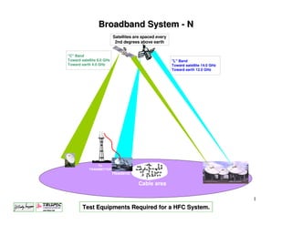
  • 1. Broadband System - N Satellites are spaced every 2nd degrees above earth "C" Band Toward satellite 6.0 GHz "L" Band Toward earth 4.0 GHz Toward satellite 14.0 GHz Toward earth 12.0 GHz TV TRANSMITTER Headend Cable area 1 Test Equipments Required for a HFC System.
  • 2. RF test equipment can be divided in two sections. • Single equipment capable of reading the strength of a Television Channels. • Multi function meter, capable of reading; • TV channel signal strength • Digital signal (Power meter) • Multi channel reading (Slope or Tilt) • Spectral view of all the channels carried by an HFC system • C/N measurement. • Distortion measuring (C-N, CTB and CSO) • Frequency Response (Peak & Valley response) • QAM reading (BER, MER and FEC) • Return alignment tool. (Response and Ingress) • Ingress reading (Leakage) 2
  • 3. Filed Strength Meter capable of reading Television Channels. This equipment read the level of a single TV channel or a single FM music channel. These level can be read as TV channel or Frequency. They also give you the difference in level between the Video and Audio of TV channel. They can usually read signal from: 5 to 870 MHz. 3
  • 4. Field Strength Meter Video 300 to 400 KHz Most FSM read between 300 to 400 KHz of band 6.0 MHz Audio width. 0 300 to 400 KHz -10 How it is display on the -20 Field Strength Meter -30 dB -40 -50 -60 -70 3.59 MHz 4.5 MHz 4
  • 5. Multi Function FSM Multi function meter can be classified in two types; •Meter for customer installation •Meter for complete system verification. Installation FSM Multifunction HFC Analyzer 5
  • 6. Multi Function FSM Installation FSM 6
  • 7. Installation FSM The Model One from Trilithic is an installation meter that can perform the following functions. Single channel Single channel Digital signal reading Spectral View Strength 7
  • 8. Installation FSM The Model One from Trilithic is an installation meter that can perform the following functions. Favourites channels AC – DC Tilt View View Reading 8
  • 9. Installation FSM Below are examples of a signal been read by the Model One F.S.M. Analog TV channel QAM TV channel 9
  • 11. Meter for complete system verification. BLOCK DIAGRAM RF INPUT RF FRONT END DISPLAY MULTI-BW I.F. HIGH-SPEED DISPLAY DRIVER 12-BIT DIGITIZER DIRECT DIGITAL “POWER - PC” and SYNTHESIZER DSP PROCESSORS KEYPAD ETHERNET / RS-232C COMMUNICATIONS 11
  • 12. Meter for complete system verification. Standard functions. Single Channel Measurement - NTSC or PAL video, audio, SAP. - Audio demodulation. - Hum (50/60Hz, 100/120Hz, 1KHz L.P.) - C/N on active channel channels. - CTB, CSO. - Depth of Modulation. - QAM Haystack with power. - Toggle to 1-chan. spectrum mode. 12
  • 13. Meter for complete system verification. - Full Plan Measurement. - Level, CTB, CSO, Hum and C/N on designated channels - all if possible - Tilt / 8 Channel Plan - Auto Gain and Tilt calculation - FCC Test - Drop, Block and Tap - - - 13
  • 14. Meter for complete system verification. - QAM, QPSK - Constellation, MER, pre and post BER, C/(N+I)? - Spectrum under active signal 14
  • 15. Meter for complete system verification. QAM-DOCSIS channel, measuring; Level, MER and BER. 64 QAM DOCSIS signal. 256 QAM DOCSIS signal. 15
  • 16. Meter for complete system verification. · RSVP Up to 8 frequencies · SSR New combined displays · Ingress comparison: SST vs. current location 16
  • 17. Meter for complete system verification. Spectrum Analyzer Option: · Span 0, 100 KHz to 860 MHz · Resolution Bandwidth 10 KHz to 3 MHz in 1,3 format · Video Bandwidth 100 Hz to 3 MHz in 1,3 format · Spur free Display Range 60 dB · Noise floor -50 dBmV in 10 KHz resolution · Display smoothed to approximate an analog analyzer 17
  • 18. Meter for complete system verification. 4 8 d B m V 4 7 4 6 4 5 4 4 4 3 4 2 4 1 4 0 3 9 3 8 3 7 5-40 MHz 18
  • 19. Meter for complete system verification. Spectrum Analyzer Measurement. 4 8 d B m V 4 7 4 6 4 5 4 4 4 3 4 2 4 1 4 0 3 9 3 8 3 7 5-40 MHz 19
  • 20. Meter for complete system verification. 4 8 d B m V 4 7 4 6 4 5 4 4 4 3 4 2 4 1 4 0 3 9 3 8 3 7 5-40 MHz 20
  • 21. Fiber Optic Test Equipments 21
  • 22. HFC System Since a HFC system requires two types of communications, one type been fiber optic and the other one been coaxial cable, two type of test equipments are require to test both sections of a system. •Test equipment for coaxial cable distribution. •Test equipment for fiber optic communication. 22
  • 23. Test equipments for fiber optic communication Test equipments required for the fiber optic section are the following; •Power meter. •Light Source. •OTDR (Optical Time Domain Reflectometer). •OSA (Optical Spectrum Analyser). •Talk Set. •Visual Fault Locator •Optical Fiber Identifier. •Optical Scope. •PMD Analyzer. 23
  • 24. Power meter. Power meter are required to measure the power output of the optic transmitting equipment, the input of the receiving equipment and the actual loss of a fiber optic link. GN-6025 Freq.: 800 to 1700 nm. +5 to – 70 dBm GN-6025C * Freq.: 800 to 1700 nm. +20 to – 60 dBm * Best for HFC system. 24
  • 25. Light Source. Optical Light Source gives a calibrated light output that can be used for testing a fiber link, when no other light signal are available. GN-6250 * 1310-1550 nm. - 8.0 dBm GN-6260 1550-1625 nm - 8.0 / - 5.0 dBm *Best for HFC system. 25
  • 26. OTDR (Optical Time Domain Reflectometer) OTDR are used to check continuity and signal loss on fiber optic link. CMA-4000-MDK-1 •8.4” Colour Matrix Display. •30/28 dB 1310/1550 nm. •Dual Single Opt. Module. •Hard Transit Case. •Network VisionNet Plus Software. 26
  • 27. OTDR (Optical Time Domain Reflectometer) OTDR are used to check continuity and signal loss on fiber optic link. CMA-4000-DK-2-X •8.4” Colour Matrix Display. •36/34 dB 1310/1550 nm. •Built-in-Hard drive. •Built in Light Source. •Dual Single Opt. Module. •Hard Transit Case. •Network VisionNet Plus Software. 27
  • 28. OTDR (Optical Time Domain Reflectometer) OTDR are used to check continuity and signal loss on fiber optic link. CMA-4000-DK-3-X •8.4” Colour Matrix Display. •40 dB 1310/1550 nm. •Built-in-Hard drive. •Dual Single Opt. Module. •Built in Light Source. •Hard Transit Case. •Network VisionNet Plus Software. 28
  • 29. OTDR (Optical Time Domain Reflectometer) Printed view of two fiber optic links measurements. 29
  • 30. The Growing Demand for Data Transport It is clear, as we approach the 21th century the remarkable evolution in information services in our society. This revolution in information has been promoted by; • Higher number of long distance phone call • Internet traffic • Multimedia services • Transport of medical picture at high speed • Financial exchanges (Credit card, Direct payments etc.) • Demand for more television signal These are the reason, why information services need increase in capacity 30
  • 31. Capacity of a fiber optic network Since to-day, the capacity of a fiber optic network is limited to 10 Gbps, soon to be 40 Gbps, we must find other way to increase the fiber optic’s capacity Let have a look at the possibility of augmenting the capacity of the network. 31
  • 32. Ways of Increasing the Capacity of a Fiber Optic System. * By installing more fiber. * By augmenting the fiber optic capacity. * By using the technology of CWDM or DWDM. 32
  • 33. Installing New Fiber Optic Installing new fiber optic can be very expensive and difficult in areas like; •Big city. •Submarine cable. •Underground duck been completely full. •Lack of space in CO (Central Office) 33
  • 34. SONET transmission capacity Optic Mb/s Tel. Conv. TV ch. DS0 0.064 1 * T1 1.54 24 * DS3 44.74 672 * OC-3 155.52 2,016 2 OC-12 622.08 8,064 12 OC-48 2,488.32 32,256 48 OC-96 4,976.64 77,760 55 OC-192 9,953.28 155,520 111 * Only slow scan picture. 34
  • 35. The DWDM Technology The DWDM technology, consist on transmitting many optical waves on the same fiber optic. Dense Wave Division Multiplexing      35
  • 36. Thirty Two Wavelengths DWDM Frequencies. 36
  • 37. OSA (Optical Spectrum Analyser). 37
  • 38. OSA (Optical Spectrum Analyser). OSA are used to measure Carrier to Noise, Signal amplitude, EDFA’s flatness and bandwidth response and signal frequency. Model CMA4791 Wavelength: 1520 - 1570 nm Power Range: +20 to –60 dBm Power Range: +10 to –70 dBm opt. Channel table: 256 channels. 38
  • 39. Talk Set. Talk set are used to communicates between the field technician and the central office people over fiber optic. Optical Specifications For Full-duplex OVS-6000 1310 nm Range: >30 dB OVS-6100 1310 nm Range: >50 dB Above on single-mode fiber. single- 39
  • 40. Visual Fault Locator The VFL-670 works at 670 nm with an output of –4.0 dBm. It is capable of a distance of 2 kilometres. It give a RED visible light, where there is a break or a bad connected installed. The unit work for multimode and single mode fiber optic. 40
  • 41. Optical Fiber Connector Inspection. The FS-X00 Fiberscope is ideal for inspecting optic connector. This unit will give a 200X or 400X view for multimode and single mode fiber connector. You need one of the following ADAPTER: FC-APC, ST, SC-APC, or D4. 41
  • 42. Problems with Fiber Optic Transport System. 42
  • 43. Two majors problems with Fiber optic transport System • Chromatic Dispersion. • Polarization Mode Dispersion. 43
  • 44. What is Dispersion. The spreading or broadening of light pulses as they propagate through the fiber 44
  • 45. Digital Communication Bit Times Dispersion SONET SDH Transmission Rate Bit Time Limit OC-1 OC- 51.84 Mb 19.29 ns 2 ns OC-3 OC- STM-1 STM- 155.52 Mb 6.43 ns 640 ps OC-12 OC- STM-4 STM- 622.08 Mb 1.61 ns 160 ps OC-24 OC- 1244.16 Mb (1.2 Gb) 803.76 ps 80 ps OC-48 OC- STM-16 STM- 2488.32 Mb (2.4 Gb) 401.88 ps 40 ps OC-192 OC- STM-64 STM- 9953.28 Mb (10 Gb) 100.47 ps 10 ps OC-768 OC- STM-256 STM- 39,813.12 Mb (40 Gb) 25.12 ps 2 ps Above are SONET •Transmission Rate •Bit Time •Dispersion Limit 45
  • 46. Eye Diagrams - What They Are • For each bit time, there are 8 possibles conditions: 1 bit time 0 0 0 1 0 0 0 0 1 1 0 1 0 1 0 1 1 0 0 1 1 1 1 1 • Combine (overlap) them for an eye diagram 46
  • 47. Typical Good and Bad Eye Diagram (High Bit Error Rate) One Level Sample Window Zero Level 1 bit time One Level Sample Window Zero Level 1 bit time 47
  • 48. What is Polarization Mode Dispersion What is Polarization Mode Dispersion Polarization Mode Dispersion is basically due to the fact that different polarizations of light travel at different speeds. Off Center Different Size Non-Circular Above are some the majors causes of PMD. 48
  • 49. Differential Delay The difference in speed between the two cars (or two wavelengths of light) causes them to arrive at the end at different times. The longer the distance, the more 65 mph time difference between them. 55 mph 65 mph Start 0 sec. diff 55 mph 65 mph After 1 mille 10 sec. diff 55 mph After 20 mille 200 sec. diff 49
  • 50. Reading of Chromatic Dispersion. Above are reading of Chromatic Dispersion between 1260 to 1560 nanometre. 50
  • 51. Chromatic Dispersion. +20 - - Dispersion (psnmxkm) Standard Single-Mode Fiber +10 - - 0 - - DWDM band -10 - - D-NZ-DSF -20 - - 1300 1400 1500 1600 Wavelength (nm) As there are two types of fiber optic with different type of Chromatic Dispersion. Above is the Chromatic Dispersion for standard fiber and NZ- DSF (None Zero Chromatic Dispersion). This type aof fiber optic is used for long distance transport and utilized the 1550 nm light frequency. 51
  • 52. The Results of PMD. Delay caused by PMD. 52
  • 53. PMD Analyzer The PMD440 is capable of measuring PMD (Polarisation Mode Dispersion). PMD can occur at 1310 and 1550 nm. PMD will be one of the major problem with fiber optic for long distance and high speed data transmission. 53
  • 54. Reading PMD Results. Good PMD Measurement Bad PMD Measurement 54
  • 55. PMD and HFC System. A HFC system requires the following PMD requirements: For 1310 nm is: 0.5 ps sk-km. For 1550 nm is: 0.2 ps sk-km. Any worse PMD readings than the above, would cause a bad CSO (Composite Second Order) reading at the NODE. 55
  • 56. 56