Network technology Paper 2
•Télécharger en tant que DOCX, PDF•
1 j'aime•673 vues

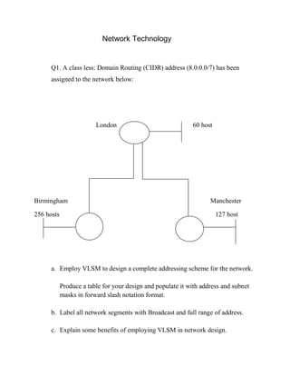
This document discusses network addressing and routing. It presents a network with three segments in London, Birmingham, and Manchester of varying host sizes. It asks the reader to: a) Design an addressing scheme using VLSM for the network and populate a table with subnets and masks b) Label the network segments with addresses and broadcasts c) Explain benefits of VLSM It then asks the reader to determine the routing protocol and sketch the topology for a network routing between two interfaces. Finally, it provides input/output layer data to sketch a network diagram showing IP addresses, MAC addresses, and interfaces between devices.

Recommandé
Contenu connexe
Tendances
Tendances (20)
En vedette
En vedette (20)
Similaire à Network technology Paper 2
Similaire à Network technology Paper 2 (20)
Plus de Sachii Dosti
Dernier
Dernier (20)
Network technology Paper 2
- 1. Network Technology Q1. A class less: Domain Routing (CIDR) address (8.0.0.0/7) has been assigned to the network below: London Birmingham 256 hosts 60 host Manchester 127 host a. Employ VLSM to design a complete addressing scheme for the network. Produce a table for your design and populate it with address and subnet masks in forward slash notation format. b. Label all network segments with Broadcast and full range of address. c. Explain some benefits of employing VLSM in network design.
- 2. Bits Total host Total Subnets 1 2 2 4 3 6 4 8 5 16 6 32 7 64 8 126 9 256 10 512 11 1024 12 2048
- 3. New Subnet mask 8.0.0.0/23 255.255.254.0 512 hosts 9 host bits 7 network bits 16 subnet bits 16 bits = 65536
- 4. 8.0.0.0/23 8.0.2.0/23 8.0.2.0/24 8.0.2.1/24 (127 Total hosts) 256 Total 8.0.2.254/24 8.0.2.255/24 8.0.3.0/24 256 Total 512 512 Total Total 8.0.1.254/23 8.0.1.255/23 Advantages of VLSM Standard subnetting benefits include: 1. 2. 3. 4. Structure Performance Management Scalable VLSM 1. Reduces address space wastage 2. Reduce size of routing tables. 8.0.3.1 8.0.3.62 BC.63 8.0.3.64/26 8.0.3.128/26 8.0.3.192/26
- 5. Q2. Determine the route to a destination network given that packets to the remote network pass through two fast Ethernet ports. The delay of a fast Ethernet port is 100MS 256 X [ 107/105 + 200/10 ] 256X120 = 30720 Show IP route C 192.168.1.0/24 is a directly connected Fast Ethernet 0/0 C 192.168.3.0/24 is a directly connected Fast Ethernet 0/1 D 192.168.2.0/24 [90/30720] via is a directly connected Fast Ethernet 0/0 EIGRP AA Metric = Administrative distance a. Determine the dynamic routing protocol active on the router. b. Sketch the network topology using the information in the table. Label all network segments with their network address. Indicate suitable IP addresses for all interfaces on connected networks.
- 6. 192.168.1.0/24 192.168.3.1/24 192.168.1.1/24 192.168.2.1/24 192.168.3.0/24 R1 R2 ---------------------- 192.168.1.2/24 192.168.2.0/24 Fast Ethernet 0/1 Fast Ethernet0/0 A DISTANCE 120 100 90 110 115 PROTOCOL RIP IGRP EIGRP OSPF ISIS
- 7. INPUT LAYAR DATA OUTPUT LAYAR DATA Source IP = 192.168.10.3 Source IP = 192.168.10.3 Destination IP = 192.168.20.3 Destination IP = 192.168.20.3 Source MAC = 000C. CF7C. 4B78 Source MAC = 00E0.F75A.7604 Destination MAC = 00ED. F75A.7601 Destination MAC = 00ED. F983.B5A6 LAYER 1 PORT Fast Ethernet 0/0 LAYER 1 PORT Fast Ethernet 0/1 (a) Sketch the network diagram using the data in the tables above. Assume connected interfaces on the Layer device are configured with the first usable IP address on their respective networks. (b) Assume the source and destination devices are PC’s and show their IP address on your diagram. (c) Show the MAC address of all devices show in your diagram.
- 8. Answer. Fast Ethernet 0/0 Fast Ethernet 0/1 00E0.F75A.7601 0de0.F75A.7604 X Over Cable PC PC 192.168.10.3 192.168.20.3 000C.CF7C.4B78 00ED.F983.B5A6