MC0083 – Object Oriented Analysis &. Design using UML - Master of Computer Science - MCA - SMU DE
•Télécharger en tant que DOCX, PDF•
2 j'aime•1,601 vues


Recommandé
Recommandé
Contenu connexe
Tendances
Tendances (20)
Similaire à MC0083 – Object Oriented Analysis &. Design using UML - Master of Computer Science - MCA - SMU DE
Similaire à MC0083 – Object Oriented Analysis &. Design using UML - Master of Computer Science - MCA - SMU DE (20)
Plus de Aravind NC
Plus de Aravind NC (10)
Dernier
Dernier (20)
MC0083 – Object Oriented Analysis &. Design using UML - Master of Computer Science - MCA - SMU DE
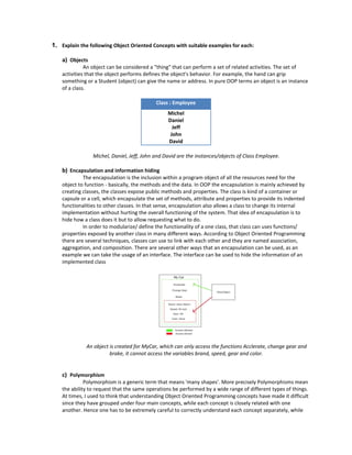
- 1. 1. Explain the following Object Oriented Concepts with suitable examples for each: a) Objects An object can be considered a "thing" that can perform a set of related activities. The set of activities that the object performs defines the object's behavior. For example, the hand can grip something or a Student (object) can give the name or address. In pure OOP terms an object is an instance of a class. Class : Employee Michel Daniel Jeff John David Michel, Daniel, Jeff, John and David are the instances/objects of Class Employee. b) Encapsulation and information hiding The encapsulation is the inclusion within a program object of all the resources need for the object to function - basically, the methods and the data. In OOP the encapsulation is mainly achieved by creating classes, the classes expose public methods and properties. The class is kind of a container or capsule or a cell, which encapsulate the set of methods, attribute and properties to provide its indented functionalities to other classes. In that sense, encapsulation also allows a class to change its internal implementation without hurting the overall functioning of the system. That idea of encapsulation is to hide how a class does it but to allow requesting what to do. In order to modularize/ define the functionality of a one class, that class can uses functions/ properties exposed by another class in many different ways. According to Object Oriented Programming there are several techniques, classes can use to link with each other and they are named association, aggregation, and composition. There are several other ways that an encapsulation can be used, as an example we can take the usage of an interface. The interface can be used to hide the information of an implemented class An object is created for MyCar, which can only access the functions Acclerate, change gear and brake, it cannot access the variables brand, speed, gear and color. c) Polymorphism Polymorphism is a generic term that means 'many shapes'. More precisely Polymorphisms mean the ability to request that the same operations be performed by a wide range of different types of things. At times, I used to think that understanding Object Oriented Programming concepts have made it difficult since they have grouped under four main concepts, while each concept is closely related with one another. Hence one has to be extremely careful to correctly understand each concept separately, while
- 2. understanding the way each related with other concepts. In OOP the polymorphisms is achieved by using many different techniques named method overloading, operator overloading and method overriding. Here the draw() function can be used to draw a circle, a square and a triangle. This is called polymorphism. 2. Explain the following Object Oriented Methodologies: a) Rumbaugh et al.’s Object Modeling Technique The Object Modeling Technique (OMT) presented by Jim Rumbaugh and his co-workers describes a method for the analysis, design, and implementation of system using an object-oriented technique. OMT is a fast, intuitive approach for identifying and modeling all the objects making up a system. Details such as class attributes, method, inheritance, and association also can be expressed easily. The dynamic behavior of objects within a system can be described using the OMT dynamic model. This model lets you specify detailed state transitions and their descriptions within a system. Finally, a process description and consumer-producer relationships can be expressed using OMT’s functional model. OMT consists of four phases, which can be performed iteratively: Analysis - The results are objects and dynamic and functional models. System design - The results are a structure of the basic architecture of the system along with high-level strategy decisions. Object design - This phase produces a design document, consisting of detailed objects static, dynamic, and functional models. Implementation - This activity produces reusable, extendible, and robust code. OMT separates modeling into three different parts: An object model, presented by the object model and the data dictionary. A dynamic model, presented by the state diagrams and event flow diagrams. A functional model, presented by data flow and constraints. The object model - The object model describes the structure of objects in a system: their identity, relationships to other object attributes, and operations. The object diagram contains classes interconnected by association lines. Each class represents a set of individual objects. The association lines establish relationships among the classes. Each association line represents a set of links from the objects of one class to the objects of another class. The boxes represent classes and the filled triangle represents specialization. Association between Account and Transaction is one to many; since one account can have many transactions, the filled circle represents many (zero or more). The relationship between Client and Account classes is one to one: A client can have only one account and account can belong to only one person (in this model joint accounts are not allowed).
- 3. The OMT object model of a bank system. The OMT dynamic model - OMT provides a detailed and comprehensive dynamic model, in addition to letting you depict states, transitions, events, and actions. The OMT state transition diagram is a network of states and events. Each state receives one or more events, at which time it makes the transition to the next state. The next state depends on the current state as well as the events. State transition diagram for the bank application user interface. The OMT functional model - The OMT data flow diagram (DFD) shows the flow of data between different processes in a business. An OMT DFD provides a simple and intuitive method for describing business processes without focusing on the details of computer systems. Data flow diagrams use four primary symbols: The process is any function being performed. The data flow shows the direction of data element movement. The data store is a location where data are stored. An external entity is a source or destination of a data element. b) The Booch Methodology The Object Modeling Technique (OMT) presented by Jim Rumbaugh and his co-workers describes a method for the analysis, design, and implementation of a system using an object-oriented technique. OMT is a fast, intuitive approach for identifying and modeling all the objects making up a system. Details such as class attributes, method, inheritance, and association also can be expressed easily. The dynamic behavior of objects within a system can be described using the OMT dynamic model. This model lets you specify detailed state transitions and their descriptions within a system. Finally, a process description and
- 4. consumer-producer relationships can be expressed using OMT’s functional model. OMT consists of four phases, which can be performed iteratively: Analysis. The results are objects, dynamic and functional models. System design. The results are a structure of the basic architecture of the system along with highlevel strategy decisions. Object design. This phase produces a design document, consisting of detailed objects static, dynamic, and functional models. Implementation. This activity produces reusable, extendible, and robust code. OMT separates modeling into three different parts: An object model, presented by the object model and the data dictionary. A dynamic model, presented by the state diagrams and event flow diagrams. A functional model, presented by data flow and constraints. The object model - The object model describes the structure of objects in a system: their identity, relationships to other object attributes, and operations. The object diagram contains classes interconnected by association lines. Each class represents a set of individual objects. The association lines establish relationships among the classes. Each association line represents a set of links from the objects of one class to the objects of another class. The OMT dynamic model provides a detailed and comprehensive dynamic model, in addition to letting you depict states, transitions, events, and actions. The OMT state transition diagram is a network of states and events. Each state receives one or more events, at the time it makes the transition to the next state. The next state depends on the current state as well as the events. 3. Describe the following UML notations: a. Diagram Elements (Graphs, Drawing paths ...) Graphs Most UML diagrams and some complex symbols are graphs containing nodes connected by paths. The information is mostly in the topology, not in the size or placement of the symbols (there are some exceptions, such as a sequence diagram with a metric time axis). There are three kinds of visual relationships that are important: connection (usually of lines to 2-d shapes), containment (of symbols by 2-d shapes with boundaries), and visual attachment (one symbol being “near” another one on a diagram). These visual relationships map into connections of nodes in a graph, the parsed form of the notation. UML notation is intended to be drawn on 2-dimensional surfaces. Some shapes are 2- dimensional projections of 3-d shapes (such as cubes), but they are still rendered as icons on a 2-dimensional surface. In the near future, true 3-dimensional layout and navigation may be possible on desktop machines; however, it is not currently practical. There are basically four kinds of graphical constructs that are used in UML notation: Icons - An icon is a graphical figure of a fixed size and shape. It does not expand to hold contents.
- 5. 2-d Symbols - Two-dimensional symbols have variable height and width and they can expand to hold other things, such as lists of strings or other symbols. Paths - Sequences of line segments whose endpoints are attached. Conceptually a path is a single topological entity, although its segments may be manipulated graphically. Strings - Present various kinds of information in an “unparsed” form. UML assumes that each usage of a string in the notation has a syntax by which it can be parsed into underlying model information. Drawing Paths - A path consists of a series of line segments whose endpoints coincide. The entire path is a single topological unit. Line segments may be orthogonal lines, oblique lines, or curved lines. Certain common styles of drawing lines exist: all orthogonal lines, or all straight lines, or curves only for bevels. The line style can be regarded as a tool restriction on default line input. When line segments cross, it may be difficult to know which visual piece goes with which other piece; therefore, a crossing may optionally be shown with a small semicircular jog by one of the segments to indicate that the paths do not intersect or connect (as in an electrical circuit diagram). In some relationships (such as aggregation and generalization) several paths of the same kind may connect to a single symbol. b. Model Management A package is a grouping of model elements. Packages themselves may be nested within other packages. A package may contain both subordinate packages and ordinary model elements. Some packages may be Subsystems or Models. The entire system description can be thought of as a single high-level subsystem package with everything else in it. All kinds of UML model elements and diagrams can be organized into packages. There are several predefined stereotypes of Model and Subsystem. See the metamodel document for details. In particular, the stereotype «system» of Subsystem denotes the entire set of models for the complete system being modeled; it is the root of the package hierarchy and the only model element that is not owned by some other model element. A package is shown as a large rectangle with a small rectangle (a “tab”) attached on one corner (usually the left side of the upper side of the large rectangle). It is a manila folder shape. If contents of the package are not shown, then the name of the package is placed within the large rectangle. A tool may also show visibility by selectively displaying those elements that meet a given visibility level, e.g., all of the public elements only. It is expected that packages with large contents will be shown as simple icons with names, in which the contents may be dynamically accessed by “zooming” to a detailed view. A package symbol maps into a Package element. The name on the package symbol is the name of the Package element. If the package has a keyword that is a predefined keyword, then the package symbol maps into the corresponding subclass of Package or into the corresponding stereotype of Package; otherwise it maps into a user-defined stereotype of Package. c. General Extension Mechanisms The General purpose mechanisms can be applied to any modeling element. The semantics of a particular use depends on a convention of the user or an interpretation by a particular constraint language or programming language, therefore they constitute an extensibility device for UML. A constraint is a semantic relationship among model elements that specifies conditions and propositions that must be maintained as true (otherwise the system described by the model is invalid, with Consequences that are outside the scope of UML). Certain kinds of constraints (such as an associa-
- 6. tion “or” constraint) are predefined in UML, others may be user-defined. A comment is a text string (including references to human-readable documents) attached directly to a model element. This is syntactically equivalent to a constraint written in the language “text” whose meaning is significant to humans but which is not conceptually executable. A stereotype is, in effect, a new class of modeling element that is introduced at modeling time. It represents a subclass of an existing modeling element with the same form (attributes and relationships) but with a different intent. Generally a stereotype represents a usage distinction. A stereotyped element may have additional constraints on it from the base class. It is expected that code generators and other tools will treat stereotyped elements specially. Stereotypes represent one of the built-in extensibility mechanisms of UML 4. What are the various classes in class stereotypes of software development process? Explain in detail. Analysis classes come in the following three kinds: 1) entity, 2) control, and 3) boundary. Design classes are not stereotyped in the process. a) Entity - Entity is a class that is passive; that is, it does not initiate interactions on its own. An entity object may participate in many different use case realizations and usually outlives any single interaction. b) Control - Control is a class, an object of which denotes an entity that controls interactions between collections of objects. A control class usually has behavior specific for one use case and a control object usually does not outlive the use case realizations in which it participates. c) Boundary - A Boundary is a class that lies on the periphery of a system, but within it. It interacts with actors outside the system as well as objects of all three kinds of analysis classes within the system. d) Notation - Class stereotypes can be shown with keywords in guillemots. They can also be shown with the following special icons. 5. Describe the goals and scope of UML with suitable examples. The primary design goals of the UML are as follows: Provide users with a ready-to-use, expressive visual modeling language to develop and exchange meaningful models.
- 7. Furnish extensibility and specialization mechanisms to extend the core concepts. Support specifications that are independent of particular programming languages and development processes. Provide a formal basis for understanding the modeling language. Encourage the growth of the object tools market. Support higher-level development concepts such as components, collaborations, frameworks and patterns. Integrate best practices. These goals are, Provide users with a ready-to-use, expressive visual modeling language to develop and exchange meaningful models. It is important that the Object Analysis and Design (OA&D) standard support a modeling language that can be used ―out of the box‖ to do normal general-purpose modeling tasks. If the standard merely provides a meta-meta-description that requires tailoring to a particular set of modeling concepts, then it will not achieve the purpose of allowing users to exchange models without losing information or without imposing excessive work to map their models to a very abstract form. The UML consolidates a set of core modeling concepts that are generally accepted across many current methods and modeling tools. These concepts are needed in many or most large applications, although not every concept is needed in every part of every application. Specifying a meta-meta-level format for the concepts is not sufficient for model users, because the concepts must be made concrete for real modeling to occur. If the concepts in different application areas were substantially different, then such an approach might work, but the core concepts needed by most application areas are similar and should be supported directly by the standard without the need for another layer. Furnish extensibility and specialization mechanisms to extend the core concepts OMG expects that the UML will be tailored as new needs are discovered and for specific domains. At the same time, we do not want to force the common core concepts to be redefined or re-implemented for each tailored area. Therefore, we believe that the extension mechanisms should support deviations from the common case, rather than being required to implement the core modeling concepts themselves. The core concepts should not be changed more than necessary. Users need to be able to: ○ build models using core concepts without using extension mechanisms for most normal ○ ○ ○ ○ applications, add new concepts and notations for issues not covered by the core, choose among variant interpretations of existing concepts, when there is no clear consensus, Specialize the concepts, notations, and constraints for particular application domains. Support specifications that are independent of particular programming languages and development processes. The UML must and can support all reasonable programming languages. It must also and can support various methods and processes of building models. The UML can support multiple programming languages and development methods without excessive difficulty. Provide a formal basis for understanding the modeling language Because users will use formality to help to understand the language, it must be both precise and approachable; a lack of either dimension damages its usefulness. The formalisms must not require excessive levels of indirection or layering, use of low level mathematical notations distant from the modeling domain, such as set-theoretic notation, or operational definitions that are equivalent to programming an implementation. The UML provides a formal definition of the static format of the model using a meta model expressed in UML class diagrams. The Unified Modeling Language (UML) is a language for specifying, constructing, visualizing, and documenting the artifacts of a software-intensive system.
- 8. First and foremost, the Unified Modeling Language fuses the concepts of Booch, OMT, and OOSE. The result is a single, common, and widely usable modeling language for users of these and other methods. Secondly, the Unified Modeling Language pushes the envelope of what can be done with existing methods. As an example, the UML authors targeted the modeling of concurrent, distributed systems to assure the UML adequately addresses these domains. Thirdly, the Unified Modeling Language focuses on a standard modeling language, not a standard process. 6. What are the two ways of communicating with subsystem? Explain There are two ways of communicating with a subsystem, either by sending stimuli to the subsystem itself to be re-directed to the proper recipient inside the subsystem, or by sending stimuli directly to the recipient inside the subsystem. In the first case, an association is defined with the subsystem itself to enable stimuli sending. A subsystem can have generalizations to other subsystems, i.e., the public and protected elements in the contents of a subsystem as well as operations and receptions are also available to its heirs. A subsystem may offer a set of interfaces, i.e., for each operation defined in an interface, the subsystem offering the interface must have a matching operation, either as a feature of the subsystem itself or of a specification element. Profile: Profiles can contain stereotypes, tag definitions, and constraints. They can also contain data types that are used by tag definitions for informally declaring the types of the values that can be associated with tag definitions. Model: A model is a description of a physical system with a certain purpose, such as to describe logical or behavioral aspects of the physical system to a certain category of readers. Examples of different kinds of models are ‘use case,’ ‘analysis,’ ‘design,’ and ‘implementation,’ or ‘computational,’ ‘engineering,’ and ‘organizational’ each representing one view of a physical system. Thus, a model is an abstraction of a physical system. It specifies the physical system from a certain vantage point (or viewpoint); that is, for a certain category of stakeholders (for example, designers, users, or orders of the system), and at a certain level of abstraction, both given by the purpose of the model. A model is complete in the sense that it covers the whole physical system, although only those aspects relevant to its purpose; that is, within the given level of abstraction and vantage point, are represented in the model. Furthermore, it describes the physical system only once; that is, there is no overlapping; no part of the physical system is captured more than once in a model. A model consists of a containment hierarchy where the top-most package or subsystem represents the boundary of the physical system. This package/subsystem may be given the stereotype «topLevel» to emphasize its role within the model. It is possible to have more than one containment hierarchy within a model; that is, the model contains a set of top-most packages/subsystems each being the root of a containment hierarchy. In this case there is no single package/subsystem that represents the physical system boundary. The model may also contain model elements describing relevant parts of the system’s environment. The environment is typically modeled by actors and their interfaces. As these are external to the physical system, they reside outside the package/subsystem hierarchy. They may be collected in a separate package, or owned directly by the model. These model elements and the model elements representing the physical system may be associated with each other. A model may be a specialization of another model via a generalization relationship. This implies that all public and protected elements in the ancestor are also available in the specialized model under the same name and interrelated as in the ancestor. A model may import or access another model. Models may be nested. A large physical system may be composed by a set of subordinate physical systems together making up the large physical system.