"Lesotho Leaps Forward: A Chronicle of Transformative Developments"
Half wave rectifier
1. Lab Report # 02
Half & Full Wave Rectifiers
Half Wave Rectifier:
The half wave rectifier is a type of rectifier that rectifies only half cycle of the waveform
when the diode is in forward biased.
(OR)
Rectifier is a component of an electric circuit used to change alternating current to direct
current. Rectifiers are made in various forms, all operating on the principle that current
passes through them freely in one direction but only slightly or not at all in the opposite
direction.
To study the behavior of the half wave rectifier practically, I draw the circuit through the
Multisim Software, along all the basic components, i-e, Function Generator,
Oscilloscope, Diode & the load Resistor!
Circuit:
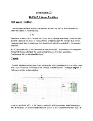
The half rectifier consist a step down transformer, a diode connected to the transformer
and a load resistance connected to the cathode end of the diode. The circuit diagram of
half wave rectifier is shown below:
In the above circuit XFG1 is the function generator which generates an AC signal of 01
KHz & the Diode D1 is connected in forward Biased to the Function Generator. XSC1 &
2. XSC2 are the Oscilloscope connected at the input terminal & output load resister to
measure the signal frequency through graph.
PROCEDURE:
Make a half wave rectifier circuit as shown in above circuit. After that connect the
oscilloscope with function generator and set a ac voltage having frequency of 1 kHz. Then a
output graph of the input voltage will be shown on The oscilloscope. Then connect the
function generator to circuit containing single diode and a load. In the +ve half cycle of ac
voltage the diode was forward biased, a positive half cycle of input voltage was passed
through diode. In the next half cycle the diode was in reverse biased and circuit behave like
an open circuit.
Input Signal Graph
From the graph above we can calculate the input Frequency, Time Period & V
peak-peak. The input Frequency is 1K Hz, Time Period is 207.092 ms & V p-p is 20V.
The signal is in sinusoidal form having both positive & negative cycles.
3. Input Signal
The above graph represent the input AC signal to the circuit, this signal is generated by
the Function Generator. We measure this input signal through Oscilloscope. This signal
is in form of sinusoidal wave having both the positive & negative cycles. The Vp-p is
20V. Voltes per division are 05V. The time period is 49.00ms.
Output Signal
4. The above graph present the output of the circuit. The signal is now in DC form. All
cycles appears in the positive half wave, as the circuit is design for full wave rectification
the negative half cycle also appear as a positive half cycle. The frequency of the output
signal is double to that of the signal input. The Vp-p is almost 08V, Volte’s per division
are 05V.
Output Signal Graph
5. The above graph represent the DC signal through the load Resister, after passing the
Diode D1, the half positive cycle appeared across the load resister & the negative half
cycle is disappeared! The Vp-p to across the load resister is now almost 10V. As 0.7V
dissipate across the diode & some across the resistor.
Full Wave Rectifier
The Full Wave rectifier converts the AC current to DC current, with both the half positive
& half negative half cycle conversion. The full wave rectifier allow the negative cycle with
positive value.
To study the behavior of the full wave rectifier I draw the following circuit through the
Multisim Software, with Oscilloscope, Function Generator, Bridge Rectifier & load
Resistor.
(OR)
A full wave rectifier consisting of four rectifiers connected in the form of a bridge, in
which two pairs of rectifying elements are used, each pair being in series and connected
to the input in opposite polarity to the other pair, the output being derived from the center
points of the two pairs.
COMPONENTS:
6. Bread Board
Jumper Wires
FUNCTION GENERATOR
OSCILOSCOPE
Resistor
Diode
Circuit Diagram
XSC1 & XCS2 are Oscilloscopes connected parallel to the input Function Generator &
Output load Resistor, to measure the input & output Signal through Graph!
The output graph before and after rectification is given below.