Russian Call Girls In Rajiv Chowk Gurgaon ❤️8448577510 ⊹Best Escorts Service ...
59446885 hvac
1. Steel manufacturing and air condition national association (SMACNA)
Width of the duct Gauge
0” to 36” - 26 G
37” to 48” - 24 G
49” to 72” - 22 G
73” to 84” - 20 G
85” to 108 - 18 G
Above 108” - 16 G
Chillers (Figures 3 and 4) are large central systems, which use the primary refrigerant to chill
water. The chilled water is then circulated through the building and serves as a “secondary
refrigerant” to cool the building air. Some chiller systems have “air cooled” condensers, but
many have water-cooled condensers coupled with a cooling tower to cool the condenser water.
Chillers are sold in sizes from about 12 tons to hundreds of tons, but, in contrast to unitary equipment, few units
are sold in the small sizes.
Also provided is a portable document format version of How to Buy an Energy-Efficient Air-Cooled Electric
Chiller (PDF 74 KB, 2 pp). Download Adobe Reader.
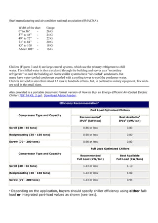
Efficiency Recommendationa
Part Load Optimized Chillers
Compressor Type and Capacity
Recommendedb
IPLVc
(kW/ton)
Best Availableb
IPLVc
(kW/ton)
Scroll (30 - 60 tons) 0.86 or less 0.83
Reciprocating (30 - 150 tons) 0.90 or less 0.80
Screw (70 - 200 tons) 0.98 or less 0.83
Full Load Optimized Chillers
Compressor Type and Capacity
Recommended
Full Load (kW/ton)
Best Available
Full Load (kW/ton)
Scroll (30 - 60 tons) 1.23 or less 1.10
Reciprocating (30 - 150 tons) 1.23 or less 1.00
Screw (70 - 200 tons) 1.23 or less 0.94
a
Depending on the application, buyers should specify chiller efficiency using either full-
load or integrated part-load values as shown (see text).
2. b
Values are based on standard rating conditions specified in ARI Standard 550/590-98.
Only packaged chillers (i.e., none with remote condensers) are covered.
• So the easy method is;
•••• calculate the room volume, length times width times ceiling height,
•••• divide room volume by 10 by shifting the decimal point one place to the left,
•••• get the size machine your room really needs (for 6 changes hourly), in cubic feet per minute.
____________________________________________________________________________________
STEP 1 - Calculate the volume of the area to be cleaned in cubic feet.
Length x Width x Height of area = Cubic Volume
STEP 2 - Divide the volume by 60 which represents minutes/hour.
Volume of Area ÷ 60 minutes in an hour = Cubic Feet Per Required for
ONE AIR CHANGE/HOUR
STEP 3 - Multiply the number of cfm's required in step #2 by the number of air changes desired from
the chart above.
Cubic Feet per Minute (#2) x #of Air Changes/hour (from chart above) =
Cubic Feet per Minute (CFM) required for this application
STEP 4 - Compare the Cubic Feet per Minute (CFM) required with the cfm rating of the units you are
considering. If the cfm required is more than any of the cfm ratings on an individual unit, you will need
more than one unit for that application.
CFM required for One Air Change/Hour x Air Changes/Hour Needed =
CFM's Needed for Your Application
For a faxed or mailed quotation, please send us the measurements of the area you wish to clean and the
number of air changes/hour you wish to accomplish. We'll do the work for you...just send us an e-mail.
EXAMPLE SPACE CALCULATION
Room dimensions: 50' x 100' x 10' ceiling
Type of area: Restaurant or Lounge
Air Changes Desired: 16 Air Changes/Hour (heavy pollution level)
Step 1 - Volume
50' x 100' x 10' = 50,000 cubic feet
Step 2 - Find Out CFM Required for One Air Change/Hour
3. 50,000 Cu. Ft.÷ 60 Minutes in an Hour = 833 cubic feet/Minute = ONE Air Change in an Hour
Step 3 - Total Volume Per Minute To Be Cleaned
833cfm x 16 air changes = 13,328 cfm
Step 4 - Number of Units Needed
13,328 cfm ÷ cfm of chosen unit = Number of Units Needed
(Model LA-2000): 13,328 cfm ÷ 2,100 cfm = 6.34 or 6-7 units
(Model LA-1400): 13,333 cfm ÷ 1,100 cfm = 12.09 or 12-13 units
The recommended ventilation rate for homes is 0.35 air changes per hour (ACH) or 15 cubic feet per minute per
person. For example, a 1,200 square foot home with 8-foot walls has an air volume of 9,600 cubic feet.
Obtaining an air changeof 0.35 per hour requires exchanging 0.35 x 9,600 = 3,360 cubic feet of air per hour.
This is an airflow rate of 3,360 ÷ 60 minutes per hour = 56cubic feet per minute.
Millions of people spend 90% of their day inside, so it's important that the buildings they occupy have a substantial amount of fresh,
outside air. ASHRAE 62 ventilation standards recommend that 15 to 60 cubic feet per minute (CFM) of outside air should be supplied
for every person within a building. Although this is just a recommendation,
Total Volume of Air in the Room ÷ 5 = Minimum Recommended CFM
The "magic number 5" in this formula is based on 12 changes per hour, divided by 60 minutes/hour to give us
the number of changes per minute. To apply this to your bathroom, multiply the width by the length by the
height to determine the total cubic feet...
Width x Length x Height = 6ft. x 8ft. x8ft. = 384 cubic feet
Divide the volume of your bathroom by 5 to find out the recommended CFM...
384 cubic feet ÷ 5 = 76.8 CFM or Cubic Feet per Minute
The first step when sizing for a ventilating fan is to determine the application. Decide whether you are
sizing for intermittent or continuous ventilation (see pages 6 and 7). If intermittent, determine which
application, (i.e. bathroom, kitchen or other). Use the following industry recommendations to
determine Air Changes per Hour (ACH) for your specific application.
Intermittent (spot) ventilation:
The Home Ventilating Institute (HVI) recommends the following Air Changes per Hour (ACH).
I. Bathrooms - 8 ACH or 1 CFM/sq ft
II. Kitchens - 15 ACH or 2 CFM/sq ft
Other Rooms - 6 ACH or .75 CFM/sq ft
Continuous (Whole House) Ventilation:
Most building codes have adopted the American Society of Heating, Refrigerating, and Air
Conditioning Engineers (ASHRAE) Standard 62. The most current version, ASHRAE 62.2-2004, calls
for continuous mechanical ventilation as shown below.
4. I. House or apartment - 7.5 CFM per person plus 1 CFM per 100 square feet
To calculate how many CFM of airflow is required to properly ventilate any room in your home, use the following
calculation.
• For an 8 foot ceiling take the square footage of the room and multiply it by 1.1.
(Example – 10' x 10' room with 8' ceilings:
10' x 10' = 100 square feet x 1.1 = 110 CFM’s)
• For any ceiling over 8 feet, take the height of the ceiling and multiply by .1375. Take this figure and multiply by the
square footage of the room. This will equal the recommended CFMs.
(Example – 10' x 12' room with 9' ceilings:
9' x .1375 =1.24 x 120 square feet = 149 CFMs.)
What does air change mean?
One air change occurs in a room when a quantity of air equal to the volume of the room
is supplied and/or exhausted.
Air change rates are units of ventilation that compare the amount of air moving through a
space to the volume of the space. Air change rates are calculated to determine how well a
space is ventilated compared to published standards, codes, or recommendations.
Air changes per hour (ACH) is the most common unit used. This is the volume of air
(usually expressed in cubic feet) exhausted or supplied every hour divided by the room
volume (also usually expressed in cubic feet).
Airflow is usually measured in cubic feet per minute (CFM). This is multiplied by 60 minutes
to determine the volume of air delivered per hour (in cubic feet).
To calculate room volume (in cubic feet), multiply room height (in feet) by the room area
(in square feet). Room area is the room width (in feet) times the room length (in feet).
ACH = airflow per hour = CFM X 60 minutes
room volume cubic feet
A room may have two airflow values, one for supply and another for exhaust. (The airflow
difference between these two values is called the offset.) To calculate the air change rate,
use the greater of the two airflow values.
Example of air change per hour calculation
An isolation room is 200 square feet in area and has a ceiling height of 9 feet. Airflow
measurements indicate a supply airflow of 360 CFM and an exhaust airflow of 480 CFM.
Does this room comply with the CDC recommendation that isolation rooms have a minimum
airflow rate:of 12 ACH for new construction?
Air change rate: 480 CFM X 60 = 16 ACH
200 ft2 X 9 ft
Exhaust air offset: 480 CFM – 360 CFM = 120 CFM
In conclusion, this room exceeds the CDC minimum requirement. The offset of 120 CFM
is made up by air from outside the room.
This information
Useful Formulas:
• Total Heat (BTU/hr) = 4.5 x cfm x ∆h (std. air)
• Sensible Heat (BTU/hr) = 1.1 x cfm x ∆t
• Latent Heat (BTU/hr) = 0.69 x cfm x ∆gr. (std. air)
5. • Total Heat (BTU/hr) = 500 x gpm x ∆t (water)
• BTU/hr = 3.413 x watts = HP x 2546 = Kg Cal x 3.97
• TONS = 24 x gpm x ∆t (water)
• GPM cooler = (24 x TONS) / ∆t (water)
• Fluid Mixture Tm = (Xt1 + Yt2) / X + Y (this works for air or water)
• Lb. = 453.6 grams = 7000 grains
• psi = ft. water/2.31 = in. hg/2.03 = in. water/27.7 = 0.145 x kPa
• Ton = 12,000 BTU/hr = 0.2843 x KW
• HP (air) = cfm x ∆p (in.H2O)/6350 x Eff.
• HP (water) = gpm x ∆p (ft.)/3960 x Eff.
• Gal. = FT
3
/7.48 = 3.785 Liters = 8.33 lb. (water) = 231 in.
3
• gpm= 15.85xL/S
• cfm = 2.119 x L/S
• Liter = 3.785 x gal = 0.946 x quart = 28.32 x ft
3
• Therm = 100,000 BTU = MJ/105.5
• Watt/sq. ft. = 0.0926 x W/M
2
• yd. = 1.094 x M
• ft. = 3.281 x M
• ft
2
= 10.76 x M
2
• ft
3
= 35.31 x M
3
• ft/min = 196.9 x M/S
• PPM (by mass) = mg/kg
Definitions
A BTU is defined as the amount of heat required to raise the temperature of one pound of liquid water
by one degree Fahrenheit. As is the case with the calorie, several different definitions of the BTU exist,
which are based on different water temperatures and therefore vary by up to 0.5%:
Conversions
One BTU is approximately:
1 054 – 1 060 J (joules)
252 – 253 cal (calories)
25 031 – 25 160 ft·pdl (foot-poundal)
778 – 782 ft·lbf (foot-pounds-force)
Other conversions:
In natural gas, by convention 1 MMBtu (1 million BTU, sometimes written "mmBTU") =
1.054615 GJ. Conversely, 1 gigajoule is equivalent to 26.8 m3
of natural gas at defined
temperature and pressure. So, 1 MMBtu = 28.263682 m3
of natural gas at defined
temperature and pressure.
1 standard cubic foot of natural gas yields ≈ 1030 BTU (between 1010 BTU and 1070 BTU,
depending on quality when burned)
[edit] Associated units
6. The BTU per hour (BTU/h) is the unit of power most commonly associated with the BTU.
1 watt is approximately 3.41 BTU/h
1000 BTU/h is approximately 293 W
1 horsepower is approximately 2,544 BTU/h
1 "ton of cooling", a common unit in North American refrigeration and air conditioning
applications, is 12,000 BTU/h. It is the amount of power needed to melt one short ton of ice in
24 hours, and is approximately 3.51 kW.
1 therm is defined in the United States and European Union as 100,000 BTU—but the U.S.
uses the BTU59 °F whilst the EU uses the BTUIT.
1 quad (energy) (short for quadrillion BTU) is defined as 1015
BTU, which is about one
exajoule (1.055 × 10¹⁸
J). Quads are used in the United States for representing the annual
energy consumption of large economies: for example, the U.S. economy used 99.75
quads/year in 2005. [1]. One quad/year is about 33.43 gigawatts.
The BTU should not be confused with the Board of Trade Unit (B.O.T.U.), which is a much larger
quantity of energy (1 kW·h, or about 3412 BTU).
Helpful HVAC Info:
Clues to BTU’s
Rule of thumb for Air Conditioning design
BTU – amount of heat required to raise the temperature of one pound of water one degree Fahrenheit. A ton of
refrigeration is equal to 12,000 BTU’s. That is the amount of heat required to melt a ton (2000 lbs) of ice at 32
degrees Fahrenheit.
Comfort cooling: estimate one ton of cooling for every 400 square feet of living space.
Commercial Process Cooling: estimate approximately one ton of cooling for every 250 square feet of space to
be conditioned.
Cooling People: People generate approximately 600 BTU’S per person. If you have 10 people in a room you
must therefore account for 10 x 600 = 6000 Btu’s
Cooling Equipment: check equipment specifications for the BTU or Wattage output, if that information is not
available check the equipment nameplate and calculate wattage with volts times amps ( Volts x Amps ) = Watts
Quick Cool Formula: Watts x 3.4 = BTU or ( Volts x Amps ) x 3.4 = BTU
Add up all of your equipment BTU’s and you will have an approximate load calculation of your cooling
requirements.
HVAC Formulas
The HVAC design formulas shown below are based upon normal conditions and should only be
used as a general guide. For extreme or demanding conditions, we recommend consulting with
7. an architect or qualified environmental engineer to design an HVAC system for your specific
requirements.
Heating
Heater sizing formula – 7 watts of heat per square foot of floor space
Example:
10’ x 20’ room = 200 square feet
200 sq. ft. x 7 = 1400 watts of heat required
(Note: 1 watt = approximately 3.4 BTU’s)
Ventilation
The ventilation required within a room depends on a couple of factors: 1) Occupancy -- the
number of people normally in the room; and 2) Usage – lunchrooms or conference rooms may
require more ventilation.
General rule of thumb – changing the air in the room every 10 minutes is sufficient
Example:
10’ x 20’ room with 8’ ceiling height = 10’x20’x8’ = (1600 cubic feet)
1600 cu. ft. / 10 minutes = 160 cu. ft. per minute (CFM); therefore,
A 160 CFM fan should be adequate for this room.
Note: If smoking is allow in the room, the air should be changed every three minutes.
Air Conditioning
Air conditioner sizing formula – 30 BTU’s of cooling per square foot of floor space
Example:
10’ x 20’ room = 200 square feet
200 sq. ft. x 30 BTU’s = 6,000 BTU’s of cooling required
If the room is going to be heavily occupied (i.e. lunchroom, conference room) or located near a
heat producing piece of equipment, the amount of air conditioning should be increased. A good
rule of thumb is to add 500 BTU’s for each person in the room.
Material extracted in whole or in part with permission and courtesy of Starrco.
Updated June 2007
CALCULATING COOLING CAPACITY
A good rule of thumb to estimate the amount of cooling capacity
you need is to multiply the area of floor space (ft2) by a factor of
10 and add 3,000.
For example, the amount of cooling capacity for a 20-foot by
20-foot room would be:
[400 ft2 x 10] + 3,000 = 7,000 Btu/hour
8. ENGINEERING DATA
1 ton a/c = 12,000 BTU per hour
1 Boiler HP = 42,000 BTU input (@ approx. 80% efficiency)
100 Boiler HP = 42 therm Input (@ approx. 80% efficiency)
100 lb Steam = 1 therm (approx.)
1 Engine HP = 10,000 BTU input (approx.)
1 British Thermal Unit = Energy required to raise the temperature of 1 lb. Mass
of water by 1° F
1 SCF natural gas = 1,000 BTU (approx.)
100 SCF natural gas = 1 therm (approx.)
1 MSCF natural gas = 1,000 scf 1 MSCF = 10 therm
1 Therm = 29.3 kilowatt hr
Standard Cubic Foot = Volume of gas at standard conditions
Standard conditions = 60° F @ 14.73 psia
SCFH = Volume flow rate per hour @ standard conditions
Degrees Celsius = 5/9 ( °F - 32)
ABBREVIATIONS
ACSH - actual cubic feet per hour
ACFM - actual cubic feet per minute
BTU - British thermal unit
MSCF - (thousand) standard cubic feet
N.O. - Normally open
N.C. - Normally closed
PSI - pounds per square inch
PSIA - pounds per square inch absolute
PSIG - pounds per square inch gauge
SCFH - Standard cubic feet per hour
w.c. - inches of water column
G - Gravity
H - Pressure drop
Q - Flow
T - Temperature
W - Flow rate
RULES OF THUMB - UNIT SIZING
Sizing Boiler Feed or Condensate Return ump Discharge Pressure:
1) If boiler < 50 psig, size pump to discharge 5 psig above working pressure.
2) If boiler > psig, size pump to discharge 10 psig above working pressure.
Sizing Boiler Feed or Condensate Return Pump Capacity:
1) Condensate pump = 2 x condensate return rate
2) Boiler Feed pump = 2 x boiler evaporation rate, or:
a) .14 GPM/BHP (on/off pumps)
b) .104 GPM/BHP (continuous running pumps)
Receiver Storage:
1) Size condensate receivers for 2 minute net storage capacity per return rate.
2) Size boiler feed receivers for system capacity (normally estimated at 10
minutes)
RULES OF THUMB - GENERAL
1 Ft3 Natural Gas = 1000 BTU
1 Therm Natural Gas = 100,000 BTU
9. 1 Unit Natural Gas = 10 Therms = 1,000,000 BTU
1 Ft3 Propane = 2,500 BTU
1 Gallon #2 Oil - 140,000 BTU
1 lb. Steam = 1000 BTU
1 BHP = 42,000 BTU / hr Input
1 BHP = 33,600 BTU / hr Output
1 KWH Electric = 3412 BTU
Normal Stack Temp on a 15 psig Steam Boiler = 375°F
Normal Stack Temp on a 150 psig Steam Boiler = 475°F
Normal Stack Temp on a 30 psig Hot Water Boiler = 340°F
1 psig = 2.31' Head
1 psig = 27.68" H20
Air Supply Required (in CFM) = 10.8 X BHP
Louver Size = 1 In2 per 4000 BTU (Input)
HVAC
Heating, ventilating, and air conditioning is based on the basic principles of thermodynamics, fluid mechanics,
and heat transfer, and to inventions and discoveries made by Michael Faraday, Willis Carrier, Reuben Trane,
James Joule, William Rankine, Sadi Carnot, and many others. The invention of the components of HVAC
systems goes hand-in-hand with the industrial revolution, and new methods of modernization, higher efficiency,
and system control are constantly introduced by companies and inventors all over the world.
The three functions of heating, ventilating, and air-conditioning are closely interrelated. All seek to provide
thermal comfort, acceptable indoor air quality, and reasonable installation, operation, and maintenance costs.
HVAC systems can provide ventilation, reduce air infiltration, and maintain pressure relationships between
spaces. How air is delivered to, and removed from spaces is known as room air distribution.[1]
10.8 Air-Conditioning
10.8.1 Air-conditioning is the application of methods for controlling the temperature of internal environments
for the purpose of: (a) promoting human health and comfort, (b) improving working efficiency, (c) maintaining
materials in the most suitable conditions for storage and manufacturing operations, and (d) supplying
conditioned air (hot or cold) for industrial process. Multistoreyed office, hotel and other buildings are air-
conditioned to increase working efficiency and to provide optimum thermal comfort of the occupants. Thermal
comfort depends on proper combination of dry bulb temperature, relative humidity and air velocity.
Air Change per Hour (ACH) :- The number of times per hour that the volume of a specific room or building is
supplied or removed from that space by mechanical and natural ventilation.
Air handler, or air handling unit (AHU) :- Central unit consisting of a blower, heating and cooling elements,
filter racks or chamber, dampers, humidifier, and other central equipment in direct contact with the airflow.
This does not include the ductwork through the building.
British thermal unit (BTU) :- Any of several units of energy (heat) in the HVAC industry, each slightly more than
1 kJ. One BTU is the energy required to raise one pound of water one degree Fahrenheit, but the many
different types of BTU are based on different interpretations of this “definition”. In the United States the
power of HVAC systems (the rate of cooling and dehumidifying or heating) is sometimes expressed in
BTU/hour instead of watts.
10. Chiller :- A device that removes heat from a liquid via a vapor-compression or absorption refrigeration cycle.
This cooled liquid flows through pipes in a building and passes through coils in air handlers, fan-coil units, or
other systems, cooling and usually dehumidifying the air in the building. Chillers are of two types; air-cooled or
water-cooled. Air-cooled chillers are usually outside and consist of condenser coils cooled by fan-driven air.
Water-cooled chillers are usually inside a building, and heat from these chillers is carried by recirculating water
to outdoor cooling towers.
Coil :- Equipment that performs heat transfer when mounted inside an Air Handling unit or ductwork. It is
heated or cooled by electrical means or by circulating liquid or steam within it. Air flowing across it is heated
or cooled.
Controller :- A device that controls the operation of part or all of a system. It may simply turn a device on and
off, or it may more subtly modulate burners, compressors, pumps, valves, fans, dampers, and the like. Most
controllers are automatic but have user input such as temperature set points, e.g. a thermostat. Controls may
be analog, or digital, or pneumatic, or a combination of these.
delta T :- delta T is a reference to a temperature difference. It is used to describe the difference in
temperature of a heating or cooling fluid as it enters and as it leaves a heat transfer device. This term is used
in the calculation of coil efficiency.
Fan-coil unit (FCU) :-A small terminal unit that is often composed of only a blower and a heating and/or
cooling coil (heat exchanger), as is often used in hotels, condominiums, or apartments.
Condenser :- A component in the basic refrigeration cycle that ejects or removes heat from the system. The
condenser is the hot side of an air conditioner or heat pump. Condensers are heat exchangers, and can
transfer heat to air or to an intermediate fluid (such as water or an aqueous solution of ethylene glycol) to
carry heat to a distant sink, such as ground (earth sink), a body of water, or air (as with cooling towers).
Constant air volume (CAV) :- A system designed to provide a constant air volume per unit time. This term is
applied to HVAC systems that have variable supply-air temperature but constant air flow rates. Most
residential forced-air systems are small CAV systems with on/off control.
Damper : - A plate or gate placed in a duct to control air flow by introducing a constriction in the duct.
Evaporator : - A component in the basic refrigeration cycle that absorbs or adds heat to the system.
Evaporators can be used to absorb heat from air (by reducing temperature and by removing water) or from a
liquid. The evaporator is the cold side of an air conditioner or heat pump.
Furnace : - A component of an HVAC system that adds heat to air or an intermediate fluid by burning fuel
(natural gas, oil, propane, butane, or other flammable substances) in a heat exchanger.
Fresh air intake (FAI) :- An opening through which outside air is drawn into the building. This may be to replace
air in the building that has been exhausted by the ventilation system, or to provide fresh air for combustion of
fuel.
Grille : -A facing across a duct opening, usually rectangular is shape, containing multiple parallel slots through
which air may be delivered or withdrawn from a ventilated space.
11. Heat load, heat loss, or heat gain :- Terms for the amount of heating (heat loss) or cooling (heat gain) needed
to maintain desired temperatures and humidities in controlled air. Regardless of how well-insulated and
sealed a building is, buildings gain heat from warm air or sunlight or lose heat to cold air and by radiation.
Engineers use a heat load calculation to determine the HVAC needs of the space being cooled or heated.
Louvers : - Blades, sometimes adjustable, placed in ducts or duct entries to control the volume of air flow. The
term may also refer to blades in a rectangular frame placed in doors or walls to permit the movement of air.
Makeup air unit (MAU) :- An air handler that conditions 100% outside air. MAUs are typically used in
industrial or commercial settings, or in once- through (blower sections that only blow air one-way into the
building), low flow (air handling systems that blow air at a low flow rate), or primary-secondary (air handling
systems that have an air handler or rooftop unit connected to an add-on makeup unit or hood) commercial
HVAC systems.
Packaged terminal air conditioner (PTAC) : -
An air conditioner and heater combined into a single, electrically-powered unit, typically installed
through a wall and often found in hotels.
Roof-top unit (RTU) : -An air-handling unit, defined as either "recirculating" or "once-through" design, made
specifically for outdoor installation. They most often include, internally, their own heating and cooling devices.
RTUs are very common in some regions, particularly in single-story commercial buildings.
Variable air volume (VAV) system : - An HVAC system that has a stable supply-air temperature, and varies the
air flow rate to meet the temperature requirements. Compared to CAV systems, these systems waste less
energy through unnecessarily-high fan speeds. Most new commercial buildings have VAV systems.
The most common units for heat are
• BTU - British Thermal Unit
• Calorie
• Joule
BTU - British Thermal Unit: - The unit of heat in the imperial system - the BTU - is
• the amount of heat required to raise the temperature of one pound of water through 1o
F (58.5o
F -
59.5o
F) at sea level (30 inches of mercury).
• 1 Btu (British thermal unit) = 1055.06 J = 107.6 kpm = 2.931 10-4
kWh = 0.252 kcal = 778.16 ft.lbf
= 1.0551010
ergs = 252 cal = 0.293 watt-hours
An item using one kilowatt-hour of electricity will generate 3412 BTU.
Calorie: - A calorie is
• the amount of heat required to raise the temperature of one gram of water 1o
C.
• 1 kcal = 4186.8 J = 426.9 kp.m = 1.163 10-3
kWh = 3.088 ft.lbf = 3.9683 Btu = 1000 cal
The calorie is outdated and commonly replaced by the SI-unit Joule.
Joule: - The unit of heat in the SI-system the Joule is
12. • the mechanical energy which must be expended to raise the temperature of a unit weight (2 kg)
of water from 0o
C to 1o
C, or from 32o
F to 33.8o
F.
• 1 J (Joule) = 0.1020 kpm = 2.778 10-7
kWh = 2.389 10-4
kcal = 0.7376 ft.lbf = 1 kg.m2
/s2
= 1 watt
second = 1 Nm = 1 ft.lb = 9.478 10-4
Btu
Chiller Refrigeration Tons
A chiller refrigeration ton is defined as:
1 refrigeration ton = 12,000 Btu/h = 3,025.9 k Calories/h
A ton is the amount of heat removed by an air conditioning system that would melt 1 ton of ice in 24 hours.
Cooling Tower Tons
A cooling tower ton is defined as:
1 cooling tower ton = 15,000 Btu/h = 3,782 k Calories/h
Heat Load and Water Flow
A water systems heat load in Btu/h can be simplified to:
h = cp ρ q dt
= 1 (Btu/lbm
o
F) 8.33 (lbm/gal) q (gal/min) 60 (min/h) dt (o
F)
= 500 q dt (1)
where
h = heat load (Btu/h)
cp = 1 (Btu/lbm
o
F) for water
ρ = 8.33 (lbm/gal) for water
q = water volume flow rate (gal/min)
dt = temperature difference (o
F)
Example - Water Chiller Cooling
Water flows with 1 gal/min and 10o
F temperature difference. The ton of cooling load can be calculated as:
Cooling load = 500 (1 gal/min) (10o
F) / 12,000
= 0.42 ton
The efficiency of chillers depends on the energy consumed. Absorption chillers are rated in fuel consumption per ton cooling.
Electric motor driven chillers are rated in kilowatts per ton cooling.
KW/ton = 12 / EER
KW/ton = 12 / (COP x 3.412)
13. COP = EER / 3.412
COP = 12 / (KW/ton) / 3.412
EER = 12 / KW/ton
EER = COP x 3.412
If a chillers efficiency is rated at 1 KW/ton, the COP=3.5 and the EER=12
Cooling Load in - kW/ton
The term kW/ton is common used for large commercial and industrial air-conditioning, heat pump and
refrigeration systems.
The term is defined as the ratio of the rate of energy consumption in kW to the rate of heat removal in
tons at the rated condition. The lower the kW/ton the more efficient the system.
kW/ton = Pc / Er (1)
where
Pc = energy consumption (kW)
Er = heat removed (ton)
Coefficient of Performance - COP
The Coefficient of Performance - COP - is the basic unit less parameter used to report the efficiency
of refrigerant based systems.
The Coefficient of Performance - COP - is the ratio between useful energy acquired and energy
applied and can be expressed as:
COP = Eu / Ea (2)
where
COP = coefficient of performance
Eu = useful energy acquired (btu in imperial units)
Ea = energy applied (btu in imperial units)
COP can be used to define both cooling efficiency or heating efficiency as for a heat pump.
14. • For cooling, COP is defined as the ratio of the rate of heat removal to the
rate of energy input to the compressor.
• For heating, COP is defined as the ratio of rate of heat delivered to the rate
of energy input to the compressor.
COP can be used to define the efficiency at a single standard or non-standard rated condition or a
weighted average seasonal condition. The term may or may not include the energy consumption of
auxiliary systems such as indoor or outdoor fans, chilled water pumps, or cooling tower systems. For
purposes of comparison, the higher the COP the more efficient the system.
COP can be treated as an efficiency where COP of 2.00 = 200% efficient For unitary heat pumps,
ratings at two standard outdoor temperatures of 47o
F and 17o
F (8.3o
C and -8.3o
C) are typically used.
Energy Efficiency Ratio - EER
The Energy Efficiency Ratio - EER - is a term generally used to define the cooling efficiency of unitary
air-conditioning and heat pump systems.
The efficiency is determined at a single rated condition specified by the appropriate equipment
standard and is defined as the ratio of net cooling capacity - or heat removed in Btu/h - to the total
input rate of electric energy applied - in watt hour. The units of EER are Btu/w.h.
EER = Ec / Pa (3)
where
EER = energy efficient ratio (Btu/W.h)
Ec = net cooling capacity (Btu/h)
Pa = applied energy (Watts)
This efficiency term typically includes the energy requirement of auxiliary systems such as the indoor
and outdoor fans and the higher the EER the more efficient is the system.
Definitions
A BTU is defined as the amount of heat required to raise the temperature of one pound of liquid water
by one degree Fahrenheit. As is the case with the calorie, several different definitions of the BTU exist,
which are based on different water temperatures and therefore vary by up to 0.5%:
Conversions
One BTU is approximately:
1 054 – 1 060 J (joules)
15. 252 – 253 cal (calories)
25 031 – 25 160 ft·pdl (foot-poundal)
778 – 782 ft·lbf (foot-pounds-force)
Other conversions:
In natural gas, by convention 1 MMBtu (1 million BTU, sometimes written "mmBTU") =
1.054615 GJ. Conversely, 1 gigajoule is equivalent to 26.8 m3
of natural gas at defined
temperature and pressure. So, 1 MMBtu = 28.263682 m3
of natural gas at defined
temperature and pressure.
1 standard cubic foot of natural gas yields ≈ 1030 BTU (between 1010 BTU and 1070 BTU,
depending on quality when burned)
[edit] Associated units
The BTU per hour (BTU/h) is the unit of power most commonly associated with the BTU.
1 watt is approximately 3.41 BTU/h
1000 BTU/h is approximately 293 W
1 horsepower is approximately 2,544 BTU/h
1 "ton of cooling", a common unit in North American refrigeration and air conditioning
applications, is 12,000 BTU/h. It is the amount of power needed to melt one short ton of ice in
24 hours, and is approximately 3.51 kW.
1 therm is defined in the United States and European Union as 100,000 BTU—but the U.S.
uses the BTU59 °F whilst the EU uses the BTUIT.
1 quad (energy) (short for quadrillion BTU) is defined as 1015
BTU, which is about one
exajoule (1.055 × 10¹⁸
J). Quads are used in the United States for representing the annual
energy consumption of large economies: for example, the U.S. economy used 99.75
quads/year in 2005. [1]. One quad/year is about 33.43 gigawatts.
The BTU should not be confused with the Board of Trade Unit (B.O.T.U.), which is a much larger
quantity of energy (1 kW·h, or about 3412 BTU).
Air-conditioning Basics
Most people think that air conditioners lower the temperature in their homes simply by pumping cool air in. What's really
happening is the warm air from your house is being removed and cycled back in as cooler air. This cycle continues until
your thermostat reaches the desired temperature.
An air conditioner is basically a refrigerator without the insulated box. It uses the evaporation of a refrigerant, like Freon,
to provide cooling. The mechanics of the Freon evaporation cycle are the same in a refrigerator as in an air conditioner.
According to the Merriam-Webster Dictionary Online, the term Freon is generically "used for any of various
nonflammable fluorocarbons used as refrigerants and as propellants for aerosols."
16. Diagram of a typical air conditioner.
This is how the evaporation cycle in an air conditioner works (See How Refrigerators Work for complete details on this
cycle):
1. The compressor compresses cool Freon gas, causing it to become hot, high-pressure Freon gas (red in the
diagram above).
2. This hot gas runs through a set of coils so it can dissipate its heat, and it condenses into a liquid.
3. The Freon liquid runs through an expansion valve, and in the process it evaporates to become cold, low-
pressure Freon gas (light blue in the diagram above).
4. This cold gas runs through a set of coils that allow the gas to absorb heat and cool down the air inside the
building.
Mixed in with the Freon is a small amount of lightweight oil. This oil lubricates the compressor.
Air conditioners help clean your home's air as well. Most indoor units have filters that catch dust, pollen, mold spores and
other allergens as well as smoke and everyday dirt found in the air. Most air conditioners also function as dehumidifiers.
They take excess water from the air and use it to help cool the unit before getting rid of the water through a hose to the
outside. Other units use the condensed moisture to improve efficiency by routing the cooled water back into the system to
be reused.
So this is the general concept involved in air conditioning. In the next section, we'll take a look at window and split-system
units.
Window and Split-system AC Units
A window air conditioner unit implements a complete air conditioner in a small space. The units are made small enough to
fit into a standard window frame. You close the window down on the unit, plug it in and turn it on to get cool air. If you take
the cover off of an unplugged window unit, you'll find that it contains:
• A compressor
• An expansion valve
• A hot coil (on the outside)
• A chilled coil (on the inside)
• Two fans
• A control unit
The fans blow air over the coils to improve their ability to dissipate heat (to the outside air) and cold (to the room being
cooled).
17. When you get into larger air-conditioning applications, its time to start looking at split-system units. A split-system air
conditioner splits the hot side from the cold side of the system, like this:
The cold side, consisting of the expansion valve and the cold coil, is generally placed into a furnace or some other air
handler. The air handler blows air through the coil and routes the air throughout the building using a series of ducts. The
hot side, known as the condensing unit, lives outside the building.
The unit consists of a long, spiral coil shaped like a cylinder. Inside the coil is a fan, to blow air through the coil, along with
a weather-resistant compressor and some control logic. This approach has evolved over the years because it's low-cost,
and also because it normally results in reduced noise inside the house (at the expense of increased noise outside the
18. house). Other than the fact that the hot and cold sides are split apart and the capacity is higher (making the coils and
compressor larger), there's no difference between a split-system and a window air conditioner.
In warehouses, large business offices, malls, big department stores and other sizeable buildings, the condensing unit
normally lives on the roof and can be quite massive. Alternatively, there may be many smaller units on the roof, each
attached inside to a small air handler that cools a specific zone in the building.
In larger buildings and particularly in multi-story buildings, the split-system approach begins to run into problems. Either
running the pipe between the condenser and the air handler exceeds distance limitations (runs that are too long start to
cause lubrication difficulties in the compressor), or the amount of duct work and the length of ducts becomes
unmanageable. At this point, it's time to think about a chilled-water system.
Chilled-water and Cooling-tower AC Units
In a chilled-water system, the entire air conditioner lives on the roof or behind the building. It cools water to between 40
and 45 degrees Fahrenheit (4.4 and 7.2 degrees Celsius). This chilled water is then piped throughout the building and
connected to air handlers as needed. There's no practical limit to the length of a chilled-water pipe if it's well-insulated.
You can see in this diagram that the air conditioner (on the left) is completely standard. The heat exchanger lets the cold
Freon chill the water that runs throughout the building.
In all of the systems described earlier, air is used to dissipate the heat from the outside coil. In large systems, the
efficiency can be improved significantly by using a cooling tower. The cooling tower creates a stream of lower-temperature
water. This water runs through a heat exchanger and cools the hot coils of the air conditioner unit. It costs more to buy the
system initially, but the energy savings can be significant over time (especially in areas with low humidity), so the system
pays for itself fairly quickly.
1. Cooling towers come in all shapes and sizes. They all work on the same principle:
2. A cooling tower blows air through a stream of water so that some of the water evaporates.
3. Generally, the water trickles through a thick sheet of open plastic mesh.
4. Air blows through the mesh at right angles to the water flow.
5. The evaporation cools the stream of water.
6. Because some of the water is lost to evaporation, the cooling tower constantly adds water to the system to
make up the difference.
19. Cooling Towers
The amount of cooling that you get from a cooling tower depends on the relative humidity of the air and thebarometric
pressure.
For example, assuming a 95-degree Fahrenheit (35-degree Celsius) day, barometric pressure of 29.92 inches (sea-level
normal pressure) and 80-percent humidity, the temperature of the water in the cooling tower will drop about 6 degrees to
89 degrees Fahrenheit (3.36 degrees to 31.7 degrees Celsius). If the humidity is 50 percent, then the water temperature
will drop perhaps 15 degrees to 80 degrees Fahrenheit (8.4 degrees to 26.7 degrees Celsius). And, if the humidity is 20
percent, then the water temperature will drop about 28 degrees to 67 degrees Fahrenheit (15.7 degrees to 19.4 degrees
Celsius). Even small temperature drops can have a significant effect on energy consumption.
Whenever you walk behind a building and find a unit that has large quantities of water running through a thick sheet of
plastic mesh, you will know you have found a cooling tower!
In many office complexes and college campuses, cooling towers and air conditioning equipment are centralized, and
chilled water is routed to all of the buildings through miles of underground pipes.
In the next section, we'll look at how much all this cooling power costs.
BTU and EER
Most air conditioners have their capacity rated in British thermal units (BTU). Generally speaking, a BTU is the amount of
heat required to raise the temperature of one pound (0.45 kg) of water 1 degree Fahrenheit (0.56 degrees Celsius).
Specifically, 1 BTU equals 1,055 joules. In heating and cooling terms, 1 "ton" equals 12,000 BTU.
A typical window air conditioner might be rated at 10,000 BTU. For comparison, a typical 2,000-square-foot (185.8 m
2
)
house might have a 5-ton (60,000-BTU) air conditioning system, implying that you might need perhaps 30 BTU per square
foot. (Keep in mind that these are rough estimates. To size an air conditioner for your specific needs, contact an HVAC
contractor.)
The energy efficiency rating (EER) of an air conditioner is its BTU rating over its wattage. For example, if a 10,000-BTU
air conditioner consumes 1,200 watts, its EER is 8.3 (10,000 BTU/1,200 watts). Obviously, you would like the EER to be
as high as possible, but normally a higher EER is accompanied by a higher price.
Let's say that you have a choice between two 10,000-BTU units. One has an EER of 8.3 and consumes 1,200 watts, and
the other has an EER of 10 and consumes 1,000 watts. Let's also say that the price difference is $100. To understand
what the payback period is on the more expensive unit, you need to know approximately how many hours per year you
will be operating the unit and How much a kilowatt-hour (kWh) costs in your area
Let's say that you plan to use the air conditioner in the summer (four months a year) and it will be operating about six
hours a day. Let's also imagine that the cost in your area is $0.10/kWh. The difference in energy consumption between
20. the two units is 200 watts, which means that every five hours the less expensive unit will consume 1 additional kWh (and
therefore $0.10 more) than the more expensive unit.
Assuming that there are 30 days in a month, you find that during the summer you're operating the air conditioner:
4 mo. x 30 days/mo. x 6 hr/day = 720 hours
[(720 hrs x 200 watts) / (1000 watts/kW)] x $0.10/kWh = $14.40
The more expensive unit costs $100 more, which means that it will take about seven years for the more expensive unit to
break even.
See Climate Magic for a great explanation of seasonal energy efficiency rating (SEER).
In the next section, we'll look at cutting these costs with some new, energy-efficient cooling systems.
Energy Efficient Cooling Systems
Passive Cooling
Some people go to the extreme and get rid of their
AC units entirely. Passive cooling is the greenest of
trends and a great way to save money. Passive
cooling revolves around the concept of removing
warm air from your home using the interaction
between the house and its surroundings. There are
several ways to block and remove heat, including
shading through landscaping, using a dark exterior
paint, installing a radiant barrier in the roof rafters
and good old- fashioned insulation. Another way is
through thermal siphoning, the process of removing
heat through controlled airflow. Opening the lower
windows on the breezy side of your house and the
upper windows on the opposite side creates a
vacuum that draws out the hot air. Ceiling fans and
roof vents are other ways to direct heat out at low
cost [source: Earth Easy].
Because of the rising costs of electricity and a growing trend to "go green," more people are turning to alternative cooling
methods to spare their pocketbooks and the environment. Big businesses are even jumping on board in an effort to
improve their public image and lower their overhead.
Ice cooling systems are one way that businesses are combating high electricity costs during the summer. Ice cooling is as
simple as it sounds. Large tanks of water freeze into ice at night, when energy demands are lower. The next day, a
system much like a conventional air conditioner pumps the cool air from the ice into the building. Ice cooling saves money,
cuts pollution, eases the strain on the power grid and can be used alongside traditional systems. The downside of ice
cooling is that the systems are expensive to install and require a lot of space. Even with the high startup costs, more than
3,000 systems are in use worldwide [source: CNN]. You can read more about ice cooling in Are Ice Blocks Better than
Air Conditioning?
An ice cooling system is a great way to save money and conserve energy, but its price tag and space requirements limit it
to large buildings. One way that homeowners can save on energy costs is by installing geo-thermal heating and cooling
21. systems, also known as ground source heat pumps (GSHP). The Environmental Protection Agency recently named geo-
thermal units "the most energy-efficient and environmentally sensitive of all space conditioning systems" [source: EPA].
Although it varies, at six feet underground the Earth's temperatures range from 45 to 75 degrees Fahrenheit. The basic
principle behind geo-thermal cooling is to use this constant temperature as a heat source instead of generating heat with
electricity.
The most common type of geo-thermal unit for homes is the closed-loop system. Polyethylene pipes are buried under the
ground, either vertically like a well or horizontally in three- to six-foot trenches. They can also be buried under ponds.
Water or an anti-freeze/water mixture is pumped through the pipes. During the winter, the fluid collects heat from the earth
and carries it through the system and into the building. During the summer, the system reverses itself to cool the building
by pulling heat from the building, carrying it through the system and placing it in the ground [source: Geo Heating].
Homeowners can save 30 to 50 percent on their cooling bills by replacing their traditional HVAC systems with ground
source heat pumps. The initial costs can be up to 30 percent more, but that money can be recouped in three to five years,
and most states offer financial purchase incentives. Another benefit is that the system lasts longer than traditional units
because it's protected from the elements and immune to theft [source: Geo Exchange].
You can learn more about air conditioners and related topics on the next page.
THERMOSTAT
You've probably seen or used a thermostat a thousand times. This device controls the heating and air-
conditioning systems in your house -- the two pieces of equipment that use the most energy. In these days of rising energy
prices, you might be interested to see how your thermostat works. It is surprisingly simple and contains some pretty neat
technology.
In this article, we'll take apart a household thermostat and learn how it works. We'll also learn a little about digital
thermostats, talking thermostats, telephone thermostats and system zoning. Let's start by taking a look at the parts of a
basic thermostat.
The top layer houses the mercury switch and the thermometer coil. The bottom layer houses the circuit card,
the mode switchand the fan switch.
Up Next
• How to Choose a
Water Heater
• How Tankless Water
Heaters Work
• PlanetGreen.com:
Home Heating
The mercury switch is a glass vial with a small amount of mercury in it. Mercury is a liquid metal -- it
conducts electricity and flows like water. Inside the glass vial are three wires. One wire goes all the way across the bottom
of the vial, so the mercury is always in contact with it. One wire ends on the left side of the vial, so when the vial tilts to the
left, the mercury contacts it -- making contact between this wire and the one on the bottom of the vial. The third wire ends
on the right side of the vial, so when the vial tilts to the right, the mercury makes contact between this wire and the bottom
wire.
22. The mercury switch
There are two thermometers in this thermostat. The one in the cover displays the temperature. The other, in the top layer of
the thermostat, controls the heating and cooling systems. These thermometers are nothing more than coiled bimetallic
strips. We'll look at them in more detail next.
Thermometers and Switches
A bimetallic strip is a piece of metal made by laminating two different types of metal together. The metals that make up
the strip expand and contract when they are heated or cooled. Each type of metal has its own particular rate of expansion,
and the two metals that make up the strip are chosen so that the rates of expansion and contraction are different. When
this coiled strip is heated, the metal on the inside of the coil expands more and the strip tends to unwind.
A thermometer coil with bimetallic strips attached
The center of the coil is connected to the temperature-adjustment lever, and the mercury switch is mounted to the end of
the coil so that when the coil winds or unwinds, it tips the mercury switch one way or the other.
Circuit Card and Switches
This thermostat contains two switches. The switches move small metal balls that make contact between different traces
on the circuit card inside the thermostat. One of the switches controls the mode (heat or cool), while the other switch
controls the circulation fan.
23. The two switches: The fan switch moves one metal ball,
and the mode switch moves two.
On the next page, we'll see how these parts work together to make the thermostat work.
Inner Workings
When you move the lever on the thermostat to turn up the heat, this rotates the thermometer coil andmercury switch,
tipping them to the left.
Inside the thermostat, there are two layers of controls.
The top layer houses the mercury switch and thermometer coil.
As soon as the switch tips to the left, current flows through the mercury in the mercury switch. This current energizes
a relay that starts the heater and circulation fan in your home. As the room gradually heats up, the thermometer coil
gradually unwinds until it tips the mercury switch back to the right, breaking the circuit and turning off the heat.
When the mercury switch tips to the right, a relay starts the air conditioner. As the room cools, the thermometer coil
winds up until the mercury switch tips back to the left.
Heat Anticipator
Thermostats have a neat device called a heat anticipator. The heat anticipator shuts off the heater before the air inside
the thermostat actually reaches the set temperature. Often, some parts of the house will reach the set temperature before
24. the part of the house containing the thermostat does. The anticipator shuts the heater off a little early to give the heat time
to reach the thermostat.
The anticipator is a ring of resistive wire on the dial.
The loop of wire above is actually a resistor. When the heater is running, the current that controls the heater travels from
the mercury switch, through the yellow wire to the resistive loop. It travels around the loop until it gets to the wiper, and
from there it travels through the hub of the anticipator ring and down to the circuit board on the bottom layer of the
thermostat. The farther the wiper is positioned (moving clockwise) from the yellow wire, the more of the resistive wire the
current has to pass through. Like any resistor, this one generates heat when current passes through it. The farther around
the loop the wiper is placed, the more heat is generated by the resistor. This heat warms the thermometer coil, causing it
to unwind and tip the mercury switch to the right so that the heater shuts off.
Next, we'll take a more detailed look at the electrical circuits in the thermostat.
Wired
This thermostat is designed for a system with five wires -- the wire terminations are marked as follows:
• RH - This wire comes from the 24VAC transformer on the heating system.
• RC - This wire comes from the 24VAC transformer on the air-conditioning system.
• W - This wire comes from the relay that turns on the heating system.
• Y - This wire comes from the relay that turns on the cooling system.
• G - This wire comes from the relay that turns on the fan.
25. This circuit board is located in the base of the thermostat.
The five wires from the house hook up to the five screws.
The two transformers provide the power the thermostat uses to switch on the various relays. The relays in turn switch on
the power to the fan and the air conditioner or furnace. Let's see how this power flows through the thermostat when the air
conditioner is running.
Power from the air-conditioning transformer comes into the terminal labeled RC. The ball controlled by the mode switch
jumps the current onto a trace that leads to the terminal in the lower-right corner of the circuit board.
This terminal connects to the top layer of the thermostat through a screw. It connects to the pink wire, which leads to the
bottom wire in the mercury switch. If the switch is tilted to the right (as it would be if the air-conditioning were on), the
current travels through the mercury into the blue wire.
This is the top layer of the thermostat. The three screws
visible in this photo connect to the circuit card
in the bottom layer of the thermostat.
26. Through a screw, the blue wire (see above) connects to a lug in the lower-left corner of the circuit card.
From there, it goes through a trace on the circuit card to the other branch of the mode switch. The ball in the mode switch
jumps the current onto a trace that connects to the terminal marked G, which energizes the fan, and the terminal marked
Y, which energizes the air-conditioning.
Digital thermostats use a simple device called a thermistor to measure temperature. A thermistor is a resistor
whose electrical resistance changes with temperature. The microcontroller in a digital thermostat can measure the
resistance and convert that number to a temperature reading.
A digital thermostat can do a few things that our mechanical thermostat cannot. One of the most useful features of a
digital thermostat is programmable settings. In the winter, you can program it to automatically turn up the heat for an hour
or two in the morning while you get ready for work, turn down the heat until you get home, turn up the heat in the evening
and then turn down the heat while you sleep. This feature can save you money by turning down the heat when it isn't
needed.
Talking Thermostats
Talking thermostats may seem like one of those unnecessary futuristic inventions straight out of an episode of "The
Jetsons," but they are actually quite practical for senior citizens, people who are visually impaired or blind, and other
people with special needs. Talking thermostats announce the time, day, temperature setting and room temperature, plus
they have audio instructions for setup.
Even though talking thermostats are most helpful to people with vision impairments, they can also be useful to the general
population.
27. It is often difficult to know when there is a problem in your heating and cooling system, and major problems can cost
thousands of dollars to repair. Even minor problem can lead to far more serious and costly repairs if not diagnosed in a
timely manner. Talking thermostats can end up saving you lots of time, money and stress because they alert you when
you need to have your system serviced. They also let you know when you need to change the system filter. Promptly
replacing the filter lowers the cost of heating and cooling your home and also helps people control allergies and asthma.
Some talking thermostats even recognize and respond to voice commands. You simply say an activation word, such as
"thermostat," followed by a command like "raise" or "lower," and the rest is automated. Talking thermostats are able to do
this because they use DSP, or digital signal processors, to process audio and speech. First, the DSP filters out real-
world analog signals. Then, the microprocessor changes them into digital signals. After the signals have been converted,
they're sent through application-specific integrated circuits, or ASICS, and the thermostat reacts in real time.
Because talking thermostats are high-end, cutting-edge accessories to heating and cooling systems, they come equipped
with all of the user-friendly functions that other quality thermostats boast. A built-in time-delay function keeps your system
from immediately starting or stopping if it is accidentally adjusted. Stopping and starting HVAC systems puts a lot of wear
and tear on the compressor, which is the most expensive part of the system, so the delay function is quite important.
Talking thermostats are also programmable, which allows you to heat or cool your home only when it is necessary.
Cutting Costs
If you turn down the heat 1 degree Fahrenheit (0.6 degrees
Celsius) for eight hours a day, you can save about 1 percent of
your heating energy costs. Turn it down 10 degrees Fahrenheit (6
degrees Celsius) to save about 10 percent. The same goes with
the air-conditioning: Turn the temperature up 10 degrees
Fahrenheit for eight hours a day to save approximately 10 percent
on your bill.