
Recommandé
Recommandé
Contenu connexe
Tendances
Tendances (18)
Similaire à Amplifier Tutorial Explaining Gain, Frequency Response, Cutoff Frequency, Bandwidth, and H-Parameter Equivalent Circuit
Similaire à Amplifier Tutorial Explaining Gain, Frequency Response, Cutoff Frequency, Bandwidth, and H-Parameter Equivalent Circuit (20)
Plus de cheekeong1231
Amplifier Tutorial Explaining Gain, Frequency Response, Cutoff Frequency, Bandwidth, and H-Parameter Equivalent Circuit
- 1. Question 1 Tutorial 9 h
- 3. Question 2 The amount by which an electrical signal is increased in amplitude OR Gain is simply the ratio of output voltage to input voltage. Output current to input current or output power to input power
- 4. The frequency response of an amplifier is the change in gain or phase shift over a specified range of input signal frequencies. The frequency at which the magnitude of drops to , the cutoff Frequency of the filter. The range, or band, of frequencies below the cutoff frequencies is called the passband. The bandwidth (BW) of an Amplifier is the difference between the upper and lower cutoff frequencies. BW=f 2 – f 1
- 5. Question 4 h
- 6. Question 5 The complete h-parameter equivalent circuit of a common emitter. h
- 8. 6 (c) h
- 9. 10k Ω 2 k Ω 1 k Ω 200 Ω Question 7 h
- 11. Question 8 h
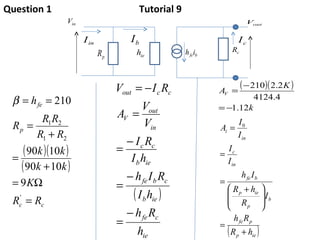
- 13. Question 9